EP1566864B1 - Steckdosenmodul für einen Stativkopf eines medizinischen Deckenstativs - Google Patents
Steckdosenmodul für einen Stativkopf eines medizinischen Deckenstativs Download PDFInfo
- Publication number
- EP1566864B1 EP1566864B1 EP05003591A EP05003591A EP1566864B1 EP 1566864 B1 EP1566864 B1 EP 1566864B1 EP 05003591 A EP05003591 A EP 05003591A EP 05003591 A EP05003591 A EP 05003591A EP 1566864 B1 EP1566864 B1 EP 1566864B1
- Authority
- EP
- European Patent Office
- Prior art keywords
- circuit board
- socket
- socket module
- electrical
- display device
- Prior art date
- Legal status (The legal status is an assumption and is not a legal conclusion. Google has not performed a legal analysis and makes no representation as to the accuracy of the status listed.)
- Expired - Lifetime
Links
- 125000006850 spacer group Chemical group 0.000 claims description 8
- 210000003128 head Anatomy 0.000 description 14
- 210000001331 nose Anatomy 0.000 description 6
- 238000009434 installation Methods 0.000 description 3
- QVGXLLKOCUKJST-UHFFFAOYSA-N atomic oxygen Chemical compound [O] QVGXLLKOCUKJST-UHFFFAOYSA-N 0.000 description 2
- 230000005611 electricity Effects 0.000 description 2
- 239000001301 oxygen Substances 0.000 description 2
- 229910052760 oxygen Inorganic materials 0.000 description 2
- 230000004308 accommodation Effects 0.000 description 1
- 239000003086 colorant Substances 0.000 description 1
- 239000004020 conductor Substances 0.000 description 1
- 230000008878 coupling Effects 0.000 description 1
- 238000010168 coupling process Methods 0.000 description 1
- 238000005859 coupling reaction Methods 0.000 description 1
- 230000001419 dependent effect Effects 0.000 description 1
- 230000037431 insertion Effects 0.000 description 1
- 238000003780 insertion Methods 0.000 description 1
- 238000004519 manufacturing process Methods 0.000 description 1
- 229940075473 medical gases Drugs 0.000 description 1
- 210000002345 respiratory system Anatomy 0.000 description 1
Images


Classifications
-
- H—ELECTRICITY
- H01—ELECTRIC ELEMENTS
- H01R—ELECTRICALLY-CONDUCTIVE CONNECTIONS; STRUCTURAL ASSOCIATIONS OF A PLURALITY OF MUTUALLY-INSULATED ELECTRICAL CONNECTING ELEMENTS; COUPLING DEVICES; CURRENT COLLECTORS
- H01R13/00—Details of coupling devices of the kinds covered by groups H01R12/70 or H01R24/00 - H01R33/00
- H01R13/66—Structural association with built-in electrical component
- H01R13/665—Structural association with built-in electrical component with built-in electronic circuit
- H01R13/6691—Structural association with built-in electrical component with built-in electronic circuit with built-in signalling means
-
- H—ELECTRICITY
- H01—ELECTRIC ELEMENTS
- H01R—ELECTRICALLY-CONDUCTIVE CONNECTIONS; STRUCTURAL ASSOCIATIONS OF A PLURALITY OF MUTUALLY-INSULATED ELECTRICAL CONNECTING ELEMENTS; COUPLING DEVICES; CURRENT COLLECTORS
- H01R13/00—Details of coupling devices of the kinds covered by groups H01R12/70 or H01R24/00 - H01R33/00
- H01R13/73—Means for mounting coupling parts to apparatus or structures, e.g. to a wall
- H01R13/74—Means for mounting coupling parts in openings of a panel
- H01R13/741—Means for mounting coupling parts in openings of a panel using snap fastening means
- H01R13/743—Means for mounting coupling parts in openings of a panel using snap fastening means integral with the housing
-
- H—ELECTRICITY
- H01—ELECTRIC ELEMENTS
- H01R—ELECTRICALLY-CONDUCTIVE CONNECTIONS; STRUCTURAL ASSOCIATIONS OF A PLURALITY OF MUTUALLY-INSULATED ELECTRICAL CONNECTING ELEMENTS; COUPLING DEVICES; CURRENT COLLECTORS
- H01R25/00—Coupling parts adapted for simultaneous co-operation with two or more identical counterparts, e.g. for distributing energy to two or more circuits
- H01R25/006—Coupling parts adapted for simultaneous co-operation with two or more identical counterparts, e.g. for distributing energy to two or more circuits the coupling part being secured to apparatus or structure, e.g. duplex wall receptacle
-
- H—ELECTRICITY
- H01—ELECTRIC ELEMENTS
- H01R—ELECTRICALLY-CONDUCTIVE CONNECTIONS; STRUCTURAL ASSOCIATIONS OF A PLURALITY OF MUTUALLY-INSULATED ELECTRICAL CONNECTING ELEMENTS; COUPLING DEVICES; CURRENT COLLECTORS
- H01R12/00—Structural associations of a plurality of mutually-insulated electrical connecting elements, specially adapted for printed circuits, e.g. printed circuit boards [PCB], flat or ribbon cables, or like generally planar structures, e.g. terminal strips, terminal blocks; Coupling devices specially adapted for printed circuits, flat or ribbon cables, or like generally planar structures; Terminals specially adapted for contact with, or insertion into, printed circuits, flat or ribbon cables, or like generally planar structures
- H01R12/70—Coupling devices
- H01R12/71—Coupling devices for rigid printing circuits or like structures
- H01R12/72—Coupling devices for rigid printing circuits or like structures coupling with the edge of the rigid printed circuits or like structures
- H01R12/722—Coupling devices for rigid printing circuits or like structures coupling with the edge of the rigid printed circuits or like structures coupling devices mounted on the edge of the printed circuits
- H01R12/728—Coupling devices without an insulating housing provided on the edge of the PCB
-
- H—ELECTRICITY
- H01—ELECTRIC ELEMENTS
- H01R—ELECTRICALLY-CONDUCTIVE CONNECTIONS; STRUCTURAL ASSOCIATIONS OF A PLURALITY OF MUTUALLY-INSULATED ELECTRICAL CONNECTING ELEMENTS; COUPLING DEVICES; CURRENT COLLECTORS
- H01R13/00—Details of coupling devices of the kinds covered by groups H01R12/70 or H01R24/00 - H01R33/00
- H01R13/648—Protective earth or shield arrangements on coupling devices, e.g. anti-static shielding
- H01R13/655—Protective earth or shield arrangements on coupling devices, e.g. anti-static shielding with earth brace
-
- H—ELECTRICITY
- H01—ELECTRIC ELEMENTS
- H01R—ELECTRICALLY-CONDUCTIVE CONNECTIONS; STRUCTURAL ASSOCIATIONS OF A PLURALITY OF MUTUALLY-INSULATED ELECTRICAL CONNECTING ELEMENTS; COUPLING DEVICES; CURRENT COLLECTORS
- H01R13/00—Details of coupling devices of the kinds covered by groups H01R12/70 or H01R24/00 - H01R33/00
- H01R13/66—Structural association with built-in electrical component
- H01R13/665—Structural association with built-in electrical component with built-in electronic circuit
- H01R13/6658—Structural association with built-in electrical component with built-in electronic circuit on printed circuit board
-
- H—ELECTRICITY
- H01—ELECTRIC ELEMENTS
- H01R—ELECTRICALLY-CONDUCTIVE CONNECTIONS; STRUCTURAL ASSOCIATIONS OF A PLURALITY OF MUTUALLY-INSULATED ELECTRICAL CONNECTING ELEMENTS; COUPLING DEVICES; CURRENT COLLECTORS
- H01R2103/00—Two poles
-
- H—ELECTRICITY
- H01—ELECTRIC ELEMENTS
- H01R—ELECTRICALLY-CONDUCTIVE CONNECTIONS; STRUCTURAL ASSOCIATIONS OF A PLURALITY OF MUTUALLY-INSULATED ELECTRICAL CONNECTING ELEMENTS; COUPLING DEVICES; CURRENT COLLECTORS
- H01R2201/00—Connectors or connections adapted for particular applications
- H01R2201/12—Connectors or connections adapted for particular applications for medicine and surgery
-
- H—ELECTRICITY
- H01—ELECTRIC ELEMENTS
- H01R—ELECTRICALLY-CONDUCTIVE CONNECTIONS; STRUCTURAL ASSOCIATIONS OF A PLURALITY OF MUTUALLY-INSULATED ELECTRICAL CONNECTING ELEMENTS; COUPLING DEVICES; CURRENT COLLECTORS
- H01R24/00—Two-part coupling devices, or either of their cooperating parts, characterised by their overall structure
- H01R24/76—Two-part coupling devices, or either of their cooperating parts, characterised by their overall structure with sockets, clips or analogous contacts and secured to apparatus or structure, e.g. to a wall
- H01R24/78—Two-part coupling devices, or either of their cooperating parts, characterised by their overall structure with sockets, clips or analogous contacts and secured to apparatus or structure, e.g. to a wall with additional earth or shield contacts
-
- H—ELECTRICITY
- H01—ELECTRIC ELEMENTS
- H01R—ELECTRICALLY-CONDUCTIVE CONNECTIONS; STRUCTURAL ASSOCIATIONS OF A PLURALITY OF MUTUALLY-INSULATED ELECTRICAL CONNECTING ELEMENTS; COUPLING DEVICES; CURRENT COLLECTORS
- H01R25/00—Coupling parts adapted for simultaneous co-operation with two or more identical counterparts, e.g. for distributing energy to two or more circuits
- H01R25/16—Rails or bus-bars provided with a plurality of discrete connecting locations for counterparts
- H01R25/164—Connecting locations formed by flush mounted apparatus
Definitions
- the invention relates to a socket module for a tripod head of a medical ceiling stand.
- Medical ceiling stands are used to hold medical devices such as surveillance monitors, respiratory systems, syringes, pumps, etc.
- Medical ceiling stands are used, for example, in operating rooms or intensive care rooms of hospitals for the accommodation of the necessary for operations, intensive care or examination of a patient systems. They have at least one horizontal, pivotable arm, of which one end is rotatably mounted on the ceiling, and the other end is connected to a vertical and also rotatably mounted column on which a tripod head and a device carrier are provided. Due to the rotatable support of the arm and the column, the ceiling stand can be moved to any position.
- the entire supply lines for electricity, compressed air, oxygen and other medical gases, etc. are led from the ceiling through the arm and the column into the tripod head. Connections are provided in the tripod head, to which the devices placed on the device carrier can be directly connected. In this way, cables are prevented from being laid on the ground, and the risk of tripping over lying cables or lines can be eliminated.
- Such a tripod head usually has several connections for electricity, oxygen, etc.
- On a front panel are appropriate coupling or socket connections. Inside the tripod head are the electrical sockets, etc. connected to each other with the appropriate cables or lines. This connection must be carried out by hand and is therefore correspondingly expensive.
- only a limited space for contacting or for the line connections is present in the interior of the tripod head, so that only a limited number of sockets, voltage indicators, etc. can be installed.
- additional components for each socket such as fuses or voltage indicators necessary, which occupy the already anyway small space and their manual wiring is almost impossible.
- the printed circuit boards can be prefabricated and are therefore available when needed. As a result, the assembly time can be considerably shortened in contrast to manual contacting.
- the contact can save space through a circuit board, so that it is possible to accommodate more sockets, etc. than before on the same surface.
- the assembly is mainly simplified by the fact that the individual components such as the socket, the fuse, the signal display device, etc. simply plugged onto the circuit board and then optionally soldered.
- the provision of contact pins that protrude perpendicular to the circuit board surface simplifies the attachment and contacting of the individual components substantially.
- a further advantageous embodiment of the invention is to prepare directly connections on the circuit board by plug, which are applied to the circuit board, so that the individual components are easily attached via the connector on the circuit board.
- Terminals for feeding or passage of electrical energy are particularly vorteil.haft, since no single contacting each individual component is more necessary. Only one terminal at the end of a circuit board must still be connected to the corresponding supply line.
- An advantageous embodiment of the signal display device by providing an LED or other light source on the circuit board and a lens element on the front panel allows the cost-effective realization of a signal display, such as a voltage display.
- a signal display such as a voltage display.
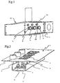
- Fig. 1 shows a tripod head 12, wherein only a socket module according to an embodiment of the present invention is shown on the right half.
- the left half in Fig. 1 may be provided with a corresponding socket module.
- the tripod head 12 has on its front side a front plate 19, which is divided into two in the present embodiment. Alternatively, a single continuous front panel is conceivable. In the front panel 19 a plurality of recesses are provided which serve to receive sockets 3, fuses 7 and for fixing potential equalization 21. In the present embodiment, three sockets 3 are provided, plus the associated equipotential bonding 21, two fuses 7 and a lens 5 for a later explained voltage display. 4
- the sockets 3 are arranged side by side in a horizontal orientation. But it is also any other, the space of the front panel 19 optimally exploiting arrangement conceivable.
- everyone Outlet 3 is associated with a pair of fuses 7, a lens 5 and a potential equalization 21. Depending on the size of the tripod head 12 and more or less sockets can be provided.
- FIG. 3 the back of the front panel 19 can be seen.
- Spacer bolts 15 are screwed to the front plate 19.
- the spacer bolts 15 are connected to spacers 14.
- In between latching plates 13 are inserted and bolted to the standoffs.
- the spacer bolts 14 are screwed to a printed circuit board 2.
- the sockets 3 have latching lugs 21, which are provided several times, wherein alternately a latching nose from the top in Fig. 5 or 6 extending downwardly wider, and a latching nose 21 from below in FIG 5 or 6 becomes wider towards the top.
- the distance between the oppositely arranged latching noses in auffactaufender direction is dimensioned so that it corresponds approximately to the thickness of a Einrastbleches 13.
- the latching noses 21 are arranged offset from each other by approximately the width of a latching nose. As shown in FIGS. 5 and 6, so the locking plates 13 are clamped between the latching noses 21. In this way, the sockets 3 can easily snap into the latching plates 13 and are thus fixed in position. In principle, however, other Befest Trentsmöglischkeiten for sockets are conceivable.
- the printed circuit board 2 has printed conductor tracks 22. These tracks 22 correspond to the necessary wiring of each outlet 3 or any other component that previously had to be manually wired electrically.
- Terminals 9 are provided on each printed circuit board at one end or at both ends, which are connected to the lines which are guided by the ceiling stand in the tripod head (not shown). By a single connection of a line in one of the terminals 9 thus, for example, a power supply for all sockets can be made simultaneously.
- 2 pins 23 are soldered in each circuit board. The contact pins 23 are perpendicular from the circuit board 2 in the direction of the sockets 3 and the other components. They are placed so that the sockets simply plugged onto the contact pins 23 and contacted, alternatively screwed, can be. It is thus no manual contacting of the individual outlets more necessary. The same applies to the other components.
- a terminal 18 which serves to make a contact with the equipotential 21.
- each outlet 3 is assigned two fuses 7.
- a fuse holder 6 is soldered to the circuit board 2.
- recesses are provided, through which the fuse holder 6 protrude.
- each fuse holder 6 can the desired fuse 7 are used. Since no direct manual contacting of the individual components is necessary, each fuse can be located very close to the socket. In the present embodiment, the two fuses are located immediately to the left of the socket 3.
- the voltage indicator has a light emitting diode 4 which is soldered on the printed circuit board 2. By using different LEDs different light colors are possible.
- a recess is provided, in which a lens element 5 is fixed, as shown in Fig. 2.
- LED 4 and the lens element 5 are between five and 10 millimeters distance. If the LED 4 lights up, the light is focused via the lens 5 and is clearly visible from all sides. Since the voltage display can thus be installed without manual contacting, hardly any space is required and the installation is simple and time-saving.
- the voltage display between the two fuses 7 is arranged immediately adjacent to the socket 3, so that the installation space required for this is minimal. This was not possible with the previous contact because there was not enough space available.
- each printed circuit board 2 is designed so that the contacting of all components is met with the necessary safety distances and cross sections.
- the connection of the sockets 3 takes place directly on the soldered contact pins 8, which lie in the grid of the socket outlets, as shown in Fig. 4 can be seen. Thus, no additional cables for contacting are required.
- a Abschottblech 16 is provided opposite to the front plate 19, on the other side of the circuit board 2.
- the Abschottblech 16 has a C-shaped cross-section, which encloses the entire arrangement of the socket module from the rear and serves as protection against contact or foreclosure.
- the Abschottblech 16 is bolted to the circuit board 2 by means of additional spacers 17.
Landscapes
- Engineering & Computer Science (AREA)
- Microelectronics & Electronic Packaging (AREA)
- Details Of Connecting Devices For Male And Female Coupling (AREA)
- Coupling Device And Connection With Printed Circuit (AREA)
- Apparatus For Radiation Diagnosis (AREA)
- Studio Devices (AREA)
- Accessories Of Cameras (AREA)
- Connecting Device With Holders (AREA)
Description
- Die Erfindung betrifft ein Steckdosenmodul für einen Stativkopf eines medizinischen Deckenstativs.
- Medizinische Deckenstative dienen zur hängenden Aufnahme von medizinischen Geräten wie beispielsweise Überwachungsmonitoren, Beatmungssystemen, Spritzen, Pumpen, etc.
- Medizinische Deckenstative werden beispielsweise in Operationssälen oder Intensivräumen von Krankenhäusern für die Unterbringung der für Operationen, die Intensivpflege bzw. Untersuchung eines Patienten notwendigen Systeme eingesetzt. Sie weisen mindestens einen horizontalen, schwenkbaren Arm auf, von dem ein Ende drehbar an der Decke befestigt ist, und das andere Ende mit einer vertikalen und ebenfalls drehbar gelagerten Säule verbunden ist, an der ein Stativkopf und ein Geräteträger vorgesehen sind. Durch die drehbare Lagerung des Arms und der Säule kann das Deckenstativ in jede beliebige Position gebracht werden.
- Die gesamten Versorgungsleitungen für Strom, Druckluft, Sauerstoff und andere medizinische Gase, etc. werden aus der Decke durch den Arm und die Säule in den Stativkopf geleitet. Im Stativkopf sind Anschlüsse vorgesehen, an die die auf dem Geräteträger plazierten Geräte direkt angeschlossen werden können. Auf diese Weise wird verhindert, daß Kabel am Boden verlegt werden müssen, und das Risiko, über am Boden liegende Kabel oder Leitungen zu stolpern, kann dadurch ausgeschaltet werden.
- Ein solcher Stativkopf weist meist mehrere Anschlüsse für Strom, Sauerstoff, etc. auf. An einer Frontplatte befinden sich entsprechende Kopplungs- bzw. Steckdosenanschlüsse. Im Inneren des Stativkopfs sind die Elektrosteckdosen, etc. mit den entsprechenden Kabeln oder Leitungen miteinander verbunden. Diese Verbindung muß von Hand durchgeführt werden und ist daher entsprechend aufwendig. Darüber hinaus ist im Inneren des Stativkopfs nur ein begrenzter Raum für die Kontaktierung bzw. für die Leitungsanschlüsse vorhanden, so daß nur eine begrenzte Anzahl von Steckdosen, Spannungsanzeigen, etc. eingebaut werden kann. Zudem sind je nach den gesetzlichen Vorschriften bei der Auslieferung in verschiedene Länder weitere Bauteile für jede Steckdose wie beispielsweise Sicherungen oder Spannungsanzeigen notwendig, die zusätzlich den ohnehin schon geringen Platz belegen und deren manuelles Verdrahten nahezu unmöglich ist.
- Dokument US-A-3263131 offenbart ein Steckdosenmodul mit einer Steckdose, die in einer Frontplatte vorgesehen ist.
- Es ist daher Aufgabe der vorliegenden Erfindung, ein Steckdosenmodul bereitzustellen, das einen einfachen Aufbau bei möglichst kleinem Bauraum ermöglicht, um möglichst viele Steckdosen, Sicherungen, Potentialausgleiche, etc. unterzubringen.
- Diese Aufgabe wird mit den Merkmalen des Anspruchs 1 gelöst. Weitere vorteilhafte Ausgestaltungen der Erfindung sind Gegenstand der Unteransprüche.
- Durch die erfindungsgemäße Lösung ist ein aufwendiges Verdrahten der einzelnen Bauelemente wie der Steckdosen, Sicherungen, etc. nicht mehr länger notwendig. Die Montage der einzelnen Bauelemente wird somit einfacher und schneller, was zu einer Kostenersparnis führt.
- Die Leiterplatten können vorgefertigt werden und stehen somit bei Bedarf zur Verfügung. Dadurch kann die Montagezeit im Gegensatz zur manuellen Kontaktierung erheblich verkürzt werden.
- Darüber hinaus kann die Kontaktierung durch eine Leiterplatte Raum sparen, so daß es möglich wird, mehr Steckdosen, etc. als bisher auf gleicher Fläche unterzubringen.
- Die Montage wird vor allem dadurch vereinfacht, daß die einzelnen Bauelemente wie die Steckdose, die Sicherung, die Signalanzeigevorrichtung, etc. einfach auf die Leiterplatte aufgesteckt und anschließend optional verlötet werden. Das Vorsehen von Kontaktstiften, die senkrecht zur Leiterplattenfläche vorstehen, vereinfacht das Befestigen und Kontaktieren der einzelnen Bauelemente wesentlich. Alternativ ist es möglich, die Steckdosen und übrigen Bauelemente mit Kontaktstiften zu versehen und auf der Leiterplatte Stecköffnungen vorzusehen, in die diese Kontaktstifte eingesteckt werden können. Eine weitere vorteilhafte Ausgestaltung der Erfindung liegt darin, direkt Anschlüsse auf der Leiterplatte durch Stecker vorzubereiten, die auf der Leiterplatte aufgebracht sind, so daß die einzelnen Bauelemente einfach über die Stecker auf der Leiterplatte befestigt werden.
- Anschlußklemmen zur Einspeisung oder Durchleitung von elektrischer Energie sind besonders vorteil.haft, da keine einzelne Kontaktierung jedes einzelnen Bauelementes mehr notwendig ist. Lediglich jeweils eine Anschlußklemme am Ende einer Leiterplatte muß noch mit der entsprechenden Versorgungsleitung verbunden werden.
- Das Montieren der Steckdose mittels in der Steckdose ausgebildeten Einrastnasen, die in den Zwischenraum zwischen zwei sich gegenüberliegenden Einrastnasen ein Einrastblech aufnehmen, vereinfacht die Montage erheblich. Dadurch werden auch Steckkräfte, die sonst auf die Verbindung zur Leiterplatte wirken, aufgenommen.
- Eine vorteilhafte Ausgestaltung der Signalanzeigevorrichtung durch Vorsehen einer LED oder eines anderen Leuchtmittels auf der Leiterplatte und eines Linsenelementes auf der Frontplatte ermöglicht die kostengünstige Realisierung einer Signalanzeige, wie beispielsweise einer Spannungsanzeige. Durch Auswahl eines geeigneten Linsenelementes in der Frontplatte ist keine allzu hohe Genauigkeit für die Anordnung beider Bauteile notwendig, was die Herstellung und Montage weiter vereinfacht.
- Weitere Merkmale und Zweckmäßigkeiten der Erfindung ergeben sich aus der Beschreibung eines bevorzugten Ausführungsbeispiels anhand der Figuren.
- Fig. 1
- ist eine perspektivische Gesamtdarstellung eines Stativkopfes.
- Fig. 2
- ist eine perspektivische Darstellung eines Steckdosenmoduls für einen Stativkopf schräg von oben.
- Fig. 3
- ist eine perspektivische Darstellung des Steckdosenmoduls aus Fig. 2 schräg von unten.
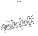
- Fig. 4
- ist eine perspektivische Darstellung einer Leiterplatte schräg von oben.
- Fig. 5
- ist eine schematische Darstellung einer Seitenansicht einer Steckdose und eines Einrastbleches.
- Fig. 6
- ist eine seitliche Darstellung einer Steckdose und eines Einrastbleches aus Fig. 5, jedoch um 90° gedreht.
- Fig. 1 zeigt einen Stativkopf 12, wobei nur auf der rechten Hälfte ein Steckdosenmodul gemäß einem Ausführungsbeispiel der vorliegenden Erfindung dargestellt ist. Selbstverständlich kann auch die linke Hälfte in Fig. 1 mit einem entsprechenden Steckdosenmodul versehen sein.
- Der Stativkopf 12 weist an seiner Vorderseite eine Frontplatte 19 auf, die im vorliegenden Ausführungsbeispiel zweigeteilt ist. Alternativ ist auch eine einzelne durchgehende Frontplatte denkbar. In der Frontplatte 19 sind mehrere Aussparungen vorgesehen, die zur Aufnahme von Steckdosen 3, Sicherungen 7 und zur Befestigung von Potentialausgleichen 21 dienen. Im vorliegenden Ausführungsbeispiel sind drei Steckdosen 3 vorgesehen, plus den zugehörigen Potentialausgleichen 21, je zwei Sicherungen 7 und einer Linse 5 für eine später erläuterte Spannungsanzeige 4.
- Die Steckdosen 3 sind nebeneinander in horizontaler Ausrichtung angeordnet. Es ist aber auch jede andere, den Platz der Frontplatte 19 optimal ausnutzende Anordnung denkbar. Jeder Steckdose 3 ist ein Paar Sicherungen 7, eine Linse 5 und ein Potentialausgleich 21 zugeordnet. Je nach Größe des Stativkopfes 12 können auch mehr oder weniger Steckdosen vorgesehen werden.
- In Fig. 3 ist die Rückseite der Frontplatte 19 zu sehen. Abstandsbolzen 15 sind mit der Frontplatte 19 verschraubt. Die Abstandsbolzen 15 sind mit Abstandsbolzen 14 verbunden. Dazwischen sind Einrastbleche 13 eingelegt und mit den Abstandsbolzen verschraubt. Die Abstandsbolzen 14 sind mit einer Leiterplatte 2 verschraubt. Durch geeignete Auswahl der Länge der Abstandsbolzen können die notwendigen Abstände zur Montage der Steckdosen 3 je nach Größe der Steckdosen und zur Verfügung stehender Einbautiefe des Stativkopfes 12 eingestellt werden, so daß beispielsweise die Steckdosen 3 mit der Frontplatte 19 bündig abschließen.
- Wie in den Fig. 5 und 6 gezeigt ist, weisen die Steckdosen 3 Einrastnasen 21 auf, die mehrfach vorgesehen sind, wobei abwechselnd eine Einrastnase von oben in Fig. 5 oder 6 nach unten verlaufend breiter wird, und eine Einrastnase 21 von unten in Fig. 5 oder 6 nach oben breiter werdend verläuft. Der Abstand zwischen den gegenüberliegend angeordneten Einrastnasen in aufeinanderzulaufender Richtung ist so bemessen, daß er in etwa der Blechstärke eines Einrastbleches 13 entspricht. Im vorliegenden Ausführungsbeispiel sind die Einrastnasen 21 etwa um die Breite einer Einrastnase versetzt zueinander angeordnet. Wie in den Fig. 5 und 6 gezeigt ist, werden so die Einrastbleche 13 zwischen den Einrastnasen 21 festgeklemmt. Auf diese Art und Weise können die Steckdosen 3 einfach in die Einrastbleche 13 einschnappen und werden somit in ihrer Position fixiert. Grundsätzlich sind aber auch andere Befestigungsmöglischkeiten für Steckdosen denkbar.
- Im folgenden wird die Leiterplatte 2 unter Bezugnahme auf Fig. 4 näher erläutert. Die Leiterplatte 2 weist gedruckte Leiterbahnen 22 auf. Diese Leiterbahnen 22 entsprechen den notwendigen Verdrahtungen jeder einzelnen Steckdose 3 oder jedes anderen Bauteils, das bislang manuell elektrisch verdrahtet werden mußte. Anschlußklemmen 9 sind auf jeder Leiterplatte an einem Ende oder an beiden Enden vorgesehen, die mit den Leitungen verbunden werden, die durch das Deckenstativ in den Stativkopf geführt werden (nicht dargestellt). Durch ein einziges Anklemmen einer Leitung in eine der Anschlußklemmen 9 kann somit beispielsweise eine Spannungsversorgung für alle Steckdosen gleichzeitig hergestellt werden. Ferner sind in jeder Leiterplatte 2 Kontaktstifte 23 eingelötet. Die Kontaktstifte 23 stehen senkrecht von der Leiterplatte 2 in Richtung der Steckdosen 3 und der übrigen Bauelemente vor. Sie sind so plaziert, daß die Steckdosen einfach auf die Kontaktstifte 23 aufgesteckt und kontaktiert, alternativ auch verschraubt, werden können. Es ist somit keine manuelle Kontaktierung der einzelnen Steckdosen mehr notwendig. Gleiches gilt auch für die übrigen Bauelemente.
- Des weiteren ist eine Klemme 18 vorgesehen, die dazu dient, eine Kontaktierung mit den Potentialausgleichen 21 zu verwirklichen.
- Im folgenden erfolgt eine Erläuterung der Befestigung der Sicherungen 7. Wie in den Fig. 1 und 2 zu sehen ist, sind im vorliegenden Ausführungsbeispiel jeder Steckdose 3 zwei Sicherungen 7 zugeordnet. Wie aus Fig. 4 hervorgeht, ist ein Sicherungshalter 6 auf der Leiterplatte 2 aufgelötet. In der Frontplatte 19 sind Aussparungen vorgesehen, durch die die Sicherungshalter 6 hindurchragen. In jedem Sicherungshalter 6 kann die gewünschte Sicherung 7 eingesetzt werden. Da keine direkte manuelle Kontaktierung der einzelnen Bauteile notwendig ist, kann jede Sicherung sehr nahe an der Steckdose angeordnet sein. Im vorliegenden Ausführungsbeispiel sind die beiden Sicherungen unmittelbar links von der Steckdose 3 angeordnet.
- Zwischen den beiden Sicherungen 7 ist jeweils eine Spannungsanzeige vorgesehen. Wie in den Fig. 2 und 4 gezeigt ist, weist die Spannungsanzeige eine Leuchtdiode 4 auf, die auf der Leiterplatte 2 angelötet ist. Durch den Einsatz verschiedener LEDs sind verschiedene Lichtfarben möglich. Auf der entsprechenden gegenüberliegenden Position auf der Frontplatte 19 ist eine Aussparung vorgesehen, in der ein Linsenelement 5 befestigt ist, wie in Fig. 2 gezeigt ist. Zwischen der auf der Leiterplatte 2 befestigten Leuchtdiode 4 und dem Linsenelement 5 sind zwischen fünf und 10 Millimeter Abstand. Leuchtet die Leuchtdiode 4 auf, wird das Licht über die Linse 5 gebündelt und ist von allen Seiten gut sichtbar. Da somit auch die Spannungsanzeige ohne manuelle Kontaktierung eingebaut werden kann, wird kaum Platz benötigt und die Montage ist einfach und zeitsparend. Wie in Fig. 1 gezeigt ist, ist die Spannungsanzeige zwischen beiden Sicherungen 7 unmittelbar neben der Steckdose 3 angeordnet, so daß der dazu benötigte Einbauraum minimal ist. Dies war mit der bisherigen Kontaktierung nicht möglich, da nicht genügend Einbauplatz vorhanden war.
- Das Layout jeder Leiterplatte 2 ist so gestaltet, daß die Kontaktierung aller Komponenten mit den notwendigen Sicherheitsabständen und Querschnitten erfüllt ist. Der Anschluß der Steckdosen 3 erfolgt direkt über die eingelöteten Kontaktstifte 8, die im Raster der Steckdosenanschlüsse liegen, wie in Fig. 4 zu sehen ist. Somit sind keine zusätzlichen Kabel zur Kontaktierung erforderlich.
- Wie des weiteren in Fig. 2 zu sehen ist, ist gegenüber der Frontplatte 19, auf der anderen Seite der Leiterplatte 2, ein Abschottblech 16 vorgesehen. Das Abschottblech 16 besitzt einen C-förmigen Querschnitt, der die gesamte Anordnung des Steckdosenmoduls von hinten umschließt und als Berührschutz bzw. Abschottung dient. Das Abschottblech 16 ist mit Hilfe weiterer Abstandsbolzen 17 an der Leiterplatte 2 verschraubt.
Claims (13)
- Steckdosenmodul (1) für einen Stativkopf (12) eines medizinischen Deckenstativs, mit mindestens einer Steckdose (3), die in einer Frontplatte (19) des Stativkopfs (12) vorgesehen ist, und mit einer Leiterplatte (2) mit für eine elektrische Verbindung der Steckdose (3) vorbereitetem aufgedruckten Leitungsbild und elektrischen Anschlüssen zur elektrischen Kontaktierung der Steckdose (3) durch Befestigen der Steckdose (3) auf den elektrischen Anschlüssen der Leiterplatte (2).
- Steckdosenmodul (1) nach Anspruch 1, mit mindestens einer Sicherung (7), die in der Frontplatte (19) vorgesehen ist, wobei die Leiterplatte (2) mit einem für eine elektrische Verbindung der Sicherung (7) vorbereiteten aufgedruckten Leitungsbild und elektrischen Anschlüssen zur elektrischen Kontaktierung der Sicherung (7) durch Befestigen der Sicherung (7) auf den elektrischen Anschlüssen der Leiterplatte (2) versehen ist.
- Steckdosenmodul (1) nach Anspruch 1 oder 2, mit mindestens einer Signalanzeigevorrichtung, die in der Frontplatte (19) vorgesehen ist, wobei die Leiterplatte (2) mit einem für eine elektrische Verbindung der Signalanzeigevorrichtung vorbereiteten aufgedruckten Leitungsbild und elektrischen Anschlüssen zur elektrischen Kontaktierung der Signalanzeigevorrichtung durch Befestigen der Signalanzeigevorrichtung auf den elektrischen Anschlüssen der Leiterplatte (2) versehen ist.
- Steckdosenmodul (1) nach dem vorhergehenden Anspruch, wobei die Signalanzeigevorrichtung eine Spannungsanzeige ist.
- Steckdosenmodul (1) nach einem der vorhergehenden Ansprüche, wobei die Anschlüsse auf der Leiterplatte (2) Kontaktstifte (8) aufweisen, die senkrecht zur Leiterplattenfläche vorstehen.
- Steckdosenmodul (1) nach einem der vorhergehenden Ansprüche 1 bis 3, wobei die Anschlüsse auf der Leiterplatte (2) Stecköffnungen zur Aufnahme von Kontaktstiften (8) aufweisen.
- Steckdosenmodul (1) nach einem der vorhergehenden Ansprüche 1 bis 3, wobei die Anschlüsse auf der Leiterplatte (2) Stecker aufweisen.
- Steckdosenmodul (1) nach einem der vorhergehenden Ansprüche, wobei die Leiterplatte (2) Anschlußklemmen (9) zur Einspeisung oder Durchleitung elektrischer Energie aufweist.
- Steckdosenmodul (1) nach einem der vorhergehenden Ansprüche 2 bis 8, wobei Sicherungshalter (6) für die Sicherungen (7) direkt auf der Leiterplatte (2) aufgelötet sind.
- Steckdosenmodul (1) nach einem der vorhergehenden Ansprüche 3 bis 9, wobei die Signalanzeigevorrichtung direkt auf der Leiterplatte (2) aufgelötet ist.
- Steckdosenmodul (1) nach einem der vorhergehenden Ansprüche, wobei die Steckdose (3) Einrastnasen aufweist, die mit einem Einrastblech (13), das über Abstandsbolzen (14, 15, 17) mit der Leiterplatte (2) verbindbar ist, verrastet.
- Steckdosenmodul (1) nach dem vorhergehenden Anspruch, wobei das Einrastblech (13) über eine Verlängerung der Abstandsbolzen (14, 15, 17) mit der Frontplatte (19) verbindbar ist.
- Steckdosenmodul (1) nach einem der vorhergehenden Ansprüche 3 bis 12, wobei die Signalanzeigevorrichtung eine LED (4) aufweist, die auf der Leiterplatte (2) befestigt ist, sowie ein Linsenelement, das in einer der LED (4) gegenüber vorgesehenen Bohrung in der Frontplatte (19) befestigt ist.
Applications Claiming Priority (2)
| Application Number | Priority Date | Filing Date | Title |
|---|---|---|---|
| DE102004008833 | 2004-02-20 | ||
| DE102004008833A DE102004008833A1 (de) | 2004-02-20 | 2004-02-20 | Steckdosenmodul für einen Stativkopf eines medizinischen Deckenstativs |
Publications (2)
| Publication Number | Publication Date |
|---|---|
| EP1566864A1 EP1566864A1 (de) | 2005-08-24 |
| EP1566864B1 true EP1566864B1 (de) | 2006-06-21 |
Family
ID=34706900
Family Applications (1)
| Application Number | Title | Priority Date | Filing Date |
|---|---|---|---|
| EP05003591A Expired - Lifetime EP1566864B1 (de) | 2004-02-20 | 2005-02-18 | Steckdosenmodul für einen Stativkopf eines medizinischen Deckenstativs |
Country Status (3)
| Country | Link |
|---|---|
| EP (1) | EP1566864B1 (de) |
| AT (1) | ATE331324T1 (de) |
| DE (2) | DE102004008833A1 (de) |
Families Citing this family (4)
| Publication number | Priority date | Publication date | Assignee | Title |
|---|---|---|---|---|
| JP5850523B2 (ja) | 2011-09-22 | 2016-02-03 | シチズン電子株式会社 | Ledチップ |
| EP3648257A1 (de) * | 2018-10-29 | 2020-05-06 | Werner Wirth GmbH | Steckverbinder, insbesondere für ein elektrofahrrad |
| PL3758157T3 (pl) | 2019-06-27 | 2025-03-17 | Erbe Elektromedizin Gmbh | Urządzenie z interfejsem serwisowym i sposób konserwacji urządzenia |
| CN110459908B (zh) * | 2019-07-24 | 2020-12-11 | 上海星杰装饰有限公司 | 一种等电位安装结构 |
Family Cites Families (14)
| Publication number | Priority date | Publication date | Assignee | Title |
|---|---|---|---|---|
| US3263131A (en) * | 1963-12-11 | 1966-07-26 | Gen Electric | Electric power busway with plug-in branch circuit takeoff |
| GB2097199A (en) * | 1981-04-21 | 1982-10-27 | Boardman Paul | Electrical socket |
| DE9112520U1 (de) * | 1991-10-05 | 1992-12-10 | Krone GmbH, 14167 Berlin | Verteilereinrichtung der Fernmelde- und Datentechnik |
| US5214565A (en) * | 1992-01-31 | 1993-05-25 | Fujitsu Network Transmission Systems, Inc. | Fuse holder heat sink bracket |
| DE4217512C1 (de) * | 1992-05-27 | 1993-06-09 | Hella Kg Hueck & Co, 4780 Lippstadt, De | |
| DE4423236C1 (de) * | 1994-07-02 | 1995-10-12 | Bauknecht Hausgeraete | Elektrische Steckverbindung für Leiterplatten |
| DE29509854U1 (de) * | 1995-06-17 | 1995-08-17 | Festo AG & Co, 73734 Esslingen | Elektrische Steckverbindungseinrichtung |
| JP2999708B2 (ja) * | 1996-02-28 | 2000-01-17 | 株式会社ハーネス総合技術研究所 | 電気接続箱 |
| DE19706157C1 (de) * | 1997-02-17 | 1998-02-12 | Maerkische Ges Fuer Medizin Te | Deckenstativ-Anordnung zur Aufnahme von medizinischen Geräten, wie von Infusionspumpen o. dgl. |
| DE29706898U1 (de) * | 1997-04-16 | 1997-08-14 | Bürkert Werke GmbH & Co., 74653 Ingelfingen | Gerätesteckdose |
| DE19826453C2 (de) * | 1998-06-13 | 2000-08-24 | Wieland Electric Gmbh | Durchführungsadapter für Schaltschränke |
| GB2353904A (en) * | 1999-09-02 | 2001-03-07 | Alberice Meters Ltd | Mains supply socket attached to a printed circuit board (PCB) |
| US6250956B1 (en) * | 1999-11-09 | 2001-06-26 | Pulizzi Engineering Inc. | Electrical equipment and method of assembling same |
| TW452245U (en) * | 2000-07-20 | 2001-08-21 | Pan Internat Ind Corp | Adapting electronic card device |
-
2004
- 2004-02-20 DE DE102004008833A patent/DE102004008833A1/de not_active Withdrawn
-
2005
- 2005-02-18 DE DE502005000025T patent/DE502005000025D1/de not_active Expired - Lifetime
- 2005-02-18 EP EP05003591A patent/EP1566864B1/de not_active Expired - Lifetime
- 2005-02-18 AT AT05003591T patent/ATE331324T1/de not_active IP Right Cessation
Also Published As
| Publication number | Publication date |
|---|---|
| DE502005000025D1 (de) | 2006-08-03 |
| EP1566864A1 (de) | 2005-08-24 |
| DE102004008833A1 (de) | 2005-09-08 |
| ATE331324T1 (de) | 2006-07-15 |
Similar Documents
| Publication | Publication Date | Title |
|---|---|---|
| DE69211833T2 (de) | Installationseinrichtung für Netzanschluss | |
| DE69938321T2 (de) | Elektrischer Koppler zur lösbaren Verbindung zwischen Haupteinheit und externer Einheit | |
| DE102004031707B4 (de) | Intelligenter Anschlusskasten für Kraftfahrzeuge | |
| EP2220965A2 (de) | Präsentationssystem mit Trägerprofilschiene | |
| DE4437316C2 (de) | Dezentrale Ein/Ausgabebaugruppe für elektronische Steuerungen | |
| AT14657U1 (de) | Leuchte mit auswechselbaren Leuchtmodulen | |
| AT515246A2 (de) | Profilleuchtensystem und Montageverfahren dafür | |
| DE102017111245A1 (de) | Stromverteiler | |
| EP2091113B1 (de) | Verbindungssystem für Lichtbänder oder Leuchten | |
| EP1273809B1 (de) | Klemmvorrichtung zum Befestigen von Platten, insbesondere Glasscheiben, inklusive elektrischer Anschlüsse | |
| WO2012109683A1 (de) | Vorrichtung zum verbinden und kontaktieren zumindest einer led-einheit, sowie led-einheit und leuchtsystem | |
| EP1520330B1 (de) | Träger für modulgehäuse | |
| EP1566864B1 (de) | Steckdosenmodul für einen Stativkopf eines medizinischen Deckenstativs | |
| DE2251020B2 (de) | Anschlussvorrichtung | |
| DE102010054156B4 (de) | Terminalsystem zum Anbringen eines Endgerätes an einem Ständerwerk und zum elektrischen Koppeln des Endgerätes an ein Netzwerk oder eine Verarbeitungseinheit | |
| DE3001870C2 (de) | ||
| EP0316259A2 (de) | Anschlussleiste aus mehreren Teilleisten | |
| WO2012135878A1 (de) | Vorrichtung zum befestigen und kontaktieren eines leuchtmittels und/oder eines leuchtmoduls, sowie leuchte | |
| DE2829721C3 (de) | Mosaikbaustein für Schalt- und Meldewarten | |
| DE19610037C2 (de) | Baugruppenträger | |
| DE9003879U1 (de) | Kabelstecker-Verteiler-Kasten | |
| DE102005032409B4 (de) | Modulgehäuse mit Durchgangsverdrahtung | |
| DE4242320C1 (de) | Vielpolige Steckverbindung aus einem Stecker und mindestens einem Gegenstecker für Leiterplatten | |
| DE19700057C2 (de) | Datenschiene für den Europäischen Installationsbus (EIB) | |
| EP2942838B1 (de) | Verbinder und damit gebildete leiterplattenanordnung |
Legal Events
| Date | Code | Title | Description |
|---|---|---|---|
| PUAI | Public reference made under article 153(3) epc to a published international application that has entered the european phase |
Free format text: ORIGINAL CODE: 0009012 |
|
| AK | Designated contracting states |
Kind code of ref document: A1 Designated state(s): AT BE BG CH CY CZ DE DK EE ES FI FR GB GR HU IE IS IT LI LT LU MC NL PL PT RO SE SI SK TR |
|
| AX | Request for extension of the european patent |
Extension state: AL BA HR LV MK YU |
|
| GRAP | Despatch of communication of intention to grant a patent |
Free format text: ORIGINAL CODE: EPIDOSNIGR1 |
|
| 17P | Request for examination filed |
Effective date: 20050825 |
|
| GRAS | Grant fee paid |
Free format text: ORIGINAL CODE: EPIDOSNIGR3 |
|
| AKX | Designation fees paid |
Designated state(s): AT BE BG CH CY CZ DE DK EE ES FI FR GB GR HU IE IS IT LI LT LU MC NL PL PT RO SE SI SK TR |
|
| GRAA | (expected) grant |
Free format text: ORIGINAL CODE: 0009210 |
|
| AK | Designated contracting states |
Kind code of ref document: B1 Designated state(s): AT BE BG CH CY CZ DE DK EE ES FI FR GB GR HU IE IS IT LI LT LU MC NL PL PT RO SE SI SK TR |
|
| PG25 | Lapsed in a contracting state [announced via postgrant information from national office to epo] |
Ref country code: SK Free format text: LAPSE BECAUSE OF FAILURE TO SUBMIT A TRANSLATION OF THE DESCRIPTION OR TO PAY THE FEE WITHIN THE PRESCRIBED TIME-LIMIT Effective date: 20060621 Ref country code: NL Free format text: LAPSE BECAUSE OF FAILURE TO SUBMIT A TRANSLATION OF THE DESCRIPTION OR TO PAY THE FEE WITHIN THE PRESCRIBED TIME-LIMIT Effective date: 20060621 Ref country code: LT Free format text: LAPSE BECAUSE OF FAILURE TO SUBMIT A TRANSLATION OF THE DESCRIPTION OR TO PAY THE FEE WITHIN THE PRESCRIBED TIME-LIMIT Effective date: 20060621 Ref country code: IT Free format text: LAPSE BECAUSE OF FAILURE TO SUBMIT A TRANSLATION OF THE DESCRIPTION OR TO PAY THE FEE WITHIN THE PRESCRIBED TIME-LIMIT;WARNING: LAPSES OF ITALIAN PATENTS WITH EFFECTIVE DATE BEFORE 2007 MAY HAVE OCCURRED AT ANY TIME BEFORE 2007. THE CORRECT EFFECTIVE DATE MAY BE DIFFERENT FROM THE ONE RECORDED. Effective date: 20060621 Ref country code: RO Free format text: LAPSE BECAUSE OF FAILURE TO SUBMIT A TRANSLATION OF THE DESCRIPTION OR TO PAY THE FEE WITHIN THE PRESCRIBED TIME-LIMIT Effective date: 20060621 Ref country code: PL Free format text: LAPSE BECAUSE OF FAILURE TO SUBMIT A TRANSLATION OF THE DESCRIPTION OR TO PAY THE FEE WITHIN THE PRESCRIBED TIME-LIMIT Effective date: 20060621 Ref country code: CZ Free format text: LAPSE BECAUSE OF FAILURE TO SUBMIT A TRANSLATION OF THE DESCRIPTION OR TO PAY THE FEE WITHIN THE PRESCRIBED TIME-LIMIT Effective date: 20060621 Ref country code: FI Free format text: LAPSE BECAUSE OF FAILURE TO SUBMIT A TRANSLATION OF THE DESCRIPTION OR TO PAY THE FEE WITHIN THE PRESCRIBED TIME-LIMIT Effective date: 20060621 Ref country code: SI Free format text: LAPSE BECAUSE OF FAILURE TO SUBMIT A TRANSLATION OF THE DESCRIPTION OR TO PAY THE FEE WITHIN THE PRESCRIBED TIME-LIMIT Effective date: 20060621 Ref country code: GB Free format text: LAPSE BECAUSE OF FAILURE TO SUBMIT A TRANSLATION OF THE DESCRIPTION OR TO PAY THE FEE WITHIN THE PRESCRIBED TIME-LIMIT Effective date: 20060621 Ref country code: IE Free format text: LAPSE BECAUSE OF FAILURE TO SUBMIT A TRANSLATION OF THE DESCRIPTION OR TO PAY THE FEE WITHIN THE PRESCRIBED TIME-LIMIT Effective date: 20060621 |
|
| REG | Reference to a national code |
Ref country code: GB Ref legal event code: FG4D Free format text: NOT ENGLISH |
|
| REG | Reference to a national code |
Ref country code: CH Ref legal event code: EP |
|
| REG | Reference to a national code |
Ref country code: IE Ref legal event code: FG4D Free format text: LANGUAGE OF EP DOCUMENT: GERMAN |
|
| REF | Corresponds to: |
Ref document number: 502005000025 Country of ref document: DE Date of ref document: 20060803 Kind code of ref document: P |
|
| PG25 | Lapsed in a contracting state [announced via postgrant information from national office to epo] |
Ref country code: DK Free format text: LAPSE BECAUSE OF FAILURE TO SUBMIT A TRANSLATION OF THE DESCRIPTION OR TO PAY THE FEE WITHIN THE PRESCRIBED TIME-LIMIT Effective date: 20060921 Ref country code: SE Free format text: LAPSE BECAUSE OF FAILURE TO SUBMIT A TRANSLATION OF THE DESCRIPTION OR TO PAY THE FEE WITHIN THE PRESCRIBED TIME-LIMIT Effective date: 20060921 |
|
| PG25 | Lapsed in a contracting state [announced via postgrant information from national office to epo] |
Ref country code: ES Free format text: LAPSE BECAUSE OF FAILURE TO SUBMIT A TRANSLATION OF THE DESCRIPTION OR TO PAY THE FEE WITHIN THE PRESCRIBED TIME-LIMIT Effective date: 20061002 |
|
| PG25 | Lapsed in a contracting state [announced via postgrant information from national office to epo] |
Ref country code: PT Free format text: LAPSE BECAUSE OF FAILURE TO SUBMIT A TRANSLATION OF THE DESCRIPTION OR TO PAY THE FEE WITHIN THE PRESCRIBED TIME-LIMIT Effective date: 20061121 |
|
| NLV1 | Nl: lapsed or annulled due to failure to fulfill the requirements of art. 29p and 29m of the patents act | ||
| ET | Fr: translation filed | ||
| GBV | Gb: ep patent (uk) treated as always having been void in accordance with gb section 77(7)/1977 [no translation filed] |
Effective date: 20060621 |
|
| REG | Reference to a national code |
Ref country code: IE Ref legal event code: FD4D |
|
| PG25 | Lapsed in a contracting state [announced via postgrant information from national office to epo] |
Ref country code: MC Free format text: LAPSE BECAUSE OF NON-PAYMENT OF DUE FEES Effective date: 20070228 |
|
| PLBE | No opposition filed within time limit |
Free format text: ORIGINAL CODE: 0009261 |
|
| STAA | Information on the status of an ep patent application or granted ep patent |
Free format text: STATUS: NO OPPOSITION FILED WITHIN TIME LIMIT |
|
| 26N | No opposition filed |
Effective date: 20070322 |
|
| BERE | Be: lapsed |
Owner name: TRUMPF KREUZER MEDIZIN SYSTEME G.M.B.H. + CO. KG Effective date: 20070228 |
|
| PG25 | Lapsed in a contracting state [announced via postgrant information from national office to epo] |
Ref country code: BE Free format text: LAPSE BECAUSE OF NON-PAYMENT OF DUE FEES Effective date: 20070228 |
|
| PG25 | Lapsed in a contracting state [announced via postgrant information from national office to epo] |
Ref country code: GR Free format text: LAPSE BECAUSE OF FAILURE TO SUBMIT A TRANSLATION OF THE DESCRIPTION OR TO PAY THE FEE WITHIN THE PRESCRIBED TIME-LIMIT Effective date: 20060922 |
|
| PG25 | Lapsed in a contracting state [announced via postgrant information from national office to epo] |
Ref country code: AT Free format text: LAPSE BECAUSE OF NON-PAYMENT OF DUE FEES Effective date: 20070218 Ref country code: BG Free format text: LAPSE BECAUSE OF FAILURE TO SUBMIT A TRANSLATION OF THE DESCRIPTION OR TO PAY THE FEE WITHIN THE PRESCRIBED TIME-LIMIT Effective date: 20060921 |
|
| PG25 | Lapsed in a contracting state [announced via postgrant information from national office to epo] |
Ref country code: EE Free format text: LAPSE BECAUSE OF FAILURE TO SUBMIT A TRANSLATION OF THE DESCRIPTION OR TO PAY THE FEE WITHIN THE PRESCRIBED TIME-LIMIT Effective date: 20060621 |
|
| PG25 | Lapsed in a contracting state [announced via postgrant information from national office to epo] |
Ref country code: IS Free format text: LAPSE BECAUSE OF NON-PAYMENT OF DUE FEES Effective date: 20070228 |
|
| PGRI | Patent reinstated in contracting state [announced from national office to epo] |
Ref country code: IT Effective date: 20090401 |
|
| PG25 | Lapsed in a contracting state [announced via postgrant information from national office to epo] |
Ref country code: CY Free format text: LAPSE BECAUSE OF FAILURE TO SUBMIT A TRANSLATION OF THE DESCRIPTION OR TO PAY THE FEE WITHIN THE PRESCRIBED TIME-LIMIT Effective date: 20060621 Ref country code: LU Free format text: LAPSE BECAUSE OF NON-PAYMENT OF DUE FEES Effective date: 20070218 |
|
| PG25 | Lapsed in a contracting state [announced via postgrant information from national office to epo] |
Ref country code: TR Free format text: LAPSE BECAUSE OF FAILURE TO SUBMIT A TRANSLATION OF THE DESCRIPTION OR TO PAY THE FEE WITHIN THE PRESCRIBED TIME-LIMIT Effective date: 20060621 Ref country code: HU Free format text: LAPSE BECAUSE OF FAILURE TO SUBMIT A TRANSLATION OF THE DESCRIPTION OR TO PAY THE FEE WITHIN THE PRESCRIBED TIME-LIMIT Effective date: 20061222 |
|
| REG | Reference to a national code |
Ref country code: CH Ref legal event code: PL |
|
| PG25 | Lapsed in a contracting state [announced via postgrant information from national office to epo] |
Ref country code: CH Free format text: LAPSE BECAUSE OF NON-PAYMENT OF DUE FEES Effective date: 20090228 Ref country code: LI Free format text: LAPSE BECAUSE OF NON-PAYMENT OF DUE FEES Effective date: 20090228 |
|
| REG | Reference to a national code |
Ref country code: FR Ref legal event code: PLFP Year of fee payment: 12 |
|
| PGFP | Annual fee paid to national office [announced via postgrant information from national office to epo] |
Ref country code: DE Payment date: 20160209 Year of fee payment: 12 Ref country code: IT Payment date: 20160222 Year of fee payment: 12 |
|
| PGFP | Annual fee paid to national office [announced via postgrant information from national office to epo] |
Ref country code: FR Payment date: 20160108 Year of fee payment: 12 |
|
| REG | Reference to a national code |
Ref country code: DE Ref legal event code: R119 Ref document number: 502005000025 Country of ref document: DE |
|
| REG | Reference to a national code |
Ref country code: FR Ref legal event code: ST Effective date: 20171031 |
|
| PG25 | Lapsed in a contracting state [announced via postgrant information from national office to epo] |
Ref country code: FR Free format text: LAPSE BECAUSE OF NON-PAYMENT OF DUE FEES Effective date: 20170228 Ref country code: DE Free format text: LAPSE BECAUSE OF NON-PAYMENT OF DUE FEES Effective date: 20170901 |
|
| PG25 | Lapsed in a contracting state [announced via postgrant information from national office to epo] |
Ref country code: IT Free format text: LAPSE BECAUSE OF FAILURE TO SUBMIT A TRANSLATION OF THE DESCRIPTION OR TO PAY THE FEE WITHIN THE PRESCRIBED TIME-LIMIT Effective date: 20170218 |