EP1566630A1 - Gasdetektor - Google Patents
Gasdetektor Download PDFInfo
- Publication number
- EP1566630A1 EP1566630A1 EP03774104A EP03774104A EP1566630A1 EP 1566630 A1 EP1566630 A1 EP 1566630A1 EP 03774104 A EP03774104 A EP 03774104A EP 03774104 A EP03774104 A EP 03774104A EP 1566630 A1 EP1566630 A1 EP 1566630A1
- Authority
- EP
- European Patent Office
- Prior art keywords
- temp
- exothermic
- gas
- detector
- temperature
- Prior art date
- Legal status (The legal status is an assumption and is not a legal conclusion. Google has not performed a legal analysis and makes no representation as to the accuracy of the status listed.)
- Withdrawn
Links
Images


Classifications
-
- G—PHYSICS
- G01—MEASURING; TESTING
- G01N—INVESTIGATING OR ANALYSING MATERIALS BY DETERMINING THEIR CHEMICAL OR PHYSICAL PROPERTIES
- G01N27/00—Investigating or analysing materials by the use of electric, electrochemical, or magnetic means
- G01N27/02—Investigating or analysing materials by the use of electric, electrochemical, or magnetic means by investigating impedance
- G01N27/04—Investigating or analysing materials by the use of electric, electrochemical, or magnetic means by investigating impedance by investigating resistance
- G01N27/14—Investigating or analysing materials by the use of electric, electrochemical, or magnetic means by investigating impedance by investigating resistance of an electrically-heated body in dependence upon change of temperature
- G01N27/18—Investigating or analysing materials by the use of electric, electrochemical, or magnetic means by investigating impedance by investigating resistance of an electrically-heated body in dependence upon change of temperature caused by changes in the thermal conductivity of a surrounding material to be tested
-
- G—PHYSICS
- G01—MEASURING; TESTING
- G01N—INVESTIGATING OR ANALYSING MATERIALS BY DETERMINING THEIR CHEMICAL OR PHYSICAL PROPERTIES
- G01N33/00—Investigating or analysing materials by specific methods not covered by groups G01N1/00 - G01N31/00
- G01N33/0004—Gaseous mixtures, e.g. polluted air
- G01N33/0009—General constructional details of gas analysers, e.g. portable test equipment
- G01N33/0027—General constructional details of gas analysers, e.g. portable test equipment concerning the detector
- G01N33/0036—General constructional details of gas analysers, e.g. portable test equipment concerning the detector specially adapted to detect a particular component
- G01N33/005—H2
-
- H—ELECTRICITY
- H01—ELECTRIC ELEMENTS
- H01M—PROCESSES OR MEANS, e.g. BATTERIES, FOR THE DIRECT CONVERSION OF CHEMICAL ENERGY INTO ELECTRICAL ENERGY
- H01M8/00—Fuel cells; Manufacture thereof
- H01M8/04—Auxiliary arrangements, e.g. for control of pressure or for circulation of fluids
- H01M8/04082—Arrangements for control of reactant parameters, e.g. pressure or concentration
- H01M8/04089—Arrangements for control of reactant parameters, e.g. pressure or concentration of gaseous reactants
-
- Y—GENERAL TAGGING OF NEW TECHNOLOGICAL DEVELOPMENTS; GENERAL TAGGING OF CROSS-SECTIONAL TECHNOLOGIES SPANNING OVER SEVERAL SECTIONS OF THE IPC; TECHNICAL SUBJECTS COVERED BY FORMER USPC CROSS-REFERENCE ART COLLECTIONS [XRACs] AND DIGESTS
- Y02—TECHNOLOGIES OR APPLICATIONS FOR MITIGATION OR ADAPTATION AGAINST CLIMATE CHANGE
- Y02E—REDUCTION OF GREENHOUSE GAS [GHG] EMISSIONS, RELATED TO ENERGY GENERATION, TRANSMISSION OR DISTRIBUTION
- Y02E60/00—Enabling technologies; Technologies with a potential or indirect contribution to GHG emissions mitigation
- Y02E60/30—Hydrogen technology
- Y02E60/50—Fuel cells
Definitions
- the present invention relates to a gas detector for detecting hydrogen leakage and humidity.
- Such fuel cell systems as discussed above are considered useful for application to home-use cogeneration systems as well as automobiles.
- the fuel cell systems are expected to grow more and more in the future as alternative sources of energy to replace the existing thermal power generation and gasoline engines that use fossil fuel. Because the fuel cells use hydrogen for the fuel, it is important that they are provided with safety measures. In other words, it is indispensable for the fuel cells to be equipped with hydrogen concentration detectors for detecting leakage of hydrogen to ensure the safety.
- hydrogen concentration detectors that detect hydrogen concentration by monitoring temperature change of heater elements based on the principle that a coefficient of thermal conductivity of hydrogen is extremely large as compared to other gases.
- the hydrogen concentration detector uses a temperature sensor element to electrically detect this temperature change.
- Platinum temperature-measuring elements are well known as the heater elements, and the temperature sensor elements used for such hydrogen concentration detectors. Since platinum has a relatively high specific resistance among metals, it generates heat in itself when an electric current is fed through. In addition, because platinum also has a relatively high temperature coefficient of resistance among metals, it can be used for detection of temperature change corresponding to the hydrogen concentration through a change in resistance.
- a gas detector contrived to use the above method is disclosed in the official publication of unexamined Japanese utility model, No. S62-12861.
- This gas detector uses two detectors of different heating temperatures, and a factor multiplier and an arithmetic unit to solve a set of simultaneous equations obtained from outputs of the two detectors.
- This gas detector can thus measure a level of concentration of the gas to be detected while eliminating influence of interfering gases.
- the above gas detector of the prior art shows a drawback when there is water vapor present as an interfering gas in the gas to be detected.
- a resistance of platinum changes precisely in proportion to the level of hydrogen concentration only if there is no water vapor.
- the water vapor if present, also changes the resistance of platinum.
- the gas detector is unable to determine what has caused the change in resistance, whether it is due to hydrogen, water vapor, or both of them in coexistence. It is for this reason to solve the above problem that the gas detector of the prior art makes arithmetic operation of the simultaneous equations to eliminate influence of the interfering gases.
- water vapor shows such characteristics that its coefficient of thermal conductivity rises with increase in absolute humidity, but start descending once the coefficient value reaches a peak level in an atmosphere in which the water vapor having polarities is mixed with unpolarized air, hydrogen and the like, although the coefficient value of water vapor is extremely smaller than that of hydrogen when present separately.
- a coefficient of thermal conductivity in the mixture of the water vapor and hydrogen rises once with increase in absolute humidity and descends after it reaches the peak level, as previously stated, when detecting hydrogen leakage. That is, the mixture shows a characteristic that the coefficient of thermal conductivity changes in a form of quadratic curve. Therefore, if a gas detector is adapted to use the prior art technique of solving the simultaneous equations as described above, it calculates only a level of hydrogen through arithmetic operation of the simultaneous equations in two unknowns, and has the following problems. That is, the operation is very complex as a signal processing technique of the sensor, and it gives rise to problems with regard to detecting accuracy, multiplicity of uses, cost of putting it to practical use, and so forth.
- a gas detector comprising: a high-temp exothermic detector unit having a high-temp exothermic gas sensor element and a high-temp exothermic temperature sensor element, each made of a resistor of which a resistance changes responsive to temperature, the high-temp exothermic gas sensor element exposed to a gas being detected, and the high-temp exothermic temperature sensor element sealed in an unperforated casing filled with dry air and maintained to generate heat to a temperature substantially equal to a self-heating temperature of the high-temp exothermic gas sensor element as measured in dry air; and a low-temp exothermic detector unit having a low-temp exothermic gas sensor element and a low-temp exothermic temperature sensor element, each made of a resistor of which a resistance changes responsive to temperature, the low-temp exothermic gas sensor element exposed to the gas being detected, and the low-temp exothermic temperature sensor element sealed in another unperforated casing filled with dry air and maintained to generate heat to a temperature substantially equal to a self-heating temperature of the
- the gas detector performs processes of: converting resistance values of the individual gas sensor elements that change responsive to hydrogen concentration, humidity and an ambient temperature, and resistance values of the individual temperature sensor elements that change responsive to the ambient temperature into electrical gas-level outputs corresponding to the hydrogen concentration and the humidity; normalizing the gas-level outputs gained from the individual detector units by using a hydrogen sensitivity conversion factor obtained under a known level of hydrogen concentration; obtaining a humidity-level output derived as a difference between the normalized outputs; and producing outputs representing levels of the hydrogen concentration and the humidity by correcting the normalized outputs with a humidity-level correction formula established through a correlation of a humidity-level correction value obtained from the humidity-level output gained under an environment of known humidity level and the individual normalized outputs responsive to the humidity.
- GDH high-temp exothermic gas sensor element
- a low-temp exothermic gas sensor element (hereinafter referred to as "GDL”) defines another gas sensor element that generates heat by itself to maintain it at a temperature lower than that of the GDH.
- a high-temp exothermic temperature sensor element defines a temperature sensor element that generates heat by itself to maintain it in a state of high temperature for the proper function as a sensor element.
- a low-temp exothermic temperature sensor element defines another temperature sensor element that generates heat by itself to maintain it at a temperature lower than that of the TDH. It is also desirable that these two temperatures differ by 10°C or greater, but a difference of about 50°C is more desirable. It is desirable in addition that the low temperature maintained by the GDL and TDL is 100°C or higher.
- a high-temp exothermic detector unit (referred to as "DPH") comprises the GDH and the TDH, and it additionally includes a circuit for operating them.
- a low-temp exothermic detector unit (referred to as "DPL") comprises the GDL and the TDL, and includes a circuit for operating them.
- Fig. 1A shows GDH 1a, TDH 1b, GDL 2a and TDL 2b.
- Each of these elements is composed of a thermistor, of which a structure is shown in Fig. 2.
- Heat generating resistors of any kind can be used as these elements, if resistances are variable responsive to temperature change.
- Thermistor element 4 used here is made of a sintered oxide compound composed of manganese, cobalt, copper and vanadium, which is cut into a disc-like shape of 1.2mm in diameter and 0.2mm in thickness. B-constant defining a temperature characteristic of it is 2,300K. However, any element having a value in a range of approximately 1,000 to 3,000K may also be used.
- Thermistor element 4 is provided with electrodes 5 formed on both surfaces thereof by printing and firing conductive paste of silver, palladium and platinum based material.
- Lead wires 6 made of a platinum wire of 0.15mm in diameter are connected electrically and mechanically to the both electrodes 5 with the conductive paste.
- Glass layer 7 of a low melting point is formed to cover the entire exterior surface of thermistor element 4, including the electrodes 5 and parts of lead wires 6.
- Glass layer 7 is formed by coating a pasty form glass powder having a firing temperature of 550°C mixed with organic solvent.
- Thermistor element 4 is concealed entirely in glass layer 7 to thus complete thermistor 8.
- Thermistors 8 produced in the manner as described above are prepared here for a total of four pieces.
- each thermistor 8 is made by resistance-welding lead wires 6 to pins 10 fixed to base 9, as shown in Fig. 3 (shown by marks "x" in the figure).
- the four pieces of assembled elements are used as GDH 1a, TDH 1b, GDL 2a and TDL 2b respectively.
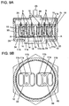
- Each of TDH 1b and TDL 2b is enclosed in unperforated casing 11b in a space filled with dry air, as shown in Fig. 1A and Fig. 1B.
- the unperforated casing 11b and base 9 are bonded and sealed by projection welding.
- the casing is formed of a metal. It is desirable to use stainless steel in the light of corrosion resistance and weldability.
- TDH 1b and TDL 2b constructed as above output voltages across their end terminals corresponding to their respective temperatures inside the gas detector without being influenced by the gas to be detected.
- Each of GDH 1a and GDL 2a is covered with perforated casing 11a having through holes of 1.2mm in diameter at four locations as shown in Fig. 1A.
- Perforated casing 11a and base 9 are bonded and sealed by projection welding.
- the temperature sensor elements (TDH 1b and TDL 2b) and the gas sensor elements (GDH 1a and GDL 2a) are made to be equal in their thermal capacity, so that both of these sensor elements have generally equal heat generating characteristic.
- the heat generating characteristic of TDH 1b becomes substantially equal to that of GDT 1a.
- the heat generating characteristic of TDL 2b also becomes substantially equal to that of GDL 2a. They can thus make an accurate temperature correction to the effect of ambient temperature.
- TDH 1b shows a temperature rise profile similar to that of GDH 1a during startup of the gas detector.
- TDL 2b also shows a temperature rise profile similar to that of GDL 2a.
- GDL 2a enclosed in perforated casing 11a and TDL 2b enclosed in unperforated casing 11b are connected together with heat conductive plate 33 made of a material of high coefficient of thermal conductivity such as copper, aluminum and the like material.
- GDH 1a enclosed in perforated casing 11a and TDH 1b enclosed in unperforated casing 11b are connected together with another heat conductive plate 33. Accordingly, the individual sensor elements are kept in a generally equal state of thermal conduction between perforated casings 11a and unperforated casings 11b provided around the sensor elements 1a, 1b, 2a and 2b and the surrounding environment.
- pins 10 are connected electrically and mechanically at their one ends to circuit board 15 by soldering. They are then housed in container 16 having a hexagonal exterior as shown in Fig. 1B.
- Flat heater 34 is placed in the vicinity of GDH 1a, TDH 1b, GDL 2a and TDL 2b as shown in Fig. 1A. Heater 34 is energized for about five seconds to a temperature of 200°C immediately after the startup of the detector.
- heater 34 heats up thermistors 8 to thereby lower their resistances to such values that make self-heating possible even when the ambient temperature is so low that the resistances of thermistor elements 4 are substantially large.
- the detector can be thus made operative even in a low temperature.
- heater 34 is shown as being operated during every startup, it may be operated only when the ambient temperature is low.
- microcomputer 32 may be used to monitor any of resistances and voltage values of thermistors 8, and heater 34 is operated only when the temperature is determined low, or the resistances are high. This can also save power consumption.
- Filter 18 made of a sintered metal is fitted in gas intake opening 17.
- Filter 18 has a circular shape, and it is disposed in a manner to project outward from container 16.
- the gas to be detected contains moisture, there is a possibility that dew condensation occurs inside container 16 depending on the condition of ambient temperature.
- the gas detector is therefore placed in such an orientation that gas intake opening 17 faces the direction of gravity, so as to let the condensed water flow out smoothly and drained to the outside of filter 18 by the gravity.
- Container cover 24 having conductor cable 23 disposed beforehand in a manner to pass through is placed above circuit board 15 inside container 16, and it is secured to container 16 by crimping. Furthermore, a space between circuit board 15 and container cover 24 is filled in its entirety with moisture resistant resin 25 injected through a filling opening (not shown in the figure) provided in container cover 24, and it is cured.
- the gas detector thus completed is fixed to a location where detection of gas concentration is desired, by tightening screw 26 formed on a peripheral portion of container 16.
- mounting hole 28 for the gas detector is formed in a part of pipe 27, as shown in Fig. 4.
- the gas detector is secured by tightening screw 26 into mounting hole 28.
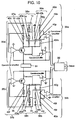
- GDH 1a, TDH 1b, GDL 2a and TDL 2b are connected in series with fixed resistors 29a, 29b, 29c and 29d respectively.
- fixed resistors 29a and 29b are of 220 ⁇ in resistance and fixed resistors 29c and 29d are of 500 ⁇ in resistance respectively. These resistors thus control the heating temperatures of GDH 1a and TDH 1b to approximately 190°C and those of GDL 2a and TDL 2b to approximately 140°C.
- D.C. power source 31 is connected to these circuits and supplies electrical power of 15V.
- two sensor elements 1a and 1b of DPH 35a, and two sensor elements 2a and 2b of DPL 35b are so controlled that their heating temperatures when measured in dry air are kept constant irrespective of an influence of the ambient temperature.
- the two sensor elements 1a and 1b of DPH 35a are controlled in a manner as described hereinafter to make their heating temperatures constant.
- Element resistance regulating circuit 36a in DPH 35a consists of fixed resistor 29e of 11k ⁇ and another fixed resistor 29f of 33k ⁇ connected in series. A voltage across the both ends of fixed resistor 29f serves as a control voltage.
- Ambient temperature detecting circuit 37a comprises fixed resistor 29b of 220 ⁇ connected in series to TDH 1b.
- a voltage across the both ends of fixed resistor 29b is a to-be-controlled voltage.
- a voltage applied to element resistance regulating circuit 36a, gas detecting circuit 38a comprising the series connection of GDH 1a and fixed resistor 29a of 220 ⁇ , reference voltage circuit 39a and ambient temperature detecting circuit 37a is regulated through an operational amplifier, a transistor and the like in response to changes in the ambient temperature, in a manner to equalize the to-be-controlled voltage with the control voltage.
- Element resistance regulating circuit 36b in DPL 35b comprises fixed resistor 29g of 43k ⁇ and another fixed resistor 29h of 100k ⁇ connected in series.
- a voltage across the both ends of fixed resistor 29h serves as a control voltage.
- Ambient temperature detecting circuit 37b comprises fixed resistor 29d of 500 ⁇ connected in series to TDL 2b.
- a voltage across the both ends of fixed resistor 29d is a to-be-controlled voltage.
- a voltage applied to element resistance regulating circuit 36b, gas detecting circuit 38b comprising the series connection of GDL 2a and fixed resistor 29c of 500 ⁇ , reference voltage circuit 39b and ambient temperature detecting circuit 37b is regulated through an operational amplifier, a transistor and the like in response to changes in the ambient temperature, in the manner as described above, to equalize the to-be-controlled voltage with the control voltage.
- TDL 2b and GDL 2a Since the resistances of TDL 2b and GDL 2a are kept to be constant at all the time as described, the heating temperatures of them can be controlled constant.
- the ambient temperatures of the individual sensor elements are kept generally uniform, they reduce changes in coefficient of thermal conductivity of the gas to be detected due to the effect of temperature.
- the gas detector can detect gas concentration with high accuracy.
- This embodiment also provides an advantage of shortening a warm-up time because it controls the self-heating temperatures of the individual sensor elements constant immediately after the startup of the gas detector.
- Reference voltage circuit 39a for producing a reference voltage comprises a series connection of fixed resistor 29i of a resistance value smaller than 11k ⁇ , fixed resistor 29j of 33k ⁇ and variable resistor 29k. A voltage across both ends of fixed resistor 29j is taken as the reference voltage.
- Gas detecting circuit 38a comprises fixed resistor 29a of 220 ⁇ connected in series to GDH 1a. A voltage across both ends of fixed resistor 29a is a gas-level output voltage, which is used in the signal processing to obtain a difference in voltage potential in comparison to the reference voltage. If there is a difference between the reference voltage and the gas-level output voltage in the air containing no hydrogen and humidity, a resistance of variable resistor 29k is adjusted to eliminate the difference.
- Reference voltage circuit 39b for producing another reference voltage comprises a series connection of fixed resistor 291 of a resistance value smaller than 43k ⁇ , fixed resistor 29m of 100k ⁇ , and variable resistor 29n. A voltage across both ends of fixed resistor 29m is used as the reference voltage.
- Gas detecting circuit 38b comprises fixed resistor 29c of 500 ⁇ connected in series to GDL 2a.
- a voltage across both ends of fixed resistor 29c is a gas-level output voltage, which is used in the signal processing to obtain a difference in voltage potential in comparison to the reference voltage. If there is a difference between the reference voltage and the gas-level output voltage, a resistance of variable resistor 29n is adjusted to eliminate the difference in the like manner as above.
- this embodiment can reduce variations in the potential differences between these reference voltages and gas-level output voltages attributable to the variations of the ambient temperature, and therefore it provides an advantage of making highly accurate detection.
- microcomputer 32 produces outputs corresponding to hydrogen concentration, humidity and temperature respectively by performing an operation which will be described later.
- the gas to be detected in the vicinity of the gas detector passes through filter 18 disposed to gas intake opening 17, and reaches GDH 1a, TDH 1b, GDL 2a and TDL 2b.
- GDH 1a and GDL 2a generate heat in themselves. If the gas being detected contains any of hydrogen and moisture, temperatures of GDH 1a and GDL 2a change because the hydrogen and moisture change the thermal conductivity of the gas being detected and amounts of the heat taken away from them depending on a level of the concentration.
- structures of TDH 1b and TDL 2b are such that they are individually sealed inside unperforated casings 11b with dry air.
- both TDH 1b and TDL 2b produce output voltages at both ends thereof that correspond to the temperatures inside the gas detector, without being influenced by the gas to be detected. These changes are converted into gas-level outputs respectively by the above method of signal processing, and input to microcomputer 32.
- thermistors 8 are used for sensor elements 1a, 1b, 2a and 2b, since they show a high level of sensitivity to hydrogen gas.
- thermistors 8 when used, are influenced considerably by the changes in the coefficient of thermal conductivity of hydrogen due to the ambient temperature. It is therefore necessary to make correction of the sensitivity to hydrogen concentration according to the ambient temperature. Since a hydrogen sensitivity conversion factor for each of the gas-level outputs is variable responsive to changes in the ambient temperature, the correction is made by using a sensitivity correction formula.
- the sensitivity correction formula is derived from a correlation between voltage outputs across the both ends of each of temperature sensor elements 1b and 2b and hydrogen sensitivity conversion factors under the environment of various ambient temperatures.
- gas-level outputs using a standard gas prepared by mixing 1% concentration of hydrogen in dry air, and voltages across the both ends of temperature sensor elements 1b and 2b are measured at temperatures of -40°C, 25°C and 80°C.
- the gas-level outputs in the standard gas generally have a tendency to decrease with increase in the temperature, as opposed to the voltages across the both ends of temperature sensor elements 1b and 2b, which can be considered of nearly a linear correlation.
- the voltages at both ends of the temperature sensor elements 1b and 2b are also input to microcomputer 32.
- Microcomputer 32 performs an arithmetic operation based on the individual gas-level outputs and the voltages at both ends of the temperature sensor elements 1b and 2b, and produces outputs corresponding to hydrogen concentration, humidity and temperature respectively.
- microcomputer 32 Description will be provided next of the operation performed by microcomputer 32. First, a correction data is established in the following manner when the gas detector is manufactured.
- Fig. 6A and Fig. 6B show a result of the measurement under a condition of 80°C in the ambient temperature.
- Fig. 6A shows the result of the measurement for DPH 35a on a coordinate plane of the hydrogen concentration in the axis of abscissas and the gas-level output in the axis of ordinates.
- the gas-level output increases in proportion to the hydrogen concentration, as shown in Fig. 6A.
- Fig. 6B shows the result of measurement of the gas-level output of DPL 35b.
- the gas-level output of DPL 35b also increases in proportion to the hydrogen concentration.
- the voltages across both ends of the individual temperature sensor elements 1b and 2b of DPH 35a and DPL 35b are not influenced by the state of the gas to be detected, and they both indicate the ambient temperature.
- the next step is to obtain relations between the voltage values across both ends of the temperature sensor elements 1b and 2b and the gas-level outputs of DPH 35a and DPL 35b respectively. Temperature correction data are then prepared from these data for the sensitivity versus hydrogen concentration.
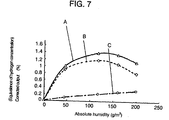
- measurement is taken of gas-level outputs from DPH 35a and DPL 35b while varying humidity in the air.
- Fig. 7 shows the result of measurement under the condition of 80°C in the ambient temperature.
- the axis of abscissas represents absolute humidity.
- the axis of ordinates represents the power output converted into hydrogen concentration.
- This graph exhibits computation of equivalent value to hydrogen concentration after conversion of the humidity-level output into hydrogen concentration.
- Curve “A” shows the gas-level output of DPH 35a corrected based on the idea of temperature correction for the sensitivity to hydrogen, as discussed with reference to Fig. 6A and 6B, that is, an error margin of the hydrogen detection accuracy (hereinafter referred to as "humidity offset”).
- curve “B” shows humidity offset obtained by correcting the gas-level output of DPL 35b.
- straight line “C” shows value obtained by subtracting the humidity offset of DPL 35b from the humidity offset of DPH 35a (referred to as difference "A” hereafter), representing humidity-level output.
- Microcomputer 32 performs the above operations to produce outputs corresponding to the hydrogen concentration and humidity, when it is input with the gas-level output of DPH 35a, the gas-level output of DPL 35b, and the voltages across both ends of temperature sensor elements 1b and 2b obtained when the gas detector is in operation. Referring to Fig. 8A and Fig. 8B, description is provided of an example of outputs when the above gas detector is actually operated.
- air samples having absolute humidity of approximately 120 g/m 3 were prepared by mixing them with hydrogen gases to various levels of concentration under the ambient temperature of 80°C, and they were switched one after another in the order of 0%, 0.4%, 0.8%, 1.6%, 0.8%, 0.4%, and 0%.
- Outputs of the gas detector were then measured after the operation of microcomputer 32.
- Fig. 8A shows a result of the hydrogen concentration outputs.
- the axis of abscissas indicates elapsed time during the measurements (in seconds), in which the hydrogen concentration levels were switched in the intervals of 900, 300, 300, 480, 480, 480, 480 seconds.
- the axis of ordinates indicates calculated value of the hydrogen concentration (%) derived from the gas-level output of DPH 35a, the gas-level output of DPL 35b and the voltages across both ends of temperature sensor elements 1b and 2b, by using the above calculation method. Because the curve in this graph representing the hydrogen concentration shows good response to the changes of the gases, it can be verified that the accuracy is also excellent.
- Fig. 8B shows a result of the humidity-level outputs.
- the axis of abscissas indicates the elapsed time during the measurements (in seconds), and the hydrogen concentration levels were switched in the same intervals as the above measurement of the hydrogen concentration.
- the axis of ordinates indicates output of absolute humidity-level corresponding to the hydrogen concentration.
- the humidity-level output shows no variation in Fig. 8 B, although the hydrogen concentration level has changed substantially during the measurement, as shown in Fig. 8A. In other words, it is clear that the gas detector accurately outputs only the absolute humidity without being influenced by the changes in the hydrogen concentration.
- this level of the absolute humidity agrees with a reading taken on the gas being measured by humidity measuring instrument in the close vicinity of the gas detector. It is obvious from the above results that the gas detector of the first exemplary embodiment can detect both of the hydrogen concentration and humidity independently with high accuracy.
- the gas detector according to the first exemplary embodiment can be used to compose an apparatus for controlling a fuel cell system and an automobile equipped with it so as to safely shut off hydrogen even if leakage occurs from the system.
- a gas detector of this exemplary embodiment differs from that of the first exemplary embodiment in respects that DPH 35a comprises second TDH 1c, and DPL 35b comprises second TDL 2c, in addition to the structure of the first exemplary embodiment.
- second TDH 1c and second TDL 2c are each composed of a thermistor, like those of the first exemplary embodiment.
- Fig. 2 shows a structure.
- second TDH 1c and second TDL 2c are analogous to the like elements described in the first exemplary embodiment.
- each of the sensor elements is enclosed in unperforated casing 11b in a space filled with dry air, and the unperforated casing 11b and base 9 are bonded and sealed by projection welding.
- Second TDH 1c and second TDL 2c thus output voltages across their end terminals according to their respective temperatures inside the gas detector without being influenced by the gas to be detected. Accordingly, the gas detector provides an advantage of detecting gas concentration highly accurately in a wide range of temperatures by adopting the above structure in which combinations of the two temperature sensor elements 1b and 2b, and 1c and 2c are placed inside their respective detector units 35a and 35b.
- GDH 1a, second TDH 1c and fixed resistor 40a of 220 ⁇ are connected in series to form gas detecting circuit 38a.
- Fixed resistor 40b of 75 ⁇ and fixed resistor 40c of 220 ⁇ are connected to each end of TDH 1b in series thereto, to form ambient temperature detecting circuit 37a.
- GDL 2a, second TDL 2c and fixed resistor 40d of 500 ⁇ are connected in series to form gas detecting circuit 38b.
- Fixed resistor 40e of 320 ⁇ and fixed resistor 40f of 500 ⁇ are connected to each end of TDH 2b in series thereto, to form another ambient temperature detecting circuit 37b.
- heating temperatures of GDH 1a, TDH 1b and second TDH 1c are controlled individually to become approximately 190°C.
- heating temperatures of GDL 2a, TDL 2b and second TDL 2c are controlled individually to become approximately 140°C.
- D.C. power source 31 is connected to these circuits and supplies electric power of 15V
- three sensor elements 1a, 1b and 1c of DPH 35a, and another set of three sensor elements 2a, 2b and 2c of DPL 35b are so controlled that their heating temperatures as measured in dry air are kept constant without being influenced by the ambient temperature.
- the three sensor elements 1a, 1b and 1c of DPH 35a are controlled in a manner as described hereinafter to make their heating temperatures constant.
- Element resistance regulating circuit 36a in DPH 35a consists of fixed resistor 40g of 293k ⁇ , fixed resistor 40h of 100k ⁇ and another fixed resistor 40i of 100k ⁇ connected in series. A voltage across the both ends of fixed resistor 40i serves as a control voltage.
- Ambient temperature detecting circuit 37a comprises fixed resistor 40b of 75 ⁇ and another fixed resistor 40c of 220 ⁇ connected in series with TDH 1b at each end thereof. A voltage across the both ends of fixed resistor 40b is a to-be-controlled voltage.
- a voltage applied to element resistance regulating circuit 36a, gas detecting circuit 38a comprising the series connection of GDH 1a, second TDH 1c and fixed resistor 41a of 220 ⁇ , reference voltage circuit 39a and ambient temperature detecting circuit 37a is regulated through an operational amplifier, a transistor and the like in response to changes in the ambient temperature, so as to equalize the to-be-controlled voltage with the control voltage. Since the resistances of GDH 1a, TDH 1b and second TDH 1c are kept to be constant at all the time as described above, the heating temperatures of them can be maintained constant.
- Element resistance regulating circuit 36b of DPL 35b comprises fixed resistor 40j of 156k ⁇ , fixed resistor 40k of 100k ⁇ and another fixed resistor 401 of 100k ⁇ connected in series. A voltage across the both ends of fixed resistor 401 serves as a control voltage.
- Ambient temperature detecting circuit 37b comprises fixed resistor 40e of 320 ⁇ and another fixed resistor 40f of 500 ⁇ connected in series to TDL 2b at each end thereof. A voltage across the both ends of fixed resistor 40e is a to-be-controlled voltage.
- a voltage applied to element resistance regulating circuit 36b, gas detecting circuit 38b comprising the series connection of GDL 2a, second TDL 2c and fixed resistor 40d of 500 ⁇ , reference voltage circuit 39b and ambient temperature detecting circuit 37b is regulated through an operational amplifier, a transistor and the like in response to changes in the ambient temperature, so as to equalize the to-be-controlled voltage with the control voltage.
- the resistances of GDL 2a, TDL 2b and second TDL 2c kept to be constant at all the time as described, the heating temperatures of them can be maintained constant. Since the ambient temperatures of the individual sensor elements are kept generally uniform, they reduce changes in coefficient of thermal conductivity of the gas to be detected due to the effect of temperature.
- this embodiment provides the gas detector with such advantages that it can detect gas concentration with high accuracy, and shorten a warm-up time because it controls the self- heating temperatures of the individual sensor elements to be constant immediately after the startup of the gas detector.
- Reference voltage circuit 39a for producing a reference voltage comprises a series connection of fixed resistor 40m of 293k ⁇ , fixed resistor 40n of a resistance value smaller than 100k ⁇ , fixed resistor 40o of 100k ⁇ , and variable resistor 40p. A voltage across both ends of fixed resistor 40o is taken as the reference voltage.
- Gas detecting circuit 38a comprises a series connection of GDH 1a, second TDH 1c and fixed resistor 40a of 220 ⁇ . A voltage across both ends of second TDH 1c is a gas-level output voltage. Signal processing is carried out to obtain a difference in voltage potential between the gas-level output voltage and the reference voltage. If there is a difference between the reference voltage and the gas-level output voltage in the air containing no hydrogen and humidity, a resistance of variable resistor 40p is adjusted to eliminate the difference.
- Reference voltage circuit 39b for producing another reference voltage comprises a series connection of fixed resistor 40q of 156k ⁇ , fixed resistor 40r of a resistance value smaller than 100k ⁇ , fixed resistor 40s of 100k ⁇ , and variable resistor 40t. A voltage across both ends of fixed resistor 40s is used as the reference voltage.
- Gas detecting circuit 38b comprises GDL 2a, second TDL 2c and fixed resistor 40d of 500 ⁇ connected in series. A voltage across both ends of second TDL 2c is a gas-level output voltage. Signal processing is carried out to obtain another difference in voltage potential between the gas-level output voltage and the reference voltage. If there is a difference between the reference voltage and the gas-level output voltage in the air containing no hydrogen and humidity, a resistance of variable resistor 40t is adjusted to eliminate the difference.
- heating characteristics of the individual gas sensor elements 1a and 2a, and another heating characteristics of the individual second temperature sensor elements 1c and 2c are made nearly equal in their ratios to a variety of temperatures.
- this embodiment can therefore reduce variations in the potential differences between these reference voltages and gas-level output voltages attributable to the variations of the ambient temperature, and it thus provides an advantage of making highly accurate detection.
- the gas-level outputs of DPH 35a and DPL 35b obtained through the above signal processing, and voltages appearing at both ends of the individual temperature sensor elements 1b, 1c, 2b and 2c are input to microcomputer 32.
- Microcomputer 32 produces outputs corresponding to hydrogen concentration, humidity and temperature respectively by performing an operation similar to that of the first exemplary embodiment.
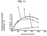
- Fig. 11 shows the result of evaluation of the humidity characteristic under the condition of 80°C in the ambient temperature.
- the axis of abscissas represents absolute humidity.
- Curve "A” shows the gas-level output of DPH 35a corrected based on the idea of temperature correction for the sensitivity to hydrogen, that is, an error margin of the hydrogen detection accuracy (referred to as "humidity offset").
- curve “B” shows humidity offset obtained by correcting the gas-level output of DPL 35b.
- straight line “C” shows value obtained by subtracting the humidity offset of DPL 35b from the humidity offset of DPH 35a (referred to as difference "B"), representing humidity-level output.
- the humidity-level output exhibited by the difference "B" is proportional to the absolute humidity, as shown in Fig. 11. Accordingly, since it is proportional to the absolute humidity like that of the first exemplary embodiment, it can be used as a humidity-level output. By obtaining this humidity-level output, it is possible to make correction of the humidity offset as well as calculation of the absolute humidity.
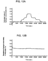
- Fig. 12A and Fig. 12B show an example of power outputs of the gas detector according to the second exemplary embodiment. A method of this experiment is identical to that of the first exemplary embodiment.
- Fig. 12A shows a result of the hydrogen concentration outputs.
- the axis of abscissas indicates elapsed time during the measurements (in seconds), in which the hydrogen concentration levels were switched in the intervals of 900, 300, 300, 480, 480, 480, 480 seconds.
- the axis of ordinates indicates calculated value of the hydrogen concentration (in %) derived from the gas-level output of DPH 35a, the gas-level output of DPL 35b and any of the voltages across both ends of temperature sensor elements 1b and 2b and the voltages across both ends of temperature sensor elements 1c and 2c, by using the above calculation method. Because the curve in this graph representing the hydrogen concentration shows good response to the changes of the gases, it can be verified that the accuracy is also excellent.
- Fig. 12B shows a result of the humidity-level outputs.
- the axis of abscissas indicates the elapsed time during the measurements (in seconds), and the hydrogen concentration levels were switched in the same intervals as the above measurement of the hydrogen concentration.
- the axis of ordinates indicates output of absolute humidity-level corresponding to the hydrogen concentration.
- the humidity-level output shows no variation, although the hydrogen concentration level has changed substantially during the measurement as shown in Fig. 12A. In other words, the gas detector can output only the absolute humidity level accurately without being influenced by the changes of the hydrogen concentration.
- this level of the absolute humidity agrees with a reading taken on the gas being measured by humidity measuring instrument in the close vicinity of the gas detector.
- This gas detector can provide a sufficiently high accuracy even when it is used for air conditioning control of a room space in an automobile and the like. According to the above results, it is apparent that the gas detector of the second exemplary embodiment can also detect both the hydrogen concentration and humidity independently with the same high accuracy as that of the first exemplary embodiment.
- a gas detector of this invention is adaptable for use in a system for detecting hydrogen leakage from an apparatus used in the normal atmosphere since it can detect hydrogen concentration and humidity independently with respect to each other.
Landscapes
- Chemical & Material Sciences (AREA)
- Life Sciences & Earth Sciences (AREA)
- Health & Medical Sciences (AREA)
- Engineering & Computer Science (AREA)
- Immunology (AREA)
- Physics & Mathematics (AREA)
- Analytical Chemistry (AREA)
- Biochemistry (AREA)
- General Health & Medical Sciences (AREA)
- General Physics & Mathematics (AREA)
- Electrochemistry (AREA)
- Pathology (AREA)
- Chemical Kinetics & Catalysis (AREA)
- Combustion & Propulsion (AREA)
- Food Science & Technology (AREA)
- Medicinal Chemistry (AREA)
- Manufacturing & Machinery (AREA)
- Sustainable Development (AREA)
- Sustainable Energy (AREA)
- General Chemical & Material Sciences (AREA)
- Investigating Or Analyzing Materials By The Use Of Electric Means (AREA)
- Air-Conditioning For Vehicles (AREA)
- Fuel Cell (AREA)
Applications Claiming Priority (3)
| Application Number | Priority Date | Filing Date | Title |
|---|---|---|---|
| JP2002337684 | 2002-11-21 | ||
| JP2002337684A JP4016813B2 (ja) | 2002-11-21 | 2002-11-21 | ガス検出器とそれを用いた燃料電池システムおよび自動車 |
| PCT/JP2003/014849 WO2004046706A1 (ja) | 2002-11-21 | 2003-11-20 | ガス検出器 |
Publications (2)
| Publication Number | Publication Date |
|---|---|
| EP1566630A1 true EP1566630A1 (de) | 2005-08-24 |
| EP1566630A4 EP1566630A4 (de) | 2012-03-07 |
Family
ID=32321851
Family Applications (1)
| Application Number | Title | Priority Date | Filing Date |
|---|---|---|---|
| EP03774104A Withdrawn EP1566630A4 (de) | 2002-11-21 | 2003-11-20 | Gasdetektor |
Country Status (4)
| Country | Link |
|---|---|
| US (1) | US7028530B2 (de) |
| EP (1) | EP1566630A4 (de) |
| JP (1) | JP4016813B2 (de) |
| WO (1) | WO2004046706A1 (de) |
Families Citing this family (21)
| Publication number | Priority date | Publication date | Assignee | Title |
|---|---|---|---|---|
| JP4045549B2 (ja) * | 2004-02-12 | 2008-02-13 | 株式会社デンソー | 水素濃度検出装置及び水素濃度検出方法 |
| JP4692026B2 (ja) * | 2005-03-08 | 2011-06-01 | パナソニック株式会社 | ガスセンサ |
| JP2006327396A (ja) | 2005-05-26 | 2006-12-07 | Honda Motor Co Ltd | 燃料電池自動車の水素センサ取り付け構造 |
| KR100980995B1 (ko) * | 2007-06-19 | 2010-09-07 | 현대자동차주식회사 | 연료전지용 지능형 전극막 |
| JP5839436B2 (ja) | 2010-12-02 | 2016-01-06 | ナブテスコ株式会社 | 光学センサ |
| EP2647979A4 (de) * | 2010-12-02 | 2017-01-25 | Nabtesco Corporation | Untersetzungsgetriebe für industrieroboter |
| JP5342602B2 (ja) * | 2011-05-20 | 2013-11-13 | 本田技研工業株式会社 | ガスセンサ |
| US8668997B2 (en) | 2011-06-20 | 2014-03-11 | United Technologies Corporation | System and method for sensing and mitigating hydrogen evolution within a flow battery system |
| US20140070827A1 (en) * | 2012-09-13 | 2014-03-13 | Alliance For Sustainable Energy, Llc | Systems and methods for compensated barrier permeability testing |
| DE102013014144B4 (de) * | 2013-08-23 | 2021-01-21 | Thermo Electron Led Gmbh | Wärmeleitfähigkeitsdetektor mit geschlossener Referenzkavität |
| EP2887057A1 (de) * | 2013-12-17 | 2015-06-24 | Sensirion AG | Vorrichtung und Verfahren der Luftfeuchte kompensierten Gaskonzentrationsüberwachung mittels thermischer Leifähigkeitsmessungen |
| US9835574B2 (en) * | 2014-07-02 | 2017-12-05 | Stmicroelectronics S.R.L. | Gas measurement device and measurement method thereof |
| EP3315956A1 (de) * | 2016-10-31 | 2018-05-02 | Sensirion AG | Multiparametrischer sensor mit brückenstruktur |
| CN109781716A (zh) * | 2017-11-13 | 2019-05-21 | 塔能股份公司 | 气体指示器 |
| CN109374671B (zh) * | 2018-08-31 | 2023-05-16 | 中国核电工程有限公司 | 一种高温氢气浓度测量元件 |
| CN111948338B (zh) * | 2019-05-15 | 2022-06-24 | 许俊杰 | 提高有害气体侦测器判断的方法 |
| US11162928B2 (en) * | 2019-11-04 | 2021-11-02 | Invensense, Inc. | Humidity correction method in thermistor based gas sensing platform |
| GB2604896A (en) * | 2021-03-17 | 2022-09-21 | Enapter S R L | Modular electrochemical system |
| JP2024066243A (ja) * | 2022-11-01 | 2024-05-15 | ローム株式会社 | 水素検出システム |
| JP2024067737A (ja) * | 2022-11-07 | 2024-05-17 | Tdk株式会社 | ガスセンサ |
| CN118549491B (zh) * | 2024-07-24 | 2024-11-29 | 沃尔特电子(苏州)有限公司 | 一种用于热导式气体探头浓度测量方法 |
Family Cites Families (19)
| Publication number | Priority date | Publication date | Assignee | Title |
|---|---|---|---|---|
| DE386908C (de) * | 1922-07-29 | 1923-12-19 | Siemens & Halske Akt Ges | Verfahren zur Messung des Kohlenoxydgehalts und Kohlendioxyd- (Kohlensaeure-) Gehalts von Rauchgasen vermittels gleicher Vorrichtungen |
| DE648669C (de) * | 1927-02-03 | 1937-08-09 | Hermann Heinicke | Vorrichtung zur selbsttaetigen Analyse von Mischgasen durch Messung auf elektrischem Wege |
| US2512857A (en) * | 1946-02-23 | 1950-06-27 | William G Gow | Gas cell |
| US3429178A (en) * | 1965-01-07 | 1969-02-25 | Enoch J Durbin | Measuring system |
| FR1494162A (fr) * | 1966-07-07 | 1967-09-08 | Charbonnages De France | Perfectionnements aux catharomètres |
| JPS56148047A (en) * | 1980-04-18 | 1981-11-17 | Koumiyou Rikagaku Kogyo Kk | Thermal conductivity type gas detector |
| US4399684A (en) * | 1981-11-27 | 1983-08-23 | Sierra Monitor Corporation | Gas measurement method |
| JPH0635985B2 (ja) | 1985-07-10 | 1994-05-11 | 株式会社明電舍 | 回転体の速度検出器 |
| US4928513A (en) * | 1986-07-29 | 1990-05-29 | Sharp Kabushiki Kaisha | Sensor |
| US4896143A (en) * | 1987-04-24 | 1990-01-23 | Quantum Group, Inc. | Gas concentration sensor with dose monitoring |
| JPH04291141A (ja) | 1991-03-20 | 1992-10-15 | Ngk Insulators Ltd | 可燃ガス検出装置およびその補正演算方法 |
| US5856780A (en) * | 1991-10-24 | 1999-01-05 | Capteur Sensors & Analysers, Ltd. | Semiconductor sensors and method for detecting fires using such sensors |
| US5297419A (en) * | 1992-07-16 | 1994-03-29 | Thermco Instrument Corporation | Linearizing gas analyzer |
| JP2889909B2 (ja) * | 1993-08-10 | 1999-05-10 | リコーエレメックス株式会社 | 雰囲気計 |
| US5551283A (en) * | 1993-08-10 | 1996-09-03 | Ricoh Seiki Company, Ltd. | Atmosphere measuring device and flow sensor |
| JP3343801B2 (ja) * | 1994-12-29 | 2002-11-11 | 光照 木村 | 湿度センサ |
| JP3385248B2 (ja) * | 1999-10-29 | 2003-03-10 | 光明理化学工業株式会社 | ガスセンサ |
| JP2001141682A (ja) | 1999-11-09 | 2001-05-25 | New Cosmos Electric Corp | 気体熱伝導式ガス検知装置及び低分子量ガス検知用補償素子 |
| KR100379471B1 (ko) * | 2000-07-19 | 2003-04-10 | 엘지전자 주식회사 | 절대습도센서 및 이를 이용한 온/습도 검출 회로 |
-
2002
- 2002-11-21 JP JP2002337684A patent/JP4016813B2/ja not_active Expired - Fee Related
-
2003
- 2003-11-20 US US10/502,223 patent/US7028530B2/en not_active Expired - Fee Related
- 2003-11-20 EP EP03774104A patent/EP1566630A4/de not_active Withdrawn
- 2003-11-20 WO PCT/JP2003/014849 patent/WO2004046706A1/ja not_active Ceased
Also Published As
| Publication number | Publication date |
|---|---|
| JP2004170294A (ja) | 2004-06-17 |
| US20050066707A1 (en) | 2005-03-31 |
| EP1566630A4 (de) | 2012-03-07 |
| JP4016813B2 (ja) | 2007-12-05 |
| WO2004046706A1 (ja) | 2004-06-03 |
| US7028530B2 (en) | 2006-04-18 |
Similar Documents
| Publication | Publication Date | Title |
|---|---|---|
| US7028530B2 (en) | Gas detector | |
| CN102597754B (zh) | 氢气氯气水平探测器 | |
| RU2488106C2 (ru) | Газоизмерительное устройство и способ его изготовления | |
| US5837884A (en) | Humidity sensor using temperature sensing resistor controlled to be at constant temperature of more than 150° C. | |
| US20120216593A1 (en) | Electronic chemical trace detector | |
| JP7721221B2 (ja) | ガス検知器 | |
| JP3370801B2 (ja) | 温度補償付き雰囲気検出装置 | |
| EP0314919B1 (de) | Detektor für brennbare Gase mit Temperaturstabilisierung | |
| US20060237551A1 (en) | Humidity sensor formed on a ceramic substrate in association with heating components | |
| EP0432962B1 (de) | Detektion entzündbarer Gase | |
| CN210465319U (zh) | 热导气体分析仪 | |
| KR102301888B1 (ko) | 히터 전류의 변화를 이용한 가스센서 모듈의 온도 보정방법 | |
| EP0117692B1 (de) | Erhitzte elektrochemische Messzelle | |
| US20050182574A1 (en) | Device for detecting hydrogen concentration and method of detecting hydrogen concentration | |
| JP2015025783A (ja) | 接触燃焼式ガスセンサ | |
| WO1983004101A1 (en) | Oxygen analyzer | |
| EP3449248A1 (de) | Messkonzentrationen eines zielgases | |
| CN110412070B (zh) | 在线式热导气体分析仪 | |
| JPH05223770A (ja) | 熱伝導式絶対湿度センサ | |
| JPH05107099A (ja) | 液面レベル計 | |
| JPH08233763A (ja) | 可燃性ガスセンサ | |
| JP2001264279A (ja) | ガスセンサ | |
| Becsek et al. | THEORETICAL ANALYSIS OF THERMISTOR TRIMMING | |
| Kieschnick et al. | Intelligent sensor system for CO2 partial pressure measurements | |
| JPH0664000B2 (ja) | 工業用ガス濃度測定装置 |
Legal Events
| Date | Code | Title | Description |
|---|---|---|---|
| PUAI | Public reference made under article 153(3) epc to a published international application that has entered the european phase |
Free format text: ORIGINAL CODE: 0009012 |
|
| 17P | Request for examination filed |
Effective date: 20040721 |
|
| AK | Designated contracting states |
Kind code of ref document: A1 Designated state(s): AT BE BG CH CY CZ DE DK EE ES FI FR GB GR HU IE IT LI LU MC NL PT RO SE SI SK TR |
|
| AX | Request for extension of the european patent |
Extension state: AL LT LV MK |
|
| DAX | Request for extension of the european patent (deleted) | ||
| RBV | Designated contracting states (corrected) |
Designated state(s): DE FR GB |
|
| RAP1 | Party data changed (applicant data changed or rights of an application transferred) |
Owner name: PANASONIC CORPORATION |
|
| A4 | Supplementary search report drawn up and despatched |
Effective date: 20120206 |
|
| RIC1 | Information provided on ipc code assigned before grant |
Ipc: G01N 27/18 20060101AFI20120131BHEP |
|
| STAA | Information on the status of an ep patent application or granted ep patent |
Free format text: STATUS: THE APPLICATION IS DEEMED TO BE WITHDRAWN |
|
| 18D | Application deemed to be withdrawn |
Effective date: 20120505 |