EP0117692B1 - Erhitzte elektrochemische Messzelle - Google Patents
Erhitzte elektrochemische Messzelle Download PDFInfo
- Publication number
- EP0117692B1 EP0117692B1 EP84301044A EP84301044A EP0117692B1 EP 0117692 B1 EP0117692 B1 EP 0117692B1 EP 84301044 A EP84301044 A EP 84301044A EP 84301044 A EP84301044 A EP 84301044A EP 0117692 B1 EP0117692 B1 EP 0117692B1
- Authority
- EP
- European Patent Office
- Prior art keywords
- electrolyte
- electrode
- cell
- electrode layer
- heater
- Prior art date
- Legal status (The legal status is an assumption and is not a legal conclusion. Google has not performed a legal analysis and makes no representation as to the accuracy of the status listed.)
- Expired
Links
- 239000003792 electrolyte Substances 0.000 claims description 110
- 229910052760 oxygen Inorganic materials 0.000 claims description 76
- 239000001301 oxygen Substances 0.000 claims description 76
- QVGXLLKOCUKJST-UHFFFAOYSA-N atomic oxygen Chemical compound [O] QVGXLLKOCUKJST-UHFFFAOYSA-N 0.000 claims description 72
- 239000007789 gas Substances 0.000 claims description 61
- MCMNRKCIXSYSNV-UHFFFAOYSA-N Zirconium dioxide Chemical compound O=[Zr]=O MCMNRKCIXSYSNV-UHFFFAOYSA-N 0.000 claims description 49
- BASFCYQUMIYNBI-UHFFFAOYSA-N platinum Chemical compound [Pt] BASFCYQUMIYNBI-UHFFFAOYSA-N 0.000 claims description 47
- 238000010438 heat treatment Methods 0.000 claims description 45
- 239000000463 material Substances 0.000 claims description 39
- 239000007784 solid electrolyte Substances 0.000 claims description 37
- 229910052697 platinum Inorganic materials 0.000 claims description 21
- 239000007787 solid Substances 0.000 claims description 19
- 239000000203 mixture Substances 0.000 claims description 11
- 239000000126 substance Substances 0.000 claims description 7
- 239000000523 sample Substances 0.000 description 29
- 239000003990 capacitor Substances 0.000 description 26
- 239000000758 substrate Substances 0.000 description 24
- 230000006870 function Effects 0.000 description 15
- 238000011065 in-situ storage Methods 0.000 description 14
- PNEYBMLMFCGWSK-UHFFFAOYSA-N aluminium oxide Inorganic materials [O-2].[O-2].[O-2].[Al+3].[Al+3] PNEYBMLMFCGWSK-UHFFFAOYSA-N 0.000 description 13
- 239000011888 foil Substances 0.000 description 11
- 238000000034 method Methods 0.000 description 11
- WMWLMWRWZQELOS-UHFFFAOYSA-N bismuth(III) oxide Inorganic materials O=[Bi]O[Bi]=O WMWLMWRWZQELOS-UHFFFAOYSA-N 0.000 description 10
- 239000011521 glass Substances 0.000 description 9
- 238000000576 coating method Methods 0.000 description 8
- PXHVJJICTQNCMI-UHFFFAOYSA-N Nickel Chemical compound [Ni] PXHVJJICTQNCMI-UHFFFAOYSA-N 0.000 description 7
- 239000011248 coating agent Substances 0.000 description 7
- 150000001875 compounds Chemical class 0.000 description 7
- 230000008878 coupling Effects 0.000 description 7
- 238000010168 coupling process Methods 0.000 description 7
- 238000005859 coupling reaction Methods 0.000 description 7
- 239000007772 electrode material Substances 0.000 description 7
- 238000005259 measurement Methods 0.000 description 7
- 230000035699 permeability Effects 0.000 description 7
- 239000003570 air Substances 0.000 description 6
- 239000000919 ceramic Substances 0.000 description 6
- 230000008859 change Effects 0.000 description 6
- 238000001514 detection method Methods 0.000 description 6
- 230000000694 effects Effects 0.000 description 6
- PCHJSUWPFVWCPO-UHFFFAOYSA-N gold Chemical compound [Au] PCHJSUWPFVWCPO-UHFFFAOYSA-N 0.000 description 6
- 229910052737 gold Inorganic materials 0.000 description 6
- 239000010931 gold Substances 0.000 description 6
- 229910001233 yttria-stabilized zirconia Inorganic materials 0.000 description 6
- 229910002084 calcia-stabilized zirconia Inorganic materials 0.000 description 5
- 238000013461 design Methods 0.000 description 5
- 239000012080 ambient air Substances 0.000 description 4
- 238000002485 combustion reaction Methods 0.000 description 4
- 238000010276 construction Methods 0.000 description 4
- 230000001976 improved effect Effects 0.000 description 4
- 229910052751 metal Inorganic materials 0.000 description 4
- 239000002184 metal Substances 0.000 description 4
- -1 oxygen ions Chemical class 0.000 description 4
- 239000010935 stainless steel Substances 0.000 description 4
- 229910001220 stainless steel Inorganic materials 0.000 description 4
- 230000009471 action Effects 0.000 description 3
- ZOKDWBDDYVCACM-UHFFFAOYSA-N bismuth platinum Chemical compound [Pt].[Bi] ZOKDWBDDYVCACM-UHFFFAOYSA-N 0.000 description 3
- 239000004568 cement Substances 0.000 description 3
- 239000002003 electrode paste Substances 0.000 description 3
- 238000010304 firing Methods 0.000 description 3
- 239000007788 liquid Substances 0.000 description 3
- 238000004519 manufacturing process Methods 0.000 description 3
- 229910052759 nickel Inorganic materials 0.000 description 3
- 230000001681 protective effect Effects 0.000 description 3
- 230000004044 response Effects 0.000 description 3
- 229910002076 stabilized zirconia Inorganic materials 0.000 description 3
- DAFHKNAQFPVRKR-UHFFFAOYSA-N (3-hydroxy-2,2,4-trimethylpentyl) 2-methylpropanoate Chemical compound CC(C)C(O)C(C)(C)COC(=O)C(C)C DAFHKNAQFPVRKR-UHFFFAOYSA-N 0.000 description 2
- 229910000809 Alumel Inorganic materials 0.000 description 2
- IJGRMHOSHXDMSA-UHFFFAOYSA-N Atomic nitrogen Chemical compound N#N IJGRMHOSHXDMSA-UHFFFAOYSA-N 0.000 description 2
- UGFAIRIUMAVXCW-UHFFFAOYSA-N Carbon monoxide Chemical compound [O+]#[C-] UGFAIRIUMAVXCW-UHFFFAOYSA-N 0.000 description 2
- BPQQTUXANYXVAA-UHFFFAOYSA-N Orthosilicate Chemical compound [O-][Si]([O-])([O-])[O-] BPQQTUXANYXVAA-UHFFFAOYSA-N 0.000 description 2
- VYPSYNLAJGMNEJ-UHFFFAOYSA-N Silicium dioxide Chemical compound O=[Si]=O VYPSYNLAJGMNEJ-UHFFFAOYSA-N 0.000 description 2
- GWEVSGVZZGPLCZ-UHFFFAOYSA-N Titan oxide Chemical compound O=[Ti]=O GWEVSGVZZGPLCZ-UHFFFAOYSA-N 0.000 description 2
- 229910045601 alloy Inorganic materials 0.000 description 2
- 239000000956 alloy Substances 0.000 description 2
- 238000006243 chemical reaction Methods 0.000 description 2
- 239000004020 conductor Substances 0.000 description 2
- 230000001276 controlling effect Effects 0.000 description 2
- 238000001816 cooling Methods 0.000 description 2
- 238000012937 correction Methods 0.000 description 2
- 238000011161 development Methods 0.000 description 2
- 238000007598 dipping method Methods 0.000 description 2
- 239000003546 flue gas Substances 0.000 description 2
- 239000012530 fluid Substances 0.000 description 2
- 238000013383 initial experiment Methods 0.000 description 2
- 238000009413 insulation Methods 0.000 description 2
- 230000010354 integration Effects 0.000 description 2
- HEPLMSKRHVKCAQ-UHFFFAOYSA-N lead nickel Chemical compound [Ni].[Pb] HEPLMSKRHVKCAQ-UHFFFAOYSA-N 0.000 description 2
- 230000007774 longterm Effects 0.000 description 2
- 230000004048 modification Effects 0.000 description 2
- 238000012986 modification Methods 0.000 description 2
- 239000002245 particle Substances 0.000 description 2
- 230000008569 process Effects 0.000 description 2
- 230000009467 reduction Effects 0.000 description 2
- 238000004901 spalling Methods 0.000 description 2
- 238000001228 spectrum Methods 0.000 description 2
- 230000008093 supporting effect Effects 0.000 description 2
- 238000012360 testing method Methods 0.000 description 2
- 238000004804 winding Methods 0.000 description 2
- RUDFQVOCFDJEEF-UHFFFAOYSA-N yttrium(III) oxide Inorganic materials [O-2].[O-2].[O-2].[Y+3].[Y+3] RUDFQVOCFDJEEF-UHFFFAOYSA-N 0.000 description 2
- OKTJSMMVPCPJKN-UHFFFAOYSA-N Carbon Chemical compound [C] OKTJSMMVPCPJKN-UHFFFAOYSA-N 0.000 description 1
- RWSOTUBLDIXVET-UHFFFAOYSA-N Dihydrogen sulfide Chemical compound S RWSOTUBLDIXVET-UHFFFAOYSA-N 0.000 description 1
- 229910003781 PbTiO3 Inorganic materials 0.000 description 1
- 238000003723 Smelting Methods 0.000 description 1
- NINIDFKCEFEMDL-UHFFFAOYSA-N Sulfur Chemical compound [S] NINIDFKCEFEMDL-UHFFFAOYSA-N 0.000 description 1
- 230000003213 activating effect Effects 0.000 description 1
- 230000001464 adherent effect Effects 0.000 description 1
- 230000003321 amplification Effects 0.000 description 1
- 239000010953 base metal Substances 0.000 description 1
- 230000008901 benefit Effects 0.000 description 1
- 239000011230 binding agent Substances 0.000 description 1
- 229910052797 bismuth Inorganic materials 0.000 description 1
- JCXGWMGPZLAOME-UHFFFAOYSA-N bismuth atom Chemical compound [Bi] JCXGWMGPZLAOME-UHFFFAOYSA-N 0.000 description 1
- 230000001680 brushing effect Effects 0.000 description 1
- 229910052799 carbon Inorganic materials 0.000 description 1
- 230000003197 catalytic effect Effects 0.000 description 1
- 229910001179 chromel Inorganic materials 0.000 description 1
- 239000000567 combustion gas Substances 0.000 description 1
- 238000004891 communication Methods 0.000 description 1
- 230000007797 corrosion Effects 0.000 description 1
- 238000005260 corrosion Methods 0.000 description 1
- 238000005336 cracking Methods 0.000 description 1
- 230000001351 cycling effect Effects 0.000 description 1
- 238000000354 decomposition reaction Methods 0.000 description 1
- 230000002939 deleterious effect Effects 0.000 description 1
- 230000001419 dependent effect Effects 0.000 description 1
- 230000006866 deterioration Effects 0.000 description 1
- 238000009826 distribution Methods 0.000 description 1
- 238000001035 drying Methods 0.000 description 1
- 239000000428 dust Substances 0.000 description 1
- 239000012777 electrically insulating material Substances 0.000 description 1
- 239000002001 electrolyte material Substances 0.000 description 1
- 238000004453 electron probe microanalysis Methods 0.000 description 1
- 230000008030 elimination Effects 0.000 description 1
- 238000003379 elimination reaction Methods 0.000 description 1
- 238000005516 engineering process Methods 0.000 description 1
- 238000011067 equilibration Methods 0.000 description 1
- 230000001747 exhibiting effect Effects 0.000 description 1
- 230000004907 flux Effects 0.000 description 1
- 239000002241 glass-ceramic Substances 0.000 description 1
- 230000020169 heat generation Effects 0.000 description 1
- 229910000037 hydrogen sulfide Inorganic materials 0.000 description 1
- 230000006872 improvement Effects 0.000 description 1
- 239000011810 insulating material Substances 0.000 description 1
- 239000010416 ion conductor Substances 0.000 description 1
- 150000002500 ions Chemical class 0.000 description 1
- 229910000464 lead oxide Inorganic materials 0.000 description 1
- 239000000155 melt Substances 0.000 description 1
- 238000002844 melting Methods 0.000 description 1
- 230000008018 melting Effects 0.000 description 1
- 150000002739 metals Chemical class 0.000 description 1
- 238000002156 mixing Methods 0.000 description 1
- 238000012544 monitoring process Methods 0.000 description 1
- PCLURTMBFDTLSK-UHFFFAOYSA-N nickel platinum Chemical compound [Ni].[Pt] PCLURTMBFDTLSK-UHFFFAOYSA-N 0.000 description 1
- 229910052757 nitrogen Inorganic materials 0.000 description 1
- 229910000510 noble metal Inorganic materials 0.000 description 1
- 238000003199 nucleic acid amplification method Methods 0.000 description 1
- 238000011017 operating method Methods 0.000 description 1
- YEXPOXQUZXUXJW-UHFFFAOYSA-N oxolead Chemical group [Pb]=O YEXPOXQUZXUXJW-UHFFFAOYSA-N 0.000 description 1
- 230000000737 periodic effect Effects 0.000 description 1
- 238000009428 plumbing Methods 0.000 description 1
- 238000010248 power generation Methods 0.000 description 1
- 239000010453 quartz Substances 0.000 description 1
- 230000005855 radiation Effects 0.000 description 1
- 230000001105 regulatory effect Effects 0.000 description 1
- 230000008439 repair process Effects 0.000 description 1
- 230000003252 repetitive effect Effects 0.000 description 1
- 230000002441 reversible effect Effects 0.000 description 1
- 230000000630 rising effect Effects 0.000 description 1
- 238000005070 sampling Methods 0.000 description 1
- 230000035945 sensitivity Effects 0.000 description 1
- 229910052717 sulfur Inorganic materials 0.000 description 1
- 239000011593 sulfur Substances 0.000 description 1
- 230000001052 transient effect Effects 0.000 description 1
- 230000001960 triggered effect Effects 0.000 description 1
- 230000000007 visual effect Effects 0.000 description 1
Images


Classifications
-
- G—PHYSICS
- G01—MEASURING; TESTING
- G01N—INVESTIGATING OR ANALYSING MATERIALS BY DETERMINING THEIR CHEMICAL OR PHYSICAL PROPERTIES
- G01N27/00—Investigating or analysing materials by the use of electric, electrochemical, or magnetic means
- G01N27/26—Investigating or analysing materials by the use of electric, electrochemical, or magnetic means by investigating electrochemical variables; by using electrolysis or electrophoresis
- G01N27/403—Cells and electrode assemblies
- G01N27/406—Cells and probes with solid electrolytes
- G01N27/4067—Means for heating or controlling the temperature of the solid electrolyte
-
- G—PHYSICS
- G01—MEASURING; TESTING
- G01N—INVESTIGATING OR ANALYSING MATERIALS BY DETERMINING THEIR CHEMICAL OR PHYSICAL PROPERTIES
- G01N27/00—Investigating or analysing materials by the use of electric, electrochemical, or magnetic means
- G01N27/26—Investigating or analysing materials by the use of electric, electrochemical, or magnetic means by investigating electrochemical variables; by using electrolysis or electrophoresis
- G01N27/416—Systems
- G01N27/42—Measuring deposition or liberation of materials from an electrolyte; Coulometry, i.e. measuring coulomb-equivalent of material in an electrolyte
-
- G—PHYSICS
- G01—MEASURING; TESTING
- G01N—INVESTIGATING OR ANALYSING MATERIALS BY DETERMINING THEIR CHEMICAL OR PHYSICAL PROPERTIES
- G01N27/00—Investigating or analysing materials by the use of electric, electrochemical, or magnetic means
- G01N27/26—Investigating or analysing materials by the use of electric, electrochemical, or magnetic means by investigating electrochemical variables; by using electrolysis or electrophoresis
- G01N27/28—Electrolytic cell components
Definitions
- the cell constant C is a correction factor which reflects the inability of a particular cell to perform to theoretical limits represented by the preceding term of the equation.
- Cells used for oxygen concentration determination should be designed so as to exhibit consistently a known, predetermined cell constant value under all operating conditions in order that the bias in emf might be corrected or, preferably, eliminate such bias entirely (and thus the constant C).
- the alternating current source means may comprise a source of radio frequency current having a frequency of at least 3000 Hz.
- Figure 9 of EP-A-108179 shows a solid electrolyte of hollow tubular form having on its outer surface an integral electrode/heater and having on its inner surface an opposing electrode. However, it will be seen that neither the integral electrode/heater nor the opposing electrode covers a major proportion of the surface on which it is situated.
- suitable means such as a switch for turning the current source off and on, is provided for varying the current circuited by the current source through the integral cell electrode/heater. In this way, the heating of the electrode and the temperature of the electrochemical cell may be controlled.
- the solid electrolyte is preferably formed in a hollow tubular shape having an outer tube surface and an opposing inner tube surface with the integral electrode/ heater layer covering a major portion of the outer tube surface.
- the preferred apparatus is operated as a concentration difference detector.
- the first electrode layer on the outer tube surface is gas porous and a second electrode is formed by providing a second gas porous, electrically conductive layer to the inner tube surface opposite the outer tube surface contacting layer.
- a sample gas is directed against one of the two layers while a reference gas, having a known concentration of the particular gas to be detected, is directed against the remaining layer.
- the described apparatus are oxygen sensors and use a stabilized zirconia solid substrate electrolyte. Air, having a known concentration of oxygen, is used as a reference gas.
- the preferred layers are formed from a major proportion by weight of platinum and a minor proportion by weight of a substance chemically bonding with the zirconia.
- the original apparatus was operated by resistively heating one of the electrodes. It was found that when the electrolyte reached a certain temperature, it too became electrically conductive. After the electrolyte reached a sufficiently elevated temperature for operation, preferably a predetermined elevated temperature, the resistive heating step was halted and the emf developed between the two cell electrodes measured.
- the method of heating the electrolyte to a predetermined elevated temperature is preferred in order to simplify the circuitry converting the emf output of the cell into a calibrated indication of oxygen concentration.
- the cell might be heated by resistively heating the one electrode and terminating the resistive heating step when the electrolyte has reached at least a temperature at which it is suitably conductive.
- the preferred electrochemical cell is formed by a solid electrolyte having a hollow tubular portion with an outer tubular surface and opposing inner tubular surface.
- the cell further includes an integral cell electrode/heater layer which covers substantially all but a pair of substantially parallel, opposing, longitudinally extending strips of the outer tube surface of the electrolyte.
- the tubular portion of the solid electrolyte has a substantially circular cross-section with a uniform cross-sectional thickness. This allows substantially uniform heating of the electrolyte.
- the integral cell electrode/heater layer is also of a substantially uniform composition and thickness along at least a major portion of the outer tube surface so as to provide a uniform power density and uniform heating of the electrolyte.
- the yttria-stabilized zirconia electrolyte 31 of the sensor cell 30 exhibits an extremely low oxygen ion conductivity until it is heated above a temperature of about 600°C.
- a voltage difference signal from the thermocouple 39 indicating the maximum tmperature of the electrolyte, is passed via leads 40 and 41 to the temperature compensator circuit 43 which compensates the thermocouple signal for the effect of connecting the leads 40 and 41 to the circuit elements 22.
- the compensated signal is amplified to a magnitude such that it equals the voltage level signal outputted by the set power circuit 46 along line 46a for an equal temperature.
- the amplified compensated thermocouple voltage level signal is outputted along line 43a to the thermal controller.
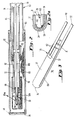
- the probe assembly 20 of Figure 1 is depicted in a side-sectioned view.
- the major purpose of the probe assembly 20 is to support and extend the electrochemical sensor cell 30 sufficiently far into the stack 24 to obtain a good reading while protecting the cell 30 from abrasive particles in the stack gases and cooling from the stack gas flow.
- the electrochemical sensor cell 30 is affixed by suitable means, such as a layer 68 of an electrically insulative ceramic cement, within the bore 69 of an extension tube 70.
- the tube 70 consists of an electrically insulating alumina tube section 72 of a convenient length so as to allow disassembly of the probe assembly 20 and the removal and/or replacement of the cell 30.
- the alumina tube section 72 is connected to a second extension tube section 74 of stainless steel or other suitable material by a Parker coupling 76 or other suitable means.
- the cell 30 and extension tube sections 72 and 74 are encased in a protective outer tube 80, formed in the preferred embodiments by lengths of stainless steel tubing 82 and 84 joined by a threaded Coupling 83 welded to tube section 84.
- a wire mesh screen 86 is provided at the open end of the tube 80 to admit stack gases and to retain an insulating material 96, only a portion of which is depicted.
- the screen 86 is held in position by appropriate means such as pins 88, one of which is depicted in Figure 2.
- the strips 106 cause the alternating current supplied by the power interface 56 to travel along the length of the first layer 37 and over the hemispherical portion 34 of the electrolyte 31.
- the first (outer) electrode layer 37 acts as a black body radiator.
- the rate of heat loss through radiation from the first (outer) electrode layer 37 is greater at the hemispherical portion 34 than along the length of the tubular portion 33 of the cell 30.
- the resistivity and power density of the first electrode layer 37 are effectively reduced at that end 34. Maximum heating therefore occurs in the region between the hemispherical portion 34 and the foil pads 52 and 54.
- the area of attachment of the bus strips 48 and 50 to the first electrode layer 37 is a potential source of high electrical resistance and therefore of excessive and undesirable heat generation. For this reason and to reduce the overall power requirements of the cell 30, it is suggested that the resistance per unit length of the outer electrode 35 in the region of the intermediate foil pads 52 and 54 and bus strips 48 and 50 be kept to a value less than about 1/10th that in the "active zone". This is substantially achieved by the foil pads 52 and 54 bonded to the first (outer) layer 37. If necessary, it is believed that further reduction in the resistance of the integral heater/electrode 35 can be achieved by overlaying the bus leads 48 and 50 with another layer of similar metal foil.
- the depicted embodiment of the cell 30 with integral heater/cell'electrode 35 is presently preferred for its superior performance given present fabrication constraints.
- Other electrode layer application techniques are being studied which may provide a means of controllably varying the thickness of the first electrode layer 37. When accomplished this may allow variation in the construction of the integral heater electrode 35 such as the elimination of the foil pads 50 and 52, the expansion of the active region or the use of even smaller electrolyte shapes.
- the calcia-stabilized zirconia appears to be more susceptible to electrolytic decomposition from an alternating electric voltage than does the yttria material.
- the calcia-stabilized electrolyte may be useful in a short operating life application and/or in a different electrode/electrolyte configuration where the reduced electrical conductivity of the calcia-stabilized zirconia might prevent undesired shorting of the heater alternating electric current.
- the most uniform coating results were obtained by dipping the electrolyte tube into the ink, slowly withdrawing it at a uniform rate and then rotating the tube in a furnace while drying.
- the frit is a lead oxide, titania, silica glass which crystallizes to form PbTi0 3 at about. 700°C and which melts at about 1100°C.
- Three such coatings were applied to the outer and inner surfaces of a zirconia substrate tube.
- bismuth trioxide in amounts of up to 10% by weight and preferably between about 1% and 5% by weight may be beneficially employed to form an oxygen porous integral heater/cell electrode layer.
- the bismuth trioxide appears to act as a flux, as does the gold.
- the amounts of bismuth trioxide and gold may be varied from the indicated amounts, at least to some extent, without deleterious effect on the characteristics of the resulting layer.
- the bismuth trioxide may be useful in forming electrode layers with base as well as noble metals, where base metals have heretofore been employed in the past.
- the discovered composition may be advantageously employed as a gas electrode material where an integral heater/electrode application is not needed by virtue of its ability to chemically bond the preferred platinum electrode material to a zirconia substrate in an oxygen porous layer.
- the shift in the average sensor emf developed due to the low frequency magnetic field surrounding the integral heater/electrode is in that direction (i.e., more negative) which is indicative of a lowering of the partial pressure of oxygen adjacent that heater/eiectrode.
- the 60 Hz current shifted the average emf by as much as about 225 millivolts. This necessitated following a repetitive heat first then measure cycle in using the early embodiments of the apparatus. It was discovered that as the frequency of the sinusoidal heating current is increased, the average value of the sensor potential shifts in the direction which is indicative of a more correct reading of the oxygen partial pressure at the heater/electrode. Above some sufficiently high frequency, the emf developed by the cell becomes stable and unaffected by the frequency of the heater current.
- thermal controller 42 temperature compensator circuit 43, timer circuit 62, modulator circuit 64, high frequency signal source 66 and power interface 56, which together act as a closed loop temperature control circuit for the cell 30.
- the set point input circuit 46 is optionally provided in order to adjust the operating temperature of the cell 30.
- a suitable voltage level signal might otherwise be generated by another circuit element to represent a fixed operating temperature for the cell 30.
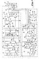
- thermocouple temperature compensation circuit 43 which includes a cold junction compensation diode (type IN916) 136, operational amplifier (type OP07), 137, capacitor 138, variable resistor 138a and fixed resistors 139 to 143.
- Screwheads 116 and 118 represent a circuit junction block to which the thermocouple leads 40 and 41 are connected.
- the diode 136 is, in reality, located at the junction block so as to be at an identical temperature to that of the negative (Alumel) thermocouple lead 41.
- the operational amplifier 137 accepts at its negative input, the voltage level signal on the positive (Chromel) lead 40 of the thermocouple 39 and a temperature compensated voltage level derived from the cold compensation diode 136.
- the thermal controller circuit 42 is formed by first and second operational amplifiers (type 347) 146 and 147 with related feedback circuits and resistors 144, 145 and 151 adjusting the gain of signals on lines 43a, 46a and 146a, respectively.
- the first operational amplifier 146 together with diode 148, capacitor 149 and resistances 150 and 151 form a novel combination deviation amplifier and two mode (percent proportional band and integral functions) controller.
- the room temperature compensated thermocouple voltage outputted on line 43a is combined with the set point voltage level signal outputted on lines 46a at junction 152 and the combined voltages, together with feedback voltages are fed into the negative input of the first operational amplifier 146.
- the set point circuit and temperature compensation circuit voltage level signals are scaled for 5 millivolts/°C.
- the set point voltage level signal is the opposite polarity of that outputted by the compensation circuit amplifier 137 so that the algebraic sum of the output of the compensator circuit 43 and set point circuit 46, as computed by the amplifier 146, is equal to the proportional deviation error selected for optimal temperature control loop stability and desired whole temperature accuracy.
- the resistors 151 and 144 provide a fixed proportional band error (1%) which represents the allowable percentage difference between the voltage levels on lines 46a and 43a.
- Reset action occurs as a function of error integration across the capacitor 149.
- the combination of proportionalizing and reset action is selected to provide, in the preferred embodiment being described, optimal loop stability and whole temperature accuracy within ⁇ 1°C with expected oxygen sensor upsets.
- Diode 148 is provided to improve the response time of the two mode controller.
- the diode prevents the output of the amplifier 146 from rising much above zero, as would occur if there were a sudden call for a lower control temperature.
- the diode 148 reduces the integration requirement imposed on the capacitor 149 under such conditions allowing a faster return to control.
- the second operational amplifier 147 together with resistors 152 and 153 form a unity gain inverter which reverses the polarity of the output of the first amplifier 146 for driving the modulator circuit 64.
- the output of the timer 62 is passed via the line 62a to the modulator circuit 64 which includes the second timer element 162, capacitor 163 and variable resistor 164.
- the timer element 162 is formed by suitably wiring (starting from the upper left side of 162) the second reset, discharge, threshold, control voltage and output functions of the 556 integrated circuit timer.
- the capacitor 163 and variable resistor 164 determine the proportion of the 7 millisecond period for the output of the timer element 162 is high on line 64a.
- the resistor 164 is adjusted to provide for a maximum high output duration of 98% of the 7 millisecond pulse.
- the timer element 155 is connected as a free running oscillator.
- the timer element 162 is connected in a monostable mode so as to be triggered by the negative going edge of each of the consecutive pulses from the timer element 155.
- the threshold triggering voltage of the timer element 162 is further modulated by the voltage level signal passed from the thermal controller circuit 42 along the line 42a.
- the timer circuit 162 thus configured acts as a pulse width modulated oscillator. With consecutive pulses being ouput- ted by the timer element 155 at 7 millisecond intervals, the maximum pulse width of the high output level signal outputted by the timer element 162 is adjusted to 6.8 milliseconds by the variable resistor 164 with a threshold voltage of 12.5 supplied from the thermal controller circuit 42.
- the circuit 66 is formed by an integrated circuit timer 166 (type 555), variable resistor 167, diodes 168 and 169, capacitors 170 and 171 and fixed resistance 172.
- the timer 166 is also wired as a free running oscillator generating a square wave output signal fluctuating between levels of about 0 and +15 volts at a frequency of 50 kHz.
- the output of the oscillator 162 is switched on and off by applying the width modulated pulses outputted by the modulator circuit 64 on line 64a to the reset function of the type 555 timer element 166.
- the frequency of the output of the timer circuit 166 is determined by the combination of capacitor 170 and resistors 167 and 172.
- the cell 330 is again heated by resistively heating one or both of the electrode layers 337 and 336.
- a high frequency current source 342 is connected by means of bus leads 344 and 346 to circular terminals 348 and 350 at opposing ends 332 and 333 of the inner electrode layer 337.
- the inner electrode 337 is electrically connected with the outer electrode 336 across a potentiometer 352 or other high impedance circuit for responding to the emf developed by cell 330.
Landscapes
- Chemical & Material Sciences (AREA)
- Life Sciences & Earth Sciences (AREA)
- Health & Medical Sciences (AREA)
- Physics & Mathematics (AREA)
- Chemical Kinetics & Catalysis (AREA)
- Electrochemistry (AREA)
- Molecular Biology (AREA)
- Analytical Chemistry (AREA)
- Biochemistry (AREA)
- General Health & Medical Sciences (AREA)
- General Physics & Mathematics (AREA)
- Immunology (AREA)
- Pathology (AREA)
- Measuring Oxygen Concentration In Cells (AREA)
- Hybrid Cells (AREA)
Claims (14)
Priority Applications (1)
| Application Number | Priority Date | Filing Date | Title |
|---|---|---|---|
| AT84301044T ATE44618T1 (de) | 1983-02-18 | 1984-02-17 | Erhitzte elektrochemische messzelle. |
Applications Claiming Priority (4)
| Application Number | Priority Date | Filing Date | Title |
|---|---|---|---|
| US46781283A | 1983-02-18 | 1983-02-18 | |
| US467812 | 1983-02-18 | ||
| US48809483A | 1983-04-25 | 1983-04-25 | |
| US488094 | 1983-04-25 |
Publications (2)
| Publication Number | Publication Date |
|---|---|
| EP0117692A1 EP0117692A1 (de) | 1984-09-05 |
| EP0117692B1 true EP0117692B1 (de) | 1989-07-12 |
Family
ID=27042191
Family Applications (1)
| Application Number | Title | Priority Date | Filing Date |
|---|---|---|---|
| EP84301044A Expired EP0117692B1 (de) | 1983-02-18 | 1984-02-17 | Erhitzte elektrochemische Messzelle |
Country Status (5)
| Country | Link |
|---|---|
| EP (1) | EP0117692B1 (de) |
| KR (1) | KR840007709A (de) |
| AU (1) | AU575551B2 (de) |
| DE (1) | DE3478955D1 (de) |
| DK (1) | DK75984A (de) |
Families Citing this family (5)
| Publication number | Priority date | Publication date | Assignee | Title |
|---|---|---|---|---|
| US4875990A (en) * | 1986-08-28 | 1989-10-24 | Ngk Insulators, Ltd. | Oxygen concentration measuring device |
| US4784728A (en) * | 1987-06-23 | 1988-11-15 | Ametek, Inc. | Oxygen measuring apparatus and method with automatic temperature compensation |
| WO1993022892A1 (en) * | 1992-05-07 | 1993-11-11 | Misra Asoka K | Method and apparatus for conversion of electrical energy to heat |
| FR2735866B1 (fr) * | 1995-06-22 | 1997-08-29 | Crevoiserat Jean Michel | Sonde pour mesurer la pression partielle d'oxygene dans les cheminees domestiques et industrielles |
| US6228252B1 (en) * | 1997-02-13 | 2001-05-08 | Ngk Spark Plug Co. Ltd. | Apparatus for detecting concentration of nitrogen oxide |
Citations (1)
| Publication number | Priority date | Publication date | Assignee | Title |
|---|---|---|---|---|
| EP0108179A1 (de) * | 1982-10-08 | 1984-05-16 | Ngk Insulators, Ltd. | Elektrochemische Messvorrichtung, Messzelle und Verfahren zur Verwendung derselben |
Family Cites Families (4)
| Publication number | Priority date | Publication date | Assignee | Title |
|---|---|---|---|---|
| US4407704A (en) * | 1979-12-04 | 1983-10-04 | Ngk Insulators, Ltd. | Oxygen concentration detector and a method of detecting oxygen concentration |
| JPS57200844A (en) * | 1981-06-04 | 1982-12-09 | Ngk Insulators Ltd | Oxygen concentration detector |
| CA1164946A (en) * | 1981-06-15 | 1984-04-03 | Alex D. Colvin | Method of precisely controlling the temperature of an oxygen sensor |
| DE3127472A1 (de) * | 1981-07-11 | 1983-01-20 | Brown, Boveri & Cie Ag, 6800 Mannheim | "elektrochemische messzelle" |
-
1984
- 1984-02-15 AU AU24628/84A patent/AU575551B2/en not_active Ceased
- 1984-02-16 KR KR1019840000755A patent/KR840007709A/ko not_active Withdrawn
- 1984-02-17 DE DE8484301044T patent/DE3478955D1/de not_active Expired
- 1984-02-17 EP EP84301044A patent/EP0117692B1/de not_active Expired
- 1984-02-17 DK DK75984A patent/DK75984A/da not_active Application Discontinuation
Patent Citations (1)
| Publication number | Priority date | Publication date | Assignee | Title |
|---|---|---|---|---|
| EP0108179A1 (de) * | 1982-10-08 | 1984-05-16 | Ngk Insulators, Ltd. | Elektrochemische Messvorrichtung, Messzelle und Verfahren zur Verwendung derselben |
Also Published As
| Publication number | Publication date |
|---|---|
| KR840007709A (ko) | 1984-12-10 |
| AU2462884A (en) | 1984-08-23 |
| AU575551B2 (en) | 1988-08-04 |
| EP0117692A1 (de) | 1984-09-05 |
| DE3478955D1 (en) | 1989-08-17 |
| DK75984A (da) | 1984-08-19 |
| DK75984D0 (da) | 1984-02-17 |
Similar Documents
| Publication | Publication Date | Title |
|---|---|---|
| US4659435A (en) | Integrally heated electrochemical cell method and apparatus | |
| US4500412A (en) | Oxygen sensor with heater | |
| US4543176A (en) | Oxygen concentration detector under temperature control | |
| US6592731B1 (en) | Amperometric oxygen sensor | |
| US4207159A (en) | Apparatus for measurement of oxygen concentration | |
| CA1155494A (en) | Oxygen concentration detector and a method of detecting oxygen concentration | |
| JPH0113530B2 (de) | ||
| EP1566630A1 (de) | Gasdetektor | |
| US4644138A (en) | Temperature control system with simplified controller and power supply | |
| US4541900A (en) | Method for heating solid electrolyte | |
| CA1095989A (en) | Solid electrolyte sensor for monitoring combustibles in an oxygen containing environment | |
| JPH0113531B2 (de) | ||
| EP0117692B1 (de) | Erhitzte elektrochemische Messzelle | |
| CA1104654A (en) | Resistor-type solid electrolyte oxygen sensor | |
| CA1201768A (en) | Electrochemical device, cell and a method of operating the same | |
| US4548680A (en) | Method for determining the partial pressure of oxygen in an atmosphere | |
| CA1225434A (en) | Method and apparatus for integrally heated electrochemical sensors | |
| EP0038078B1 (de) | Gas Detektor | |
| EP0067437A1 (de) | Sauerstoffsensor und Bedienungsmethode | |
| CA1216027A (en) | Electrochemical cell with integral heater/electrode | |
| JPH01201149A (ja) | 複合ガスセンサ | |
| US5871633A (en) | Impedance type humidity sensor with protonconducting electrolyte and method of using same | |
| JPH06242060A (ja) | 炭化水素センサ | |
| Makovos et al. | Development of a solid electrolyte sensor for oxygen in hot gases | |
| JPH049258B2 (de) |
Legal Events
| Date | Code | Title | Description |
|---|---|---|---|
| PUAI | Public reference made under article 153(3) epc to a published international application that has entered the european phase |
Free format text: ORIGINAL CODE: 0009012 |
|
| AK | Designated contracting states |
Designated state(s): AT BE CH DE FR GB IT LI NL SE |
|
| 17P | Request for examination filed |
Effective date: 19850122 |
|
| 17Q | First examination report despatched |
Effective date: 19860321 |
|
| RAP1 | Party data changed (applicant data changed or rights of an application transferred) |
Owner name: DIDIER-WERKE AG |
|
| GRAA | (expected) grant |
Free format text: ORIGINAL CODE: 0009210 |
|
| AK | Designated contracting states |
Kind code of ref document: B1 Designated state(s): AT BE CH DE FR GB IT LI NL SE |
|
| REF | Corresponds to: |
Ref document number: 44618 Country of ref document: AT Date of ref document: 19890715 Kind code of ref document: T |
|
| REF | Corresponds to: |
Ref document number: 3478955 Country of ref document: DE Date of ref document: 19890817 |
|
| ITF | It: translation for a ep patent filed | ||
| ET | Fr: translation filed | ||
| PLBE | No opposition filed within time limit |
Free format text: ORIGINAL CODE: 0009261 |
|
| STAA | Information on the status of an ep patent application or granted ep patent |
Free format text: STATUS: NO OPPOSITION FILED WITHIN TIME LIMIT |
|
| 26N | No opposition filed | ||
| ITTA | It: last paid annual fee | ||
| PGFP | Annual fee paid to national office [announced via postgrant information from national office to epo] |
Ref country code: DE Payment date: 19930215 Year of fee payment: 10 |
|
| PGFP | Annual fee paid to national office [announced via postgrant information from national office to epo] |
Ref country code: GB Payment date: 19940208 Year of fee payment: 11 |
|
| PGFP | Annual fee paid to national office [announced via postgrant information from national office to epo] |
Ref country code: FR Payment date: 19940210 Year of fee payment: 11 |
|
| PGFP | Annual fee paid to national office [announced via postgrant information from national office to epo] |
Ref country code: AT Payment date: 19940214 Year of fee payment: 11 |
|
| PGFP | Annual fee paid to national office [announced via postgrant information from national office to epo] |
Ref country code: CH Payment date: 19940215 Year of fee payment: 11 |
|
| PGFP | Annual fee paid to national office [announced via postgrant information from national office to epo] |
Ref country code: SE Payment date: 19940216 Year of fee payment: 11 |
|
| PGFP | Annual fee paid to national office [announced via postgrant information from national office to epo] |
Ref country code: NL Payment date: 19940228 Year of fee payment: 11 |
|
| PGFP | Annual fee paid to national office [announced via postgrant information from national office to epo] |
Ref country code: BE Payment date: 19940408 Year of fee payment: 11 |
|
| PG25 | Lapsed in a contracting state [announced via postgrant information from national office to epo] |
Ref country code: DE Effective date: 19941101 |
|
| EAL | Se: european patent in force in sweden |
Ref document number: 84301044.8 |
|
| PG25 | Lapsed in a contracting state [announced via postgrant information from national office to epo] |
Ref country code: GB Effective date: 19950217 Ref country code: AT Effective date: 19950217 |
|
| PG25 | Lapsed in a contracting state [announced via postgrant information from national office to epo] |
Ref country code: SE Effective date: 19950218 |
|
| PG25 | Lapsed in a contracting state [announced via postgrant information from national office to epo] |
Ref country code: LI Effective date: 19950228 Ref country code: CH Effective date: 19950228 Ref country code: BE Effective date: 19950228 |
|
| BERE | Be: lapsed |
Owner name: DIDIER-WERKE A.G. Effective date: 19950228 |
|
| PG25 | Lapsed in a contracting state [announced via postgrant information from national office to epo] |
Ref country code: NL Effective date: 19950901 |
|
| GBPC | Gb: european patent ceased through non-payment of renewal fee |
Effective date: 19950217 |
|
| PG25 | Lapsed in a contracting state [announced via postgrant information from national office to epo] |
Ref country code: FR Effective date: 19951031 |
|
| NLV4 | Nl: lapsed or anulled due to non-payment of the annual fee |
Effective date: 19950901 |
|
| EUG | Se: european patent has lapsed |
Ref document number: 84301044.8 |
|
| REG | Reference to a national code |
Ref country code: FR Ref legal event code: ST |