EP1566548B1 - Rotationspumpe - Google Patents
Rotationspumpe Download PDFInfo
- Publication number
- EP1566548B1 EP1566548B1 EP05250809A EP05250809A EP1566548B1 EP 1566548 B1 EP1566548 B1 EP 1566548B1 EP 05250809 A EP05250809 A EP 05250809A EP 05250809 A EP05250809 A EP 05250809A EP 1566548 B1 EP1566548 B1 EP 1566548B1
- Authority
- EP
- European Patent Office
- Prior art keywords
- casing
- rotary pump
- annular
- inlet
- pump
- Prior art date
- Legal status (The legal status is an assumption and is not a legal conclusion. Google has not performed a legal analysis and makes no representation as to the accuracy of the status listed.)
- Ceased
Links
- 230000015572 biosynthetic process Effects 0.000 claims description 23
- 238000005755 formation reaction Methods 0.000 claims description 23
- 238000007789 sealing Methods 0.000 claims description 14
- 238000011144 upstream manufacturing Methods 0.000 claims description 13
- 238000000034 method Methods 0.000 claims description 12
- 239000002002 slurry Substances 0.000 claims description 10
- 230000002093 peripheral effect Effects 0.000 claims description 8
- 238000000465 moulding Methods 0.000 claims description 7
- JOYRKODLDBILNP-UHFFFAOYSA-N Ethyl urethane Chemical compound CCOC(N)=O JOYRKODLDBILNP-UHFFFAOYSA-N 0.000 claims description 5
- 229920001971 elastomer Polymers 0.000 claims description 5
- 239000012530 fluid Substances 0.000 claims description 5
- 239000000463 material Substances 0.000 claims description 4
- 125000006850 spacer group Chemical group 0.000 claims description 4
- 230000010339 dilation Effects 0.000 claims description 2
- 230000004323 axial length Effects 0.000 description 2
- 238000005266 casting Methods 0.000 description 2
- 239000002131 composite material Substances 0.000 description 2
- 238000010276 construction Methods 0.000 description 2
- 238000005086 pumping Methods 0.000 description 2
- 239000007787 solid Substances 0.000 description 2
- 229910000831 Steel Inorganic materials 0.000 description 1
- 238000005299 abrasion Methods 0.000 description 1
- 239000011324 bead Substances 0.000 description 1
- 238000004891 communication Methods 0.000 description 1
- 238000013016 damping Methods 0.000 description 1
- 230000018109 developmental process Effects 0.000 description 1
- 238000006073 displacement reaction Methods 0.000 description 1
- 230000000694 effects Effects 0.000 description 1
- 239000013013 elastic material Substances 0.000 description 1
- 239000000806 elastomer Substances 0.000 description 1
- 238000007667 floating Methods 0.000 description 1
- 239000003292 glue Substances 0.000 description 1
- 239000000203 mixture Substances 0.000 description 1
- 230000000750 progressive effect Effects 0.000 description 1
- 238000009877 rendering Methods 0.000 description 1
- 239000010959 steel Substances 0.000 description 1
- 238000003466 welding Methods 0.000 description 1
Images


Classifications
-
- F—MECHANICAL ENGINEERING; LIGHTING; HEATING; WEAPONS; BLASTING
- F04—POSITIVE - DISPLACEMENT MACHINES FOR LIQUIDS; PUMPS FOR LIQUIDS OR ELASTIC FLUIDS
- F04D—NON-POSITIVE-DISPLACEMENT PUMPS
- F04D29/00—Details, component parts, or accessories
- F04D29/08—Sealings
- F04D29/16—Sealings between pressure and suction sides
- F04D29/165—Sealings between pressure and suction sides especially adapted for liquid pumps
- F04D29/167—Sealings between pressure and suction sides especially adapted for liquid pumps of a centrifugal flow wheel
-
- F—MECHANICAL ENGINEERING; LIGHTING; HEATING; WEAPONS; BLASTING
- F04—POSITIVE - DISPLACEMENT MACHINES FOR LIQUIDS; PUMPS FOR LIQUIDS OR ELASTIC FLUIDS
- F04D—NON-POSITIVE-DISPLACEMENT PUMPS
- F04D29/00—Details, component parts, or accessories
- F04D29/08—Sealings
- F04D29/086—Sealings especially adapted for liquid pumps
-
- F—MECHANICAL ENGINEERING; LIGHTING; HEATING; WEAPONS; BLASTING
- F04—POSITIVE - DISPLACEMENT MACHINES FOR LIQUIDS; PUMPS FOR LIQUIDS OR ELASTIC FLUIDS
- F04D—NON-POSITIVE-DISPLACEMENT PUMPS
- F04D29/00—Details, component parts, or accessories
- F04D29/40—Casings; Connections of working fluid
- F04D29/42—Casings; Connections of working fluid for radial or helico-centrifugal pumps
- F04D29/426—Casings; Connections of working fluid for radial or helico-centrifugal pumps especially adapted for liquid pumps
- F04D29/4286—Casings; Connections of working fluid for radial or helico-centrifugal pumps especially adapted for liquid pumps inside lining, e.g. rubber
-
- F—MECHANICAL ENGINEERING; LIGHTING; HEATING; WEAPONS; BLASTING
- F04—POSITIVE - DISPLACEMENT MACHINES FOR LIQUIDS; PUMPS FOR LIQUIDS OR ELASTIC FLUIDS
- F04D—NON-POSITIVE-DISPLACEMENT PUMPS
- F04D29/00—Details, component parts, or accessories
- F04D29/60—Mounting; Assembling; Disassembling
- F04D29/62—Mounting; Assembling; Disassembling of radial or helico-centrifugal pumps
- F04D29/622—Adjusting the clearances between rotary and stationary parts
Definitions
- THIS invention relates to a rotary pump, especially a centrifugal pump, using an annular bridge for bridging an annular gap between two adjacent annular components of a rotary pump and methods of adjusting the configuration of a rotary pump.
- US 5,941,536 discloses an elastomer seal member for use in a pump having adjustable side liners structured with a bellows type flange which provides and maintains a tight seal between adjoining casing elements of the pump as the side liners are axially adjusted to compensate for wear and abrasion of the side liners.
- a method of adjusting a configuration of a rotary pump including axially adjusting an end portion of a casing at a suction end of the pump relative to a remainder or main portion of the casing and relative to an inlet flange of the pump, the method including displacing the end portion of the casing relative to the remainder of the casing along a peripheral seal interface, characterized in that the method includes displacing the end portion of the casing relative to the inlet flange at a break in an inlet conduit intermediate said inlet flange and an impeller cavity, the break being bridged by an axially adjustable annular bridging ring, wherein the end portion has at its inner periphery a tubular stub providing an inlet port leading to the impeller cavity and being aligned with and complemental to said inlet conduit, said inlet conduit being an upstream tubular section and said tubular stub being a downstream tubular section.
- the method is a method of adjusting a running clearance in the rotary pump between the inlet or suction end of the casing and an impeller, the end portion of the casing is adjusted relative to the impeller and correspondingly to the rest of the casing, the end portion slides at a radially outer periphery thereof relative to the rest of the casing, and moves at a radially inner periphery thereof relative to said inlet flange, the break is a varying gap between the inlet flange and the radially inner periphery of the end portion, and the bridging ring is axially expansible and contractable.
- the invention thus provides for holding the main casing portion, and the inlet portion with piping connected thereto, stationary, while rendering said end portion floating to allow adjustment thereof to set it relative to a side of the impeller and to allow progressive axial adjustment thereof to compensate for wear or to take up wear along a corresponding end of the impeller.
- a casing for a rotary pump which pump casing is in the form of an assembly including
- the adjustable component may be integral. It may be in the form of a casting, e.g. a steel casting when the casing is for a slurry pump.
- the annular bridge may be in the form of a seal for providing sealing between the tubular inlet and the annular adjustable component.
- the, casing may include a seal arranged functionally in parallel with the annular bridge, for sealing between the tubular Inlet and the annular adjustable component.
- the invention extends to a rotary pump including a casing in accordance with the third aspect and an impeller rotatable within the casing.
- the rotary pump may be in the form of a centrifugal pump. It may be in the form of a slurry pump.
- the annular bridge may include opposed annular seat formations seated on the respective annular seats, and an elastic spacer biasing the respective seat formations away from each other and being elastically collapsible and dilatable to allow the variable gap between the seat formations to be closed.
- the elastic spacer may include a plurality of peripherally spatially arranged elastic links.
- the links may be fast with and span between the respective seat formations.
- the links may be configured and arranged elastically to hinge to cause collapse and to unhinge to cause dilation. Hinging and unhinging may be generally tangentially about generally radial axes. Hinging and unhinging may be effected by relative rotation between the seat formations.
- the bridge may include a flexible seal formation extending between the seat formations to cause the bridge to perform a seal function.
- the bridge may be in the form of a moulding of synthetic polymeric material.
- the synthetic polymeric material may be selected from rubber and urethane, which has deformation/stress characteristics within the following range:
- An alternative annular bridge may include opposed annular upstream and downstream seat formations seated on the respective annular seats, and an annular body having the upstream and downstream seat formations and comprising a plurality of elastic rings, each having a rounded channel-shaped cross-section which is shaped and dimensioned annularly to nest into one-another, the rings being interconnected such as to be relatively fixed along radially inner extremities, and to be rollable over one-another along radially outer portions.
- the rings may be of urethane, having surfaces conducive to sliding over one-another with little friction.
- the rings may be in the form of separate mouldings fixedly interconnected along the inner peripheries only. Said interconnected inner peripheries may then provide said upstream seat formation, which may be in the form of a flange to allow location in a complemental seat of the inlet, the downstream seat formation seating merely abuttingly on the downstream seat.
- a rotary slurry pump in accordance with this invention is generally indicated by reference numeral 10.
- the slurry pump 10 is generally symmetrical (except for a volute and an outlet flange thereof) to a centre line generally indicated by reference numeral 11. Only one half of the pump, to one side of the centre line 11, is shown in axial section.
- the pump 10 comprises a pump casing generally indicated by reference numeral 12 and providing an inlet generally indicated by reference numeral 14, and an impeller cavity and volute generally indicated by reference numeral 16 for accommodating a rotary impeller 18. An outlet in communication with the volute is not shown in the drawing.
- the impeller 18 is carried on a rotary shaft 20 by means of which the impeller is rotated in use within the stationary casing 12.
- Sealing is required along the end of the casing 12 corresponding to the position of the shaft 20, and which is generally referred to as the dry end or the drive end.
- the sealing is generally indicated by reference numeral 22. It is of composite structure and is not further described.
- This invention is concerned with the construction of the pump 10, and more specifically the casing 12, at the opposed end which is generally referred to as the suction end.
- the casing 12 is a composite casing comprising a main casing portion 24, and opposed end liners, respectively a drive end liner generally indicated by reference numeral 25, with which this invention is not concerned, and a suction end liner 28.
- the main casing portion 24 is in the form of a peripheral cap, and the drive end liner 25 and suction end liner 28 are in the form of rings.
- the main casing portion 24 and the suction end liner 28 provide opposing seats 26, 30 for a ring seal 32 having a generally tapering cross section, tapering toward a free inner end proximate the impeller cavity and volute 16.
- the seat 30 is concentric to allow slidable displacement in an axial direction of the suction end liner 28 relative to the main casing portion 24.
- the suction end liner 28 has a ring 34 providing with the main casing portion 24 one end of the impeller cavity and volute 16.
- the suction end liner 28 further has a short tubular portion 36 at a radially inner extremity thereof and which opens into the centre of the impeller cavity 16. It has an upstream seat 38.
- the inlet 14 is provided by a tubular inlet portion 40 having, at a free end thereof, a flange 42 for connection to piping feeding slurry to the rotary slurry pump 10 in use, and a tubular portion having, at a downstream end thereof, a seat 44 opposing the seat 38 of the tubular portion 36.
- a bridge cavity or sealing cavity for an annular bridge 50 in accordance with the invention.
- the casing 12 In use, the casing 12 generally, and more specifically the main casing portion 24, remains stationary. Furthermore, the tubular inlet portion 40, being connected to stationary piping, remains stationary or rigid. However, especially at the suction end of the impeller 18, it is subjected to high wear which erodes the suction end of the impeller 18 and also the corresponding face of the ring 34 and the downstream end of the tubular section 36. if such wear is not addressed, an inappropriately large gap develops between the end of the impeller 18 and the corresponding face of the ring 34, which leads to several undesired effects, mostly relating ultimately to reduced pumping efficiency.
- the Applicant proposes adjusting the axial position of the suction end liner 28 continually to ensure an appropriately small gap between the end of the impeller 18 and the face of the suction end liner 28.
- this is achieved by having the suction end liner 28 adjustable axially as indicated by arrow 48 by means of an adjustment mechanism 46. Adjustment is made possible by allowing sliding of the suction end liner 28 via the seal ring 32 relative to the main casing portion 24, and by providing the annular bridge 50 as an expanding bridge which continually expands to fill the gap between the seats 38 and 44. in some embodiments the bridge 50 will provide sealing, and in other embodiments a separate or an auxiliary sealing mechanism is provided.
- the invention thus has the advantage that wear in a particularly high wearing area can be compensated for without adjustment in the axial position of the main casing portion 24 and without adjustment in the position of the piping and the connection of the piping to the casing 12.
- suction end liner 28 which is prone to high wear, can be replaced independently of the main casing portion 24 and of the peripheral Inlet portion 40.
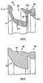
- the bridge is generally indicated by reference numeral 50, and is in the form of an integral moulding of elastic material, advantageously rubber, or urethane.
- the annular bridge 50 comprises a first ring 52, an axially spaced second ring 54 defining, generally, an annular gap therebetween, indicated by reference numeral 56. At one side, the annular gap 56 is closed by means of a flexible, solid apron 58 preventing flow of fluid through the annular gap 56.
- the first and second rings 52, 54 are collapsibly interconnected by a plurality of longitudinally and radially oriented links 60, which are peripherally spaced to provide gaps therebetween.
- the apron 58 is flexible to a high degree, and the links 60 are elastic.
- the annular bridge 50 is in the form of an integral or unitary moulding of rubber.
- the first ring 52 has an outer face 52.1 which is generally curved, and which blends into a flat annular face 52.2 at a radially outer and axially outer extremity thereof.
- the second ring 54 Along an inner periphery of the second ring 54, it has a peripheral rounded ridge in the form of a bead 54.1. Along an outer periphery of the second ring 54, it is peripherally indented to form a shallow channel 54.2.
- the links 60 which form hinges in accordance with the invention, are hinged effectively to collapse within the gap 56 and thus to shorten the axial length of the bridge 50.
- the bridge 50 is collapsed as explained above for receipt between the seats 38, 44.
- the elastic links 60 rotate progressively back from their collapsed to their erect conditions to lengthen or dilate the bridge 50 and to ensure that the gap between the seats 38 and 44 remains filled.
- the second ring 54 is conveniently located in position in one of the seats 38, 44 and the first ring 52 seats against the other of the seats 38, 44.
- the apron 58 which is flexible but continuous or solid, prevents flow or leakage through the annular gap 56.
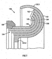
- the seal 150 comprises a plurality of rings having curved cross-sections as shown at 152, 154, 156, 158 and 160.
- the rings. 152 to 160 are in the form of mouldings of urenthane having surfaces with low friction characteristics to be conducive to ease of sliding across one-another.
- the rings have curved bodies with tangential extensions extending axially along their Inner peripheries.
- the rings 154, 156, 158 and 160 have radially outer free ends terminating adjacent one-another.
- the ring 152 has a projecting or extended free end portion 152.1 projecting well beyond the extremities of the other rings.
- the ring 152 further has, at its radially inner end, a radially inwardly projecting flange 152.2.
- the rings 154 to 158 have progressively longer axial extensions along their inner peripheries to form a stepped configuration, whereas the innermost ring 160 has a slightly truncated axial extension to accommodate a rebated seating ring 166. All of the rings are fixed at their radially inner ends, for example by an appropriate glue, welding, or the like.
- the seal 150 is shown received within the sealing cavity between the seats 38, 44.
- the seal 150 is located in the seat 44 via the seating ring 166 which seats snugly in a stepped or rebated portion of the seat 44.
- the seat 38 has, at its inner periphery, a projecting annular nose 38.1, the seal 150 being received radially outwardly of the nose 38.1 and merely abuts a flat portion of the seat 38 radially outwardly of the nose 38.1.
- An annular liner clamping ring 33 by means of an axially projecting flange 33.1 at an inner periphery, closes the sealing cavity defined between the seats 38, 44.
- the free projecting portion 152.1 of the outermost ring 152 abuts an inner periphery of the liner damping ring flange 33.1
- the liner clamping ring flange 33.1 In the radially inner periphery of the liner clamping ring flange 33.1, it has an annular seal cavity which is open along its radially inner extremity for receiving an O-ring seal 70, against which the ring 152 of the seal 150 abuts.
- the seal 150 is located in the seat 44. Initially, the seat 38 is relatively close to the seat 44 thus requiring the rings 152 to 160 to roll over one-another to shorten the axial length of the seal 150 to match the small annular gap between the seats 38 and 44.
- the suction end liner 34 is progressively axially displaced to close the gap caused by wear thus opening up the gap between the seats 38 and 44.
- the rings 152 to 160 being resilient, roll open to continue to fill the gap and thus to bridge the gap to prevent inflow of working fluid into the seal cavity.
- Sealing is effected by means of the seals 70, 72.
- the invention has the advantage that an axially expandable annular bridge is provided to bridge an annular gap between axially adjustable annular components.
Landscapes
- Engineering & Computer Science (AREA)
- Mechanical Engineering (AREA)
- General Engineering & Computer Science (AREA)
- Structures Of Non-Positive Displacement Pumps (AREA)
Claims (23)
- Verfahren zum Verstellen einer Konfiguration einer Rotationspumpe (10) unter Einbeziehung der axialen Verstellung eines Endabschnitts (28) eines Gehäuses (12) an einer Saugseite der Pumpe bezüglich eines restlichen oder Hauptabschnitts (24) des Gehäuses und bezüglich eines Einlassflanschs (42) der Pumpe, wobei das Verfahren das Verschieben des Endabschnitts (28) des Gehäuses (12) bezüglich des restlichen Abschnitts des Gehäuses (12) entlang einer umlaufenden Dichtgrenzfläche (30) umfasst, dadurch gekennzeichnet, dass das Verfahren das Verschieben des Endabschnitts (28) des Gehäuses bezüglich des Einlassflanschs (42) an einer Unterbrechung in einer Einlassleitung (40) zwischen diesem Einlassflansch (42) und einem Impellerhohlraum (16) umfasst, wobei die Unterbrechung durch einen axial verstellbaren Überbrückungsring (50) überbrückt wird, wobei der Endabschnitt (28) an seinem inneren Umfang einen rohrförmigen Stutzen (36) aufweist, der eine Eintrittsöffnung bereitstellt, die in den Impellerhohlraum (16) mündet und entsprechend der Einlassleitung (40) ausgerichtet und zu dieser komplementär ist, wobei diese Einlassleitung (40) ein leitungsaufseitiger rohrförmiger Abschnitt und der rohrförmige Stutzen (36) ein leitungsabwärtiger rohrförmiger Abschnitt ist.
- Verfahren nach Anspruch 1, wobei das Verfahren ein Verfahren zum Verstellen eines Laufspalts in der Rotationspumpe (10) zwischen der Einlass- oder Saugseite des Gehäuses (12) und einem Impeller (18) ist, der Endabschnitt (28) des Gehäuses (12) bezüglich des Impellers (18) und dementsprechend bezogen auf den Rest des Gehäuses (12) verstellt wird, der Endabschnitt (28) an einem radial äußeren Umfangsbereich bezogen auf den Rest des Gehäuses gleitet und sich an einem radial inneren Umfangsbereich bezogen auf den Einlassflansch (42) bewegt, die Unterbrechung ein veränderlicher Spalt zwischen dem Einlassflansch (42) und dem radial inneren Umfangsbereich des Endabschnitts (28) ist und der Überbrückungsring (50) axial ausdehnbar und zusammenziehbar ist.
- Gehäuse (12) für eine Rotationspumpe (10), wobei das Pumpengehäuse als Baugruppe ausgeführt ist mit:einem peripheren Hauptteil des Gehäuses (24), der ein Spiralgehäuse und einen Impellerhohlraum (16) für Pumpgut begrenzt;einem rohrförmigen Einlass (14), der einen Einlassflansch (42) zur Verbindung mit Einlassrohrwerk für die Pumpe und einen rohrförmigen Abschnitt (40) aufweist, der sich von dem Flansch bis zu dem von dem Pumpengehäuse definierten Impellerhohlraum (16) erstreckt, wobei der rohrförmige Abschnitt nahe an dem Impellerhohlraum endet;einem ringförmigen verstellbaren Bauteil (28) mit einem Ring (34), der zu dem Hauptteil (24) des Gehäuses komplementär ist, um den Impellerhohlraum (16) zu begrenzen und mit einer Einlassöffnung, die dem rohrförmigen Abschnitt (40) entsprechend ausgerichtet und zu diesem komplementär ist und in den Impellerhohlraum mündet;einem Verstellmechanismus (46) zum wahlweisen, verstellbaren Verschieben des verstellbaren Bauteils bezogen auf den Hauptteil des Gehäuses und den Einlass;dadurch GEKENNZEICHNET, dass das verstellbare Bauteil (28) an seinem inneren Umfang einen rohrförmigen Stutzen (36) aufweist, der die Einlassöffnung bereitstellt und entsprechend dem rohrförmigen Abschnitt (40) ausgerichtet und zu diesem komplementär ist, wobei der rohrförmige Abschnitt ein leitungsaufseitiger rohrförmiger Abschnitt und der rohrförmige Stutzen ein leitungsabwärtiger rohrförmiger Abschnitt ist und durchkomplementäre ringförmige Sitze (26, 30) an dem Hauptteil (22) des Gehäuses und an dem ringförmigen verstellbaren Bauteil (28), um zwischen diesen eine Dichtung (32) zur Ausbildung einer axial verstellbaren Grenzfläche zwischen dem Hauptteil des Gehäuses und dem verstellbaren Bauteil aufzunehmen und durchgegenüberliegende ringförmige Sitze (38, 44) an einem freien Ende des rohrförmigen Stutzens (36) des verstellbaren Bauteils (28) und [einem freien Ende] des Einlasses (14) zur Aufnahme einer expandierbaren ringförmigen Überbrückung (50), um die axiale Verstellung zwischen dem verstellbaren Bauteil und dem Einlass zu ermöglichen.
- Rotationspumpengehäuse nach Anspruch 3,
dadurch GEKENNZEICHNET, dass das den Ring (34) und den rohrförmigen Stutzen (36) umfassende verstellbare Bauteil (28) einstückig ist. - Rotationspumpengehäuse nach Anspruch 3 oder 4,
dadurch GEKENNZEICHNET, dass die ringförmige Überbrückung (50) zum Dichten zwischen dem rohrförmigen Einlass (14) und dem rohrförmigen Stutzen (36) als Dichtung ausgebildet ist. - Rotationspumpengehäuse nach Anspruch 5,
dadurch GEKENNZEICHNET, dass die ringförmige Überbrückung (50) auf die jeweils gegenüberliegenden ringförmigen Sitze (38, 44) aufgesetzte gegenüberliegende Sitzausbildungen (52.2,54) umfasst und einen elastischen Abstandshalter (58, 60), der die entsprechenden Sitzausbildungen gegeneinander vorspannt und der elastisch zusammenfaltbar und ausdehnbar ist, um das Verschließen des veränderbaren Spalts 5 zwischen den Sitzausbildungen zu ermöglichen. - Rotationspumpengehäuse nach Anspruch 6,
dadurch GEKENNZEICHNET, dass der elastische Abstandshalter (58, 60) eine Vielzahl von räumlich peripher angeordneten elastischen Verbindungen (60) umfasst. - Rotationspumpengehäuse nach Anspruch 7,
dadurch GEKENNZEICHNET, dass die Verbindungen (60) fest mit den jeweiligen Sitzausbildungen verbunden und zwischen diesen ausgespannt sind. - Rotationspumpengehäuse nach Anspruch 8,
dadurch GEKENNZEICHNET, dass die Verbindungen (60) so ausgestaltet und angeordnet sind, dass sie elastisch faltbar sind, um ein Zusammenfalten zu bewirken und elastisch entfaltbar, um eine Ausdehnung zu bewirken. - Rotationspumpengehäuse nach Anspruch 9,
dadurch GEKENNZEICHNET, dass das Falten und Entfalten im Wesentlichen tangential um im Wesentlichen radiale Achsen erfolgt. - Rotationspumpengehäuse nach Anspruch 10,
dadurch GEKENNZEICHNET, dass das Falten und Entfalten durch Relatiwerdrehung zwischen den Sitzausbildungen vorgenommen wird. - Rotationspumpengehäuse nach einem der Ansprüche 6 bis 11,
dadurch GEKENNZEICHNET, dass die ringförmige Überbrückung eine flexible Dichtungsformation umfasst, die sich zwischen den Sitzausbildungen erstreckt, so dass die Überbrückung eine Dichtfunktion ausübt. - Rotationspumpengehäuse nach einem der Ansprüche 6 bis 12,
dadurch GEKENNZEICHNET, dass die Überbrückung in Form eines Presskörpers aus synthetischem Polymermaterial ausgeführt ist und dadurch, dass das synthetische Polymermaterial aus Gummi und Urethan ausgewählt ist, welches Verformungs-/Belastungseigenschaften in folgendem Bereich aufweist:bei einer Dehnung von 100% liegt die Belastung zwischen 1,8 und 3,4 N/mm2;bei einer Dehnung von 200% liegt die Belastung zwischen 4,8 und 8,7 N/mm2;bei einer Dehnung von 300% liegt die Belastung zwischen 9,6 und 16,1 N/mm2;bei einer Dehnung von 400% liegt die Belastung zwischen 16,2 und 25,6 N/mm2;bei einer Dehnung von 450% liegt die Belastung zwischen 20,2 und 31,1 N/mm2; - Rotationspumpengehäuse nach Anspruch 3 oder 4,
dadurch GEKENNZEICHNET, dass die ringförmige Überbrückung (150), die einen Spalt zwischen den gegenüberliegenden ringförmigen Sitzen (38, 44) überbrückt, durch eine Dichtung (33, 70, 72) abgeschlossen wird, die zur Abdichtung zwischen dem rohrförmigen Einlass (14) und dem ringförmigen verstellbaren Bauteil (28) funktionell parallel oder konzentrisch zu der ringförmigen Überbrückung angeordnet ist. - Rotationspumpengehäuse nach Anspruch 14,
dadurch GEKENNZEICHNET, dass die ringförmige Überbrückung (150) gegenüberliegende ringförmige leitungsaufseitige und leitungsabwärtige Sitzausbildungen (166,152), die auf den jeweiligen ringförmigen Sitzen (30, 44) aufliegen, umfasst und einen ringförmigen Körper mit den leitungsaufseitigen und leitungsabwärtigen Sitzausbildungen und umfassend eine Vielzahl von elastischen Ringen (152, 154, 156, 158, 160), die jeweils einen runden kanalförmigen Querschnitt aufweisen, der zum Ineinanderfügen ringförmig geformt und dimensioniert ist, wobei die Ringe derart miteinander verbunden sind, dass sie entlang radial innerer Enden relativ fest verbunden sind und entlang radial äußerer Teile übereinander gerollt werden können. - Rotationspumpengehäuse nach Anspruch 15,
dadurch GEKENNZEICHNET, dass die Ringe (152, 154, 156, 158, 160) aus Urethan sind und Oberflächen aufweisen, die für das Übereinandergleiten unter geringer Reibung förderlich sind. - Rotationspumpengehäuse nach Anspruch 15 oder 16,
dadurch GEKENNZEICHNET, dass die Ringe als separate Formkörper, die nur entlang der Innenumfänge fest miteinander verbunden sind (164,166), ausgebildet sind. - Rotationspumpengehäuse nach Anspruch 17,
dadurch GEKENNZEICHNET, dass die miteinander verbundenen Innenumfänge (164, 166) die leitungsaufseitige Sitzausbildung bereitstellen. - Rotationspumpengehäuse nach einem der Ansprüche 15 bis 18,
dadurch GEKENNZEICHNET, dass die leitungsaufseitige Sitzausbildung als Flansch (166) ausgebildet ist, um das Einsetzen in einen komplementären Sitz (44) des Einlasses zu ermöglichen, wobei die leitungsabwärtige Sitzausbildung lediglich anliegend an dem leitungsabwärtigen Sitz (38) sitzt. - Rotationspumpengehäuse nach einem der Ansprüche 3 bis 19,
dadurch GEKENNZEICHNET, dass es für eine Dickstoffpumpe geeignet ist. - Rotationspumpe, umfassend ein Gehäuse nach einem der Ansprüche 3 bis einschließlich 20 und einen im Inneren des Gehäuses drehbaren Impeller (18).
- Rotationspumpe nach Anspruch 21, die als Kreiselpumpe ausgebildet ist.
- Rotationspumpe nach Anspruch 22, die als Dickstoffpumpe ausgebildet ist.
Priority Applications (1)
| Application Number | Priority Date | Filing Date | Title |
|---|---|---|---|
| PL05250809T PL1566548T3 (pl) | 2004-02-12 | 2005-02-11 | Pompa rotacyjna |
Applications Claiming Priority (6)
| Application Number | Priority Date | Filing Date | Title |
|---|---|---|---|
| ZA200401149 | 2004-02-12 | ||
| ZA200401149 | 2004-02-12 | ||
| ZA200401150 | 2004-02-12 | ||
| ZA200401151 | 2004-02-12 | ||
| ZA200401150 | 2004-02-12 | ||
| ZA200401151 | 2004-02-12 |
Publications (3)
| Publication Number | Publication Date |
|---|---|
| EP1566548A2 EP1566548A2 (de) | 2005-08-24 |
| EP1566548A3 EP1566548A3 (de) | 2006-12-20 |
| EP1566548B1 true EP1566548B1 (de) | 2010-01-20 |
Family
ID=34714406
Family Applications (1)
| Application Number | Title | Priority Date | Filing Date |
|---|---|---|---|
| EP05250809A Ceased EP1566548B1 (de) | 2004-02-12 | 2005-02-11 | Rotationspumpe |
Country Status (13)
| Country | Link |
|---|---|
| US (1) | US7476075B2 (de) |
| EP (1) | EP1566548B1 (de) |
| CN (1) | CN100497954C (de) |
| AR (1) | AR047670A1 (de) |
| AU (1) | AU2005200591B2 (de) |
| BR (1) | BRPI0502366A (de) |
| CA (1) | CA2497015C (de) |
| DE (1) | DE602005018980D1 (de) |
| GE (1) | GEP20074245B (de) |
| MX (1) | MXPA05001682A (de) |
| PE (1) | PE20050827A1 (de) |
| PL (1) | PL1566548T3 (de) |
| ZA (1) | ZA200500984B (de) |
Cited By (5)
| Publication number | Priority date | Publication date | Assignee | Title |
|---|---|---|---|---|
| US8708650B2 (en) | 2009-03-04 | 2014-04-29 | Dyson Technology Limited | Fan assembly |
| US8894354B2 (en) | 2010-09-07 | 2014-11-25 | Dyson Technology Limited | Fan |
| US9328739B2 (en) | 2012-01-19 | 2016-05-03 | Dyson Technology Limited | Fan |
| US9568006B2 (en) | 2012-05-16 | 2017-02-14 | Dyson Technology Limited | Fan |
| US9568021B2 (en) | 2012-05-16 | 2017-02-14 | Dyson Technology Limited | Fan |
Families Citing this family (18)
| Publication number | Priority date | Publication date | Assignee | Title |
|---|---|---|---|---|
| US7429160B2 (en) * | 2006-01-10 | 2008-09-30 | Weir Slurry Group, Inc. | Flexible floating ring seal arrangement for rotodynamic pumps |
| EP2315948B1 (de) * | 2008-06-13 | 2015-02-25 | Weir Minerals Australia Ltd | Pumpengehäuse mit einstellbarer seitenauskleidung |
| GB2468312A (en) | 2009-03-04 | 2010-09-08 | Dyson Technology Ltd | Fan assembly |
| GB2476171B (en) | 2009-03-04 | 2011-09-07 | Dyson Technology Ltd | Tilting fan stand |
| GB2486019B (en) | 2010-12-02 | 2013-02-20 | Dyson Technology Ltd | A fan |
| CA2873302C (en) | 2012-05-16 | 2019-07-09 | Dyson Technology Limited | Air duct configuration for a bladeless fan |
| GB2503907B (en) | 2012-07-11 | 2014-05-28 | Dyson Technology Ltd | A fan assembly |
| WO2014144253A1 (en) * | 2013-03-15 | 2014-09-18 | Weir Slurry Group, Inc. | Seal for a centrifugal pump |
| GB2530906B (en) | 2013-07-09 | 2017-05-10 | Dyson Technology Ltd | A fan assembly |
| CN105065286B (zh) * | 2015-08-02 | 2018-05-29 | 安徽卧龙泵阀股份有限公司 | 砂浆泵 |
| CN109072934B (zh) * | 2016-03-18 | 2021-02-26 | 威尔斯拉里集团公司 | 用于泵的可调节元件的密封装置 |
| US9982550B2 (en) * | 2016-06-02 | 2018-05-29 | United Technologies Corporation | Joined two ply w seal |
| CN106968958B (zh) * | 2017-03-30 | 2023-03-31 | 河北技投机械设备有限公司 | 一种应用于金属内衬渣浆泵内的可调节的高效耐磨盘装置 |
| CN106958537B (zh) * | 2017-05-08 | 2023-06-06 | 珠海格力电器股份有限公司 | 蜗壳和空调器 |
| CN110397627B (zh) * | 2019-07-22 | 2024-03-26 | 浙江泰福泵业股份有限公司 | 水泵进水结构 |
| CN114046253A (zh) * | 2021-09-09 | 2022-02-15 | 襄阳五二五泵业有限公司 | 一种采用半开式双吸叶轮的立式渣浆泵 |
| CN114135493B (zh) * | 2021-11-29 | 2024-03-19 | 汉江弘源襄阳碳化硅特种陶瓷有限责任公司 | 一种耐腐化工渣浆泵泵体及其制造工艺 |
| CN114087203A (zh) * | 2021-11-29 | 2022-02-25 | 汉江弘源襄阳碳化硅特种陶瓷有限责任公司 | 一体化渣浆泵及其制造用模具 |
Family Cites Families (9)
| Publication number | Priority date | Publication date | Assignee | Title |
|---|---|---|---|---|
| US3820799A (en) * | 1972-08-16 | 1974-06-28 | Commissariat Energie Atomique | Resilient metal gasket |
| FR2290133A6 (fr) | 1973-02-09 | 1976-05-28 | Materiel Processing Internal | Pompe centrifuge |
| US4218067A (en) * | 1979-02-02 | 1980-08-19 | Pressure Science Incorporated | Multi-ply sealing rings |
| DE3513116A1 (de) | 1985-04-12 | 1986-10-23 | M.A.N. Maschinenfabrik Augsburg-Nürnberg AG, 8500 Nürnberg | Spaltdichtung an laufraedern von kreiselpumpen |
| AU1476988A (en) * | 1987-04-16 | 1988-10-20 | Kestner Engineering Co. Ltd. | A pump |
| US5941536A (en) | 1998-02-12 | 1999-08-24 | Envirotech Pumpsystems, Inc. | Elastomer seal for adjustable side liners of pumps |
| US6237921B1 (en) * | 1998-09-02 | 2001-05-29 | General Electric Company | Nested bridge seal |
| FR2823824B1 (fr) * | 2001-04-23 | 2003-05-16 | Commissariat Energie Atomique | Joint d'etancheite metallique elastique ouvert a parties saillantes desaxees |
| US6648333B2 (en) * | 2001-12-28 | 2003-11-18 | General Electric Company | Method of forming and installing a seal |
-
2005
- 2005-02-02 ZA ZA2005/00984A patent/ZA200500984B/en unknown
- 2005-02-10 US US11/055,562 patent/US7476075B2/en not_active Expired - Fee Related
- 2005-02-10 AU AU2005200591A patent/AU2005200591B2/en not_active Ceased
- 2005-02-11 GE GEAP8626A patent/GEP20074245B/en unknown
- 2005-02-11 PE PE2005000169A patent/PE20050827A1/es not_active Application Discontinuation
- 2005-02-11 DE DE602005018980T patent/DE602005018980D1/de not_active Expired - Lifetime
- 2005-02-11 PL PL05250809T patent/PL1566548T3/pl unknown
- 2005-02-11 MX MXPA05001682A patent/MXPA05001682A/es active IP Right Grant
- 2005-02-11 EP EP05250809A patent/EP1566548B1/de not_active Ceased
- 2005-02-14 CA CA002497015A patent/CA2497015C/en not_active Expired - Fee Related
- 2005-02-14 AR ARP050100520A patent/AR047670A1/es active IP Right Grant
- 2005-02-14 BR BR0502366-1A patent/BRPI0502366A/pt not_active IP Right Cessation
- 2005-02-16 CN CNB2005100077593A patent/CN100497954C/zh not_active Expired - Fee Related
Cited By (5)
| Publication number | Priority date | Publication date | Assignee | Title |
|---|---|---|---|---|
| US8708650B2 (en) | 2009-03-04 | 2014-04-29 | Dyson Technology Limited | Fan assembly |
| US8894354B2 (en) | 2010-09-07 | 2014-11-25 | Dyson Technology Limited | Fan |
| US9328739B2 (en) | 2012-01-19 | 2016-05-03 | Dyson Technology Limited | Fan |
| US9568006B2 (en) | 2012-05-16 | 2017-02-14 | Dyson Technology Limited | Fan |
| US9568021B2 (en) | 2012-05-16 | 2017-02-14 | Dyson Technology Limited | Fan |
Also Published As
| Publication number | Publication date |
|---|---|
| AR047670A1 (es) | 2006-02-01 |
| US7476075B2 (en) | 2009-01-13 |
| US20050191175A1 (en) | 2005-09-01 |
| DE602005018980D1 (de) | 2010-03-11 |
| CN1654828A (zh) | 2005-08-17 |
| PL1566548T3 (pl) | 2010-08-31 |
| CA2497015A1 (en) | 2005-08-12 |
| PE20050827A1 (es) | 2005-11-14 |
| CA2497015C (en) | 2009-06-30 |
| EP1566548A3 (de) | 2006-12-20 |
| GEP20074245B (en) | 2007-11-26 |
| BRPI0502366A (pt) | 2005-10-18 |
| AU2005200591B2 (en) | 2011-01-27 |
| MXPA05001682A (es) | 2005-09-08 |
| ZA200500984B (en) | 2005-10-26 |
| CN100497954C (zh) | 2009-06-10 |
| AU2005200591A1 (en) | 2005-09-01 |
| EP1566548A2 (de) | 2005-08-24 |
Similar Documents
| Publication | Publication Date | Title |
|---|---|---|
| EP1566548B1 (de) | Rotationspumpe | |
| EP0623768B1 (de) | Labyrinth-Gasdichtung | |
| JP5596703B2 (ja) | 非円形内部プラットフォームを含む、整流器段用可変設定翼 | |
| CN102027241A (zh) | 离心泵叶轮密封装置 | |
| CA2906777C (en) | Seal for a centrifugal pump | |
| CA2318217C (en) | Elastomer seal for adjustable side liners of pumps | |
| TWI441983B (zh) | 單軸偏心螺桿泵之定子密封構造 | |
| CN111033053B (zh) | 轴向推力平衡装置 | |
| CN116066447B (zh) | 一种集成式关节液压执行器及液压驱动机器人 | |
| CA3083816C (en) | Centrifugal pump assembly and impeller | |
| AU2002300748B2 (en) | Liner for centrifugal slurry pumps | |
| RU2368813C2 (ru) | Роторный насос | |
| DK2466148T3 (en) | Centrifugal pump sealing device. | |
| KR102194655B1 (ko) | 누출 방지 성능이 향상된 펌프용 실링시스템 | |
| JP7174844B2 (ja) | インデューサとインペラの間に軸方向に細長い環状シール要素を備えたポンプ | |
| JP2005023815A (ja) | 両吸込み渦巻ポンプ | |
| EP2003344B1 (de) | Dichtungsvorrichtung für eine Fluidmaschine | |
| CN109083818B (zh) | 流体静力的轴向活塞机和用于轴向活塞机的控制板 | |
| CA2805490C (en) | Self-adjusting liner for centrifugal pumps |
Legal Events
| Date | Code | Title | Description |
|---|---|---|---|
| PUAI | Public reference made under article 153(3) epc to a published international application that has entered the european phase |
Free format text: ORIGINAL CODE: 0009012 |
|
| AK | Designated contracting states |
Kind code of ref document: A2 Designated state(s): AT BE BG CH CY CZ DE DK EE ES FI FR GB GR HU IE IS IT LI LT LU MC NL PL PT RO SE SI SK TR |
|
| AX | Request for extension of the european patent |
Extension state: AL BA HR LV MK YU |
|
| RIN1 | Information on inventor provided before grant (corrected) |
Inventor name: GELDENHUYS, SIEGFRIED |
|
| PUAL | Search report despatched |
Free format text: ORIGINAL CODE: 0009013 |
|
| AK | Designated contracting states |
Kind code of ref document: A3 Designated state(s): AT BE BG CH CY CZ DE DK EE ES FI FR GB GR HU IE IS IT LI LT LU MC NL PL PT RO SE SI SK TR |
|
| AX | Request for extension of the european patent |
Extension state: AL BA HR LV MK YU |
|
| 17P | Request for examination filed |
Effective date: 20070618 |
|
| AKX | Designation fees paid |
Designated state(s): BG DE GB PL RO |
|
| 17Q | First examination report despatched |
Effective date: 20080527 |
|
| GRAP | Despatch of communication of intention to grant a patent |
Free format text: ORIGINAL CODE: EPIDOSNIGR1 |
|
| GRAC | Information related to communication of intention to grant a patent modified |
Free format text: ORIGINAL CODE: EPIDOSCIGR1 |
|
| GRAS | Grant fee paid |
Free format text: ORIGINAL CODE: EPIDOSNIGR3 |
|
| GRAA | (expected) grant |
Free format text: ORIGINAL CODE: 0009210 |
|
| RAP1 | Party data changed (applicant data changed or rights of an application transferred) |
Owner name: WEIR MINERALS AFRICA (PROPRIETARY) LIMITED |
|
| AK | Designated contracting states |
Kind code of ref document: B1 Designated state(s): BG DE GB PL RO |
|
| REG | Reference to a national code |
Ref country code: GB Ref legal event code: FG4D |
|
| REF | Corresponds to: |
Ref document number: 602005018980 Country of ref document: DE Date of ref document: 20100311 Kind code of ref document: P |
|
| REG | Reference to a national code |
Ref country code: RO Ref legal event code: EPE |
|
| REG | Reference to a national code |
Ref country code: PL Ref legal event code: T3 |
|
| PLBE | No opposition filed within time limit |
Free format text: ORIGINAL CODE: 0009261 |
|
| STAA | Information on the status of an ep patent application or granted ep patent |
Free format text: STATUS: NO OPPOSITION FILED WITHIN TIME LIMIT |
|
| 26N | No opposition filed |
Effective date: 20101021 |
|
| PGFP | Annual fee paid to national office [announced via postgrant information from national office to epo] |
Ref country code: BG Payment date: 20140211 Year of fee payment: 10 Ref country code: RO Payment date: 20140129 Year of fee payment: 10 |
|
| PGFP | Annual fee paid to national office [announced via postgrant information from national office to epo] |
Ref country code: PL Payment date: 20140205 Year of fee payment: 10 |
|
| PGFP | Annual fee paid to national office [announced via postgrant information from national office to epo] |
Ref country code: GB Payment date: 20140206 Year of fee payment: 10 |
|
| PGFP | Annual fee paid to national office [announced via postgrant information from national office to epo] |
Ref country code: DE Payment date: 20140417 Year of fee payment: 10 |
|
| REG | Reference to a national code |
Ref country code: DE Ref legal event code: R119 Ref document number: 602005018980 Country of ref document: DE |
|
| GBPC | Gb: european patent ceased through non-payment of renewal fee |
Effective date: 20150211 |
|
| PG25 | Lapsed in a contracting state [announced via postgrant information from national office to epo] |
Ref country code: RO Free format text: LAPSE BECAUSE OF NON-PAYMENT OF DUE FEES Effective date: 20150211 Ref country code: BG Free format text: LAPSE BECAUSE OF NON-PAYMENT OF DUE FEES Effective date: 20150930 |
|
| PG25 | Lapsed in a contracting state [announced via postgrant information from national office to epo] |
Ref country code: GB Free format text: LAPSE BECAUSE OF NON-PAYMENT OF DUE FEES Effective date: 20150211 Ref country code: DE Free format text: LAPSE BECAUSE OF NON-PAYMENT OF DUE FEES Effective date: 20150901 |
|
| PG25 | Lapsed in a contracting state [announced via postgrant information from national office to epo] |
Ref country code: PL Free format text: LAPSE BECAUSE OF NON-PAYMENT OF DUE FEES Effective date: 20150211 |