EP1566547B1 - Accouplement à fluide pour ventilateur d' un véhicule - Google Patents
Accouplement à fluide pour ventilateur d' un véhicule Download PDFInfo
- Publication number
- EP1566547B1 EP1566547B1 EP05002685.5A EP05002685A EP1566547B1 EP 1566547 B1 EP1566547 B1 EP 1566547B1 EP 05002685 A EP05002685 A EP 05002685A EP 1566547 B1 EP1566547 B1 EP 1566547B1
- Authority
- EP
- European Patent Office
- Prior art keywords
- fan according
- fan
- drive
- clutch
- fluid
- Prior art date
- Legal status (The legal status is an assumption and is not a legal conclusion. Google has not performed a legal analysis and makes no representation as to the accuracy of the status listed.)
- Active
Links
Images


Classifications
-
- F—MECHANICAL ENGINEERING; LIGHTING; HEATING; WEAPONS; BLASTING
- F04—POSITIVE - DISPLACEMENT MACHINES FOR LIQUIDS; PUMPS FOR LIQUIDS OR ELASTIC FLUIDS
- F04D—NON-POSITIVE-DISPLACEMENT PUMPS
- F04D25/00—Pumping installations or systems
- F04D25/02—Units comprising pumps and their driving means
- F04D25/022—Units comprising pumps and their driving means comprising a yielding coupling, e.g. hydraulic
Definitions
- the present invention relates to a fan with a fluid friction clutch for a motor vehicle ventilator.
- Such fluid friction clutches are known in the art and are used for radiator fans or as drives for such to allow sufficient heat dissipation of the thermal energy generated by, for example, a fuel engine.
- Such fan clutches are particularly used for medium power vehicles such as vans, off-road vehicles, light trucks and agricultural applications.
- bimetallic driven clutches which have only secondary storage rooms, especially when using liquid friction clutches.
- this embodiment has control problems at low speed and a rapid connection of the clutch or its start-up characteristic. This is especially true for vehicles with gasoline rotors disadvantageous in which the ratio between rated speed and idle speed of the rotor assumes relatively large values.
- the object of the present invention is to improve the fan coupling known in the prior art and in particular to enable a more cost-effective production of such a coupling.
- the vehicle fan according to the invention has at least one rotatably mounted shaft on which at least one rotationally fixed drive body and at least one rotatably mounted output body is arranged. Between the drive and driven body, a coupling region is provided, which receives a viscous fluid and thereby is able to transmit a torque between the drive body and the output body.
- the fan is characterized in that the fan, in particular the fan blades of the fan are connected by means of a fastening element with the outer region of the driven body, wherein the fastening element is at least partially plastic coated, wherein the screwing diameter of the fastening element is arranged as a fan hub radially outside of the drive body, said in the connecting region of the fastening element, the plastic casing is recessed at least for the connecting screws and their passage openings.
- a drive body of the fan according to the invention are understood according to the present invention at least partially profiled discs, which are rotatably or non-rotatably mounted on a shaft and are used to transmit a predetermined torque.
- the output body are also at least partially profiled discs understood that cooperate with at least one drive body in the way that directly or indirectly, a predetermined torque is transmitted from the drive body to the output body.
- a metal ring is understood, which is connected to at least one predetermined area of the driven body and is arranged in a predetermined area on the fans or in the region of the fan blades.
- the attachment ring is preferably made of metallic materials but may also be made of a plastic or composite material such as plastic, carbon fiber composites and the like according to a particularly preferred embodiment.
- the fluid friction clutch has at least one first and at least one second flow path, which connect at least one fluid reservoir to at least one coupling region. Furthermore, at least one controllable device is provided with which at least one flow path, but in particular the flow paths are opened and closed.
- At least one flow path extends in the radial direction as far as within the Drive body that the mouth of the flow path above the fluid level opens in the fluid reservoir of the fluid friction clutch.
- the hub of the fan is formed by the at least partially plastic-coated mounting ring.
- a plastic casing according to the present invention is understood to mean a coating selected from a group of materials comprising paints, natural or synthetic plastics, resins, combinations thereof, and the like.
- the fastening ring has openings which are arranged at a predetermined radius with respect to the axis of rotation. According to a further particularly preferred embodiment, these openings have no plastic coating in a predetermined area and in the openings themselves, wherein it is not precluded to apply a corrosion protection layer in these areas.
- the fluid friction clutch has a central connection accessible from the front side.
- the side of the fluid friction clutch for example, by the air flow of the fan or streamed through the wind of a motor vehicle, in particular is flowed frontal.
- This can be, for example, the front that belongs to. a radiator of the vehicle is aligned.
- fins in particular cooling fins, are arranged on the side of the output body facing the front. These extend according to a particularly preferred embodiment of the radially outer regions of the drive body radially inwardly, wherein in particular in the embodiment with a central connection of the region of the central connection itself is recessed. The same applies to the areas of the fastening ring, with which it is connected to the output body.
- the fluid friction clutch is characterized in that the fastening ring is connected to the driven body by a connection type which is selected from a group of connection types, which force, form and / or material connections, such as Rautagenen, rivet joints, adhesive bonds , Soldering, welding, combinations thereof and the like.
- the fluid friction clutch is arranged in the axial extension of a drive device of a motor vehicle, such as a water pump of a motor vehicle.
- a drive device of a motor vehicle such as a water pump of a motor vehicle.
- This can be both a solid compound, as well as a detachable connection, as z. B. by a central connection which extends in the axial direction in the Rotationsvirelle.
- the support of the output body is carried out according to a further particularly preferred embodiment by means of a driven-side bearing of Fluid friction clutch and another bearing that is assigned to the drive device.
- the fluid friction clutch has controllable devices for the flow paths which, according to a particularly preferred embodiment, are controllable rocker arms, which can preferably be changed in their position by means of an electromagnetic actuator.
- the electromagnetic actuator has, for example, magnetic coils which, according to a particularly preferred embodiment, are arranged in the region of the bearings of the rotating axes and / or directly in the region of the housing of the drive device.
- the magnetic flux of the electromagnetic actuator is effected according to a particularly preferred embodiment, at least via a ferromagnetic hub and / or axis of the coupling, for example, of an adjacent component. Furthermore, the magnetic flux is effected via at least one ferromagnetic component, which is preferably a sleeve inserted in a non-ferromagnetic pulley, which itself is made of ferromagnetic material.
- the aim of this arrangement is to build a closed ring of the magnetic field, over which the controllable devices or the controllable device, such as a rocker arm, can be reliably controlled.
- the electromagnetic actuator can also be arranged on the front side of the coupling.
- the coupling region of the fluid friction clutch for transmitting a torque substantially on profile structures, which are arranged concentrically on at least one side of the output and drive body and engage with a predetermined distance.
- the invention also includes an apparatus for operating a ventilation system, in particular for a motor vehicle, which has at least one fan, a drive unit, a connecting element and at least one fluid friction clutch according to the present invention.
- a fluid friction clutch according to the invention for operating a ventilation system for a motor vehicle is also within the meaning of the present invention.
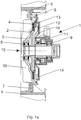
- Fig. 1a shows a fluid friction clutch according to the invention in a cross-sectional view.
- a drive body 2 is rotatably disposed, on the outer regions of a profile 4 is attached. This profile engages in a correspondingly offset profile of the output body 3, which is rotatably mounted on the shaft by means of the bearing 9.
- the drive body 2 also has a flow path 13, which extends radially from the reservoir 12 in the direction of the radial termination of the output body 3 and is in fluid communication with the coupling region between the profiles of the drive body 2 and the output body 3. According to the embodiment shown here, this flow path serves to supply the viscous fluid into the coupling region. Adjacent to the flow path 13 is located in the storage space 12, in which inter alia, a rocker arm 10 is received, which opens or closes the opening of the flow path 13 in dependence of its parking position.
- an actuator 11 which has a coil according to the embodiment shown here, which can build up a magnetic field via electrical lines.
- a ring 6 is connected via a fastening screw 8, which represents a fastening device for the fan blades 5.
- the plastic sheath 7 is reduced such that the fastening ring 6 largely flat on the output body 3 up or rests and can be connected by means of fastening screws 8 with the output body 3.
- the plastic sheath consists of the same material from which the fan blades 5 are made.
- a fastening screw In the Fig. 1 a is shown a fastening screw, wherein it is within the meaning of the present invention to use a plurality of fastening screws.
- the reservoir 12 should be designed with the largest possible diameter so that the centrifugal force-dependent back pressure of the return pump remains as low as possible.
- This large diameter of the storage space 12 can be achieved for example by the one-sided waiver of the drive body profiling (4). Furthermore, this results in the possibility that can be resorted to a forming technology cheaper producible rear housing cover 14.
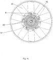
- Fig. 1b and 1c show the drive Fig. 1a with an impeller in a cross section and top view.
- the fan ring 37, the fan screw 36, the fasteners 8 and the cooling fins of the fan hub 35 is shown. Furthermore, the partially plastic-coated fastening device 6 can be seen, which is a fixing ring with predetermined recesses according to the embodiment shown here.
- the reference numeral 15, the axis of rotation or shaft of the drive is marked.
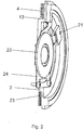
- Fig. 2 shows a sectional perspective view of the drive body 2 with a control device Fig. 1 a.
- the flow path 13 the return opening 20 of another flow path, the storage space 23 and the valve lever 24 can be seen.
- a magnet armature 22 is provided which serves in particular for transmitting the actuating force from the actuator to the valve lever.
- the return bore 20 so far be extended to the inside, that the mouth above the liquid level in the reservoir 23 is located. This is particularly important when very high drive speeds are required, since in these cases the pressure on the fluid can dominate the starting pressure of the pump due to the centrifugal force in the return flow bore 21. This can lead to the clutch partially being switched on unintentionally.
- the aim is to provide the largest possible diameter of the front side.
- the front side housing half of the fluid friction clutch can be effectively equipped with cooling fins.
- the screwed area of the fan hub is set to a relatively large diameter, the plastic casing being cut out at least for the fastening screws and their passage openings in the connecting area.
- the larger diameter of the screw leads to a reduction of the mechanical stresses, due to the larger lever arm of the force introduction at the mounting area of the fan.
- Fig. 3 shows an alternative embodiment of a fluid friction clutch according to the invention in cross section, in which in particular a front access from the central screw 34 is provided.
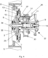
- Fig. 4 shows an alternative embodiment of a fluid friction clutch according to the invention in combination with a water pump or parts hereof.
- the centrally bolted coupling is mounted on a water pump in such a way that the shaft 15 are rotatably connected by means of the central attachment 34 both for the water pump and for the fluid friction clutch.
- the drive according to this alternative embodiment via pulley 30 which is rotatably connected to the shaft 15.
- the actuator 11 for the actuation of the rocker arm 10 is according to this embodiment does not have a ball bearing of the rotating shaft, but is mounted on the housing of the water pump 32.
- the magnetic flux is conducted via the steel hub of the pulley 30 to the armature 37 and causes the change in position of the rocker arm 10 when current flows through the actuator 11 via the control lines 36.
- the magnetic reflux takes place via the inserted into the pulley steel sleeve 31, wherein according to a particularly preferred Embodiment, the pulley in this case of a non-ferromagnetic, d. H. non-magnetically conductive material, such as aluminum or alloys thereof and / or the like is produced.
- Another advantage of this alternative embodiment is that the number of bearings required to operate the water pump and the fluid friction clutch can be reduced, so that, as in Fig. 4 shown, only two bearings 9 sufficient for fastening the components.
- Fig. 5 and 6 show further alternative embodiments of the fluid friction clutch according to the invention, in which compared to the previously described fluid friction clutches of the actuator is mounted on the front side of the clutch.
- Fig. 5 is a cross-sectional view of the outer housing of the actuator 11 and the control lines 36 can be seen. About the recesses in the center of rotation of the cooling fins 35, the actuator is in operative connection with the rocker arm 10 of the fluid friction clutch.
- the housing 14 closes off the fluid friction clutch toward the front, at least in a liquid-tight manner, wherein, according to the exemplary embodiment illustrated here, the drive body has a profiled section as a coupling region on both side surfaces, which engages in correspondingly designed profiles of the output body 27. It can be seen the flow path 13 and the reservoir 12 for the viscous fluid.
- the driven pulley 27 is further supported on the shaft 15 via the bearing 9.
- Fig. 6 shows a section of the fluid friction clutch Fig. 5 in which a perspective cut representation of the drive body including the actuator 11 and its connection means 36 is shown. Evident are the profiled portions of the drive body 28, wherein further the valve lever 24 is shown for opening and closing the flow paths and its arrangement with respect to the actuator.
Claims (20)
- Ventilateur comprenant un accouplement à friction de liquide, comprenant un arbre (15) monté en rotation, un corps menant (2) monté en étant solidaire en rotation sur l'arbre, un corps mené (3) monté en rotation sur l'arbre et une zone d'accouplement disposée entre le corps menant et le corps mené et recevant un fluide visqueux, où le ventilateur, en particulier ses ailettes de ventilateur (5) sont assemblées, au moyen d'un élément de fixation (6), avec la zone extérieure du corps mené (3), caractérisé en ce que l'élément de fixation est au moins partiellement gainé de matière plastique, où le diamètre de vissage de l'élément de fixation servant de moyeu de ventilateur est disposé à l'extérieur du corps menant (2) dans le sens radial où, dans la zone d'assemblage de l'élément de fixation, le gainage en matière plastique est évidé au moins pour les vis d'assemblage et pour leurs ouvertures de passage.
- Ventilateur selon la revendication 1, caractérisé en ce que l'élément de fixation est au moins un segment annulaire et / ou un anneau structuré et / ou un anneau comportant des évidements prédéfinis.
- Ventilateur selon au moins l'une des revendications précédentes, caractérisé en ce qu'au moins un premier et au moins un deuxième trajet d'écoulement sont prévus, trajets d'écoulement qui relient un espace de réserve de fluide (12), à la zone d'accouplement, et il est prévu au moins un dispositif réglable (10) pour les trajets d'écoulement, dispositif à l'aide duquel les trajets d'écoulement sont ouverts et fermés.
- Ventilateur selon au moins l'une quelconque des revendications précédentes, caractérisé en ce qu'au moins un trajet d'écoulement s'étend aussi loin à l'intérieur du corps menant, suivant la direction radiale, que le trajet d'écoulement débouche au-dessus du niveau du fluide contenu dans l'espace de réserve de fluide (12).
- Ventilateur selon au moins l'une quelconque des revendications précédentes, caractérisé en ce que le moyeu du ventilateur est formé par l'anneau de fixation (6) au moins partiellement gainé de matière plastique.
- Ventilateur selon au moins l'une quelconque des revendications précédentes, caractérisé en ce que l'anneau de fixation présente des ouvertures qui sont disposées sur un rayon prédéfini par rapport à l'axe de rotation.
- Ventilateur selon au moins la revendication 5, caractérisé en ce qu'il n'est prévu aucun gainage de matière plastique (7) dans les ouvertures et dans une zone prédéfinie tout autour de l'ouverture.
- Ventilateur selon au moins l'une quelconque des revendications précédentes, caractérisé en ce que l'accouplement à friction de liquide présente un assemblage central (34) accessible par le côté frontal.
- Ventilateur selon au moins l'une quelconque des revendications précédentes, caractérisé en ce que l'anneau de fixation (6) est assemblé avec le corps mené (3) par un type d'assemblage qui est choisi parmi un groupe de types d'assemblages qui présente des assemblages réalisés par action de force, par complémentarité de forme et / ou par continuité de matière, comme par exemple des assemblages vissés, des assemblages rivés, des assemblages collés, des assemblages brasés, des assemblages soudés, des combinaisons de ces types d'assemblages et autres assemblages analogues.
- Ventilateur selon au moins l'une quelconque des revendications précédentes, caractérisé en ce que des lamelles, en particulier des lamelles de refroidissement (35), sont disposées sur le côté du corps mené, tourné vers l'avant.
- Ventilateur selon au moins l'une quelconque des revendications précédentes, caractérisé en ce que l'accouplement est disposé dans un prolongement axial d'un dispositif d'entraînement, en particulier d'une pompe à eau d'un véhicule automobile.
- Ventilateur selon au moins la revendication 11, caractérisé en ce que le support de l'accouplement, mobile en rotation, est réalisé au moyen d'un palier côté sortie (9) de l'accouplement à friction de liquide et au moyen d'un palier du dispositif d'entraînement.
- Ventilateur selon au moins l'une quelconque des revendications précédentes, caractérisé en ce que le dispositif réglable (10) pour les trajets d'écoulement est en particulier au moins un levier à bascule réglable qui est modifié, dans sa position de réglage, de préférence au moyen d'un actionneur électromagnétique (11).
- Ventilateur selon au moins la revendication 13, caractérisé en ce que l'actionneur électromagnétique (11) présente des bobines magnétiques qui sont disposées dans la zone des paliers de l'axe rotatif et / ou directement dans la zone du carter du dispositif d'entraînement.
- Ventilateur selon au moins l'une quelconque des revendications précédentes, caractérisé en ce que le flux magnétique de l'actionneur électromagnétique passe au moins par un moyeu ferromagnétique et / ou par un axe de l'accouplement.
- Ventilateur selon au moins l'une quelconque des revendications précédentes, caractérisé en ce que le flux magnétique passe par un composant ferromagnétique qui est de préférence un manchon (31) en matériau ferromagnétique, ledit manchon étant inséré dans une poulie à courroie réalisée de manière non ferromagnétique.
- Ventilateur selon au moins la revendication 13, caractérisé en ce que l'actionneur électromagnétique (11) est disposé sur le côté frontal de l'accouplement.
- Ventilateur selon au moins l'une quelconque des revendications précédentes, caractérisé en ce que la zone d'accouplement servant à la transmission d'un couple est formée à chaque fois sur au moins un côté du corps menant (2) et du corps mené (3), essentiellement par des structures profilées (4) concentriques et s'engrenant les unes dans les autres.
- Dispositif d'actionnement d'un système de ventilation pour un véhicule automobile qui présente au moins un ensemble d'entraînement, un élément d'assemblage et au moins un ventilateur selon au moins l'une quelconque des revendications précédentes.
- Utilisation d'un ventilateur selon au moins l'une quelconque des revendications précédentes, servant à l'actionnement d'un système de ventilation prévu pour un véhicule automobile.
Applications Claiming Priority (2)
| Application Number | Priority Date | Filing Date | Title |
|---|---|---|---|
| DE102004008861A DE102004008861A1 (de) | 2004-02-20 | 2004-02-20 | Flüssigkeitsreibkupplung für einen Kraftfahrzeuglüfter |
| DE102004008861 | 2004-02-20 |
Publications (3)
| Publication Number | Publication Date |
|---|---|
| EP1566547A2 EP1566547A2 (fr) | 2005-08-24 |
| EP1566547A3 EP1566547A3 (fr) | 2012-06-13 |
| EP1566547B1 true EP1566547B1 (fr) | 2016-12-14 |
Family
ID=34706901
Family Applications (1)
| Application Number | Title | Priority Date | Filing Date |
|---|---|---|---|
| EP05002685.5A Active EP1566547B1 (fr) | 2004-02-20 | 2005-02-09 | Accouplement à fluide pour ventilateur d' un véhicule |
Country Status (3)
| Country | Link |
|---|---|
| US (1) | US7246691B2 (fr) |
| EP (1) | EP1566547B1 (fr) |
| DE (1) | DE102004008861A1 (fr) |
Families Citing this family (12)
| Publication number | Priority date | Publication date | Assignee | Title |
|---|---|---|---|---|
| MX2008001205A (es) * | 2005-07-29 | 2008-03-19 | Horton Inc | Embrague viscoso accionado electromagneticamente. |
| DE102006008576A1 (de) * | 2006-02-22 | 2007-08-30 | Behr Gmbh & Co. Kg | Lüfterantriebsvorrichtung |
| US9534651B2 (en) * | 2007-07-20 | 2017-01-03 | GM Global Technology Operations LLC | Method of manufacturing a damped part |
| DE102007056493B3 (de) * | 2007-11-22 | 2009-06-04 | Voith Patent Gmbh | Lüfterrad |
| DE102007056492B3 (de) * | 2007-11-22 | 2009-06-04 | Voith Patent Gmbh | Lüfterrad |
| US20120063879A1 (en) * | 2009-07-21 | 2012-03-15 | Veilleux Jr Leo J | Energy efficient ips blower assembly |
| BR112012011837A2 (pt) | 2009-11-17 | 2018-09-11 | Horton Inc | embreagem viscosa integrada |
| US20140023526A1 (en) * | 2011-04-13 | 2014-01-23 | Borgwarner Inc. | Hybrid coolant pump |
| EP3636948B1 (fr) | 2013-03-14 | 2022-05-04 | Horton, Inc. | Embrayage visqueux et configuration de réservoir associée |
| CN103244431A (zh) * | 2013-04-19 | 2013-08-14 | 界首市鑫洋机电有限公司 | 一种多用可调节大功率自吸式喷射泵 |
| DE102013222116A1 (de) | 2013-10-30 | 2015-04-30 | MAHLE Behr GmbH & Co. KG | Lüfterkupplung |
| KR102424078B1 (ko) | 2017-02-01 | 2022-07-22 | 호르톤 인코포레이티드 | 전자기 코일 연결 조립체 및 관련 방법 |
Family Cites Families (20)
| Publication number | Priority date | Publication date | Assignee | Title |
|---|---|---|---|---|
| DE1158769B (de) * | 1956-05-02 | 1963-12-05 | Schwitzer Corp | Fluessigkeitskupplung |
| US3749214A (en) * | 1971-11-26 | 1973-07-31 | Eaton Corp | Viscous coupling having an improved coolant system |
| GB1401069A (en) | 1972-12-12 | 1975-07-16 | Chrysler Uk | Cooling fan assemblies |
| US3893555A (en) * | 1973-05-24 | 1975-07-08 | Dynair Ltd | Rotary fans |
| DE7321965U (de) * | 1973-06-13 | 1976-08-12 | Alumetall Gmbh, 8500 Nuernberg | Luefterrad fuer ventilatoren |
| DE3041793C2 (de) * | 1980-11-06 | 1984-08-02 | Süddeutsche Kühlerfabrik Julius Fr. Behr GmbH & Co KG, 7000 Stuttgart | Flüssigkeitsreibungskupplung |
| US4633994A (en) * | 1983-06-20 | 1987-01-06 | Eaton Corporation | Viscous fan drive and axially movable valve element |
| GB2163835B (en) * | 1984-08-30 | 1988-03-30 | Aisin Seiki | Viscous fluid couplings |
| JPH07103904B2 (ja) * | 1986-11-21 | 1995-11-08 | 臼井国際産業株式会社 | 温度感応型流体式フアン・カツプリング装置 |
| DE3823871A1 (de) * | 1988-07-14 | 1990-01-18 | Sueddeutsche Kuehler Behr | Fluessigkeitsreibungskupplung, insbesondere fuer den antrieb eines luefters zur kuehlung von kraftfahrzeugmotoren |
| DE8908359U1 (fr) * | 1989-07-08 | 1989-10-26 | Sueddeutsche Kuehlerfabrik Julius Fr. Behr Gmbh & Co Kg, 7000 Stuttgart, De | |
| US5152384A (en) * | 1991-10-31 | 1992-10-06 | Eaton Corporation | Viscous fluid coupling and remote control assembly therefor |
| US5330040A (en) * | 1992-10-05 | 1994-07-19 | General Motors Corporation | Ringed cover and seal for a viscous fluid clutch and method of making |
| US5358382A (en) * | 1993-07-21 | 1994-10-25 | Eaton Corporation | Fan and fan drive assembly |
| DE19710608B4 (de) * | 1997-03-14 | 2007-10-31 | Behr Gmbh & Co. Kg | Axiallüfter für den Kühler eines Verbrennungsmotors |
| DE19742823B4 (de) * | 1997-09-27 | 2004-05-19 | Behr Gmbh & Co. | Flüssigkeitsreibungskupplung |
| US6056098A (en) * | 1998-02-04 | 2000-05-02 | Borg-Warner Automotive, Inc. | Viscous fluid coupling and improved valve assembly therefor |
| US6206639B1 (en) * | 1999-02-25 | 2001-03-27 | Borgwarner Inc. | Enhanced fan and fan drive assembly |
| DE19925132B4 (de) * | 1999-06-02 | 2016-08-04 | Mahle International Gmbh | Flüssigkeitsreibungskupplung |
| ES2253618T3 (es) * | 2002-08-23 | 2006-06-01 | BEHR GMBH & CO. KG | Embrague de friccion viscosa. |
-
2004
- 2004-02-20 DE DE102004008861A patent/DE102004008861A1/de not_active Withdrawn
-
2005
- 2005-02-09 EP EP05002685.5A patent/EP1566547B1/fr active Active
- 2005-02-18 US US11/061,685 patent/US7246691B2/en active Active
Non-Patent Citations (1)
| Title |
|---|
| None * |
Also Published As
| Publication number | Publication date |
|---|---|
| US7246691B2 (en) | 2007-07-24 |
| DE102004008861A1 (de) | 2005-09-08 |
| EP1566547A3 (fr) | 2012-06-13 |
| EP1566547A2 (fr) | 2005-08-24 |
| US20050189194A1 (en) | 2005-09-01 |
Similar Documents
| Publication | Publication Date | Title |
|---|---|---|
| EP1566547B1 (fr) | Accouplement à fluide pour ventilateur d' un véhicule | |
| EP0687584B1 (fr) | Installation de chauffage pour véhicules | |
| EP1476645B1 (fr) | Pompe electrique de fluide refrigerant a soupape integree et procede de commande de ladite soupape | |
| EP2092222B1 (fr) | Vanne de commande de débits volumétriques | |
| EP1391624B1 (fr) | Embrayage à frottement visqueux | |
| EP1731787B1 (fr) | Accouplement à fluide visqueux | |
| DE10232138A1 (de) | Vorrichtung zum Antrieb einer Kühlmittelpumpe | |
| DE112008002669T5 (de) | Elektronisch gesteuerte Fluidkopplungsvorrichtung mit Fluidrücklaufsteuerung | |
| DE19901123A1 (de) | Regelbare Radialpumpe, insbesondere zum Fördern eines Kühlmittels für ein Kraftfahrzeug | |
| DE112008002668T5 (de) | Elektronisch gesteuerte Fluidkopplungsvorrichtung mit Fluidrücklaufsteuerung und verbesserter Kühlung | |
| DE112008002654T5 (de) | Elektronisch gesteuerte Fluidkopplungsvorrichtung mit Fluidrücklaufsteuerung und verbesserter Kühlung | |
| DE112008002652T5 (de) | Elektronisch gesteuerte Fluidkopplungsvorrichtung mit Fluidrücklaufsteuerung und Rückschlagfventil | |
| DE112009001025T5 (de) | Elektronisch gesteuerter Viskolüfterantrieb mit Buchse | |
| EP1989416A1 (fr) | Dispositif d'entrainement de ventilateur | |
| DE102010037391A1 (de) | Wasserpumpe für ein Fahrzeug | |
| EP2262989B1 (fr) | Embrayage à friction et système d entraînement pour le refroidissement d un moteur à combustion d un véhicule équipé d un embrayage à friction | |
| EP1945955B1 (fr) | Pompe a fluide | |
| DE4442451A1 (de) | Flüssigkeitsreibungskupplung | |
| DE102013113362B4 (de) | Regelbare Pumpe für eine Verbrennungskraftmaschine | |
| DE102012216337A1 (de) | Primärbaugruppe für eine Flüssigkeitsreibungskupplung, Flüssigkeitsreibungskupplung, Verfahren und Steuergerät zum Ansteuern einer Flüssigkeitsreibungskupplung | |
| WO2006005328A1 (fr) | Module huile avec pompe a eau et echangeur de chaleur | |
| DE102009014027A1 (de) | Vorrichtung zur Übertragung eines Drehmomentes von einem Verbrennungsmotor zu einem Nebenaggregat | |
| DE10318711A1 (de) | Vorrichtung zum Antrieb der Kühlmittelpumpe einer Brennkraftmaschine | |
| EP2058269B1 (fr) | Chariot de manutention doté d'un moteur à combustion et d'une unité électrique | |
| EP1541887B1 (fr) | Dispositif de réfrigération des lamelles de friction d'un embrayage |
Legal Events
| Date | Code | Title | Description |
|---|---|---|---|
| PUAI | Public reference made under article 153(3) epc to a published international application that has entered the european phase |
Free format text: ORIGINAL CODE: 0009012 |
|
| AK | Designated contracting states |
Kind code of ref document: A2 Designated state(s): AT BE BG CH CY CZ DE DK EE ES FI FR GB GR HU IE IS IT LI LT LU MC NL PL PT RO SE SI SK TR |
|
| AX | Request for extension of the european patent |
Extension state: AL BA HR LV MK YU |
|
| PUAL | Search report despatched |
Free format text: ORIGINAL CODE: 0009013 |
|
| AK | Designated contracting states |
Kind code of ref document: A3 Designated state(s): AT BE BG CH CY CZ DE DK EE ES FI FR GB GR HU IE IS IT LI LT LU MC NL PL PT RO SE SI SK TR |
|
| AX | Request for extension of the european patent |
Extension state: AL BA HR LV MK YU |
|
| RIC1 | Information provided on ipc code assigned before grant |
Ipc: F04D 25/02 20060101AFI20120508BHEP |
|
| 17P | Request for examination filed |
Effective date: 20121213 |
|
| AKX | Designation fees paid |
Designated state(s): AT BE BG CH CY CZ DE DK EE ES FI FR GB GR HU IE IS IT LI LT LU MC NL PL PT RO SE SI SK TR |
|
| 17Q | First examination report despatched |
Effective date: 20130219 |
|
| RAP1 | Party data changed (applicant data changed or rights of an application transferred) |
Owner name: MAHLE BEHR GMBH & CO. KG |
|
| GRAP | Despatch of communication of intention to grant a patent |
Free format text: ORIGINAL CODE: EPIDOSNIGR1 |
|
| INTG | Intention to grant announced |
Effective date: 20160524 |
|
| GRAJ | Information related to disapproval of communication of intention to grant by the applicant or resumption of examination proceedings by the epo deleted |
Free format text: ORIGINAL CODE: EPIDOSDIGR1 |
|
| GRAP | Despatch of communication of intention to grant a patent |
Free format text: ORIGINAL CODE: EPIDOSNIGR1 |
|
| INTC | Intention to grant announced (deleted) | ||
| GRAS | Grant fee paid |
Free format text: ORIGINAL CODE: EPIDOSNIGR3 |
|
| GRAA | (expected) grant |
Free format text: ORIGINAL CODE: 0009210 |
|
| INTG | Intention to grant announced |
Effective date: 20161021 |
|
| RIN1 | Information on inventor provided before grant (corrected) |
Inventor name: STOKLOSSA, RUDOLF Inventor name: SCHULTHEISS, GEROLD, DIPL.-ING. Inventor name: LINDAUER, KUNO |
|
| AK | Designated contracting states |
Kind code of ref document: B1 Designated state(s): AT BE BG CH CY CZ DE DK EE ES FI FR GB GR HU IE IS IT LI LT LU MC NL PL PT RO SE SI SK TR |
|
| REG | Reference to a national code |
Ref country code: GB Ref legal event code: FG4D Free format text: NOT ENGLISH |
|
| REG | Reference to a national code |
Ref country code: CH Ref legal event code: EP |
|
| REG | Reference to a national code |
Ref country code: IE Ref legal event code: FG4D Free format text: LANGUAGE OF EP DOCUMENT: GERMAN |
|
| REG | Reference to a national code |
Ref country code: AT Ref legal event code: REF Ref document number: 853854 Country of ref document: AT Kind code of ref document: T Effective date: 20170115 |
|
| REG | Reference to a national code |
Ref country code: DE Ref legal event code: R096 Ref document number: 502005015450 Country of ref document: DE |
|
| REG | Reference to a national code |
Ref country code: FR Ref legal event code: PLFP Year of fee payment: 13 |
|
| REG | Reference to a national code |
Ref country code: LT Ref legal event code: MG4D |
|
| REG | Reference to a national code |
Ref country code: NL Ref legal event code: MP Effective date: 20161214 |
|
| PG25 | Lapsed in a contracting state [announced via postgrant information from national office to epo] |
Ref country code: LT Free format text: LAPSE BECAUSE OF FAILURE TO SUBMIT A TRANSLATION OF THE DESCRIPTION OR TO PAY THE FEE WITHIN THE PRESCRIBED TIME-LIMIT Effective date: 20161214 Ref country code: SE Free format text: LAPSE BECAUSE OF FAILURE TO SUBMIT A TRANSLATION OF THE DESCRIPTION OR TO PAY THE FEE WITHIN THE PRESCRIBED TIME-LIMIT Effective date: 20161214 Ref country code: GR Free format text: LAPSE BECAUSE OF FAILURE TO SUBMIT A TRANSLATION OF THE DESCRIPTION OR TO PAY THE FEE WITHIN THE PRESCRIBED TIME-LIMIT Effective date: 20170315 |
|
| PG25 | Lapsed in a contracting state [announced via postgrant information from national office to epo] |
Ref country code: FI Free format text: LAPSE BECAUSE OF FAILURE TO SUBMIT A TRANSLATION OF THE DESCRIPTION OR TO PAY THE FEE WITHIN THE PRESCRIBED TIME-LIMIT Effective date: 20161214 Ref country code: BE Free format text: LAPSE BECAUSE OF NON-PAYMENT OF DUE FEES Effective date: 20170228 |
|
| PG25 | Lapsed in a contracting state [announced via postgrant information from national office to epo] |
Ref country code: NL Free format text: LAPSE BECAUSE OF FAILURE TO SUBMIT A TRANSLATION OF THE DESCRIPTION OR TO PAY THE FEE WITHIN THE PRESCRIBED TIME-LIMIT Effective date: 20161214 |
|
| PG25 | Lapsed in a contracting state [announced via postgrant information from national office to epo] |
Ref country code: SK Free format text: LAPSE BECAUSE OF FAILURE TO SUBMIT A TRANSLATION OF THE DESCRIPTION OR TO PAY THE FEE WITHIN THE PRESCRIBED TIME-LIMIT Effective date: 20161214 Ref country code: CZ Free format text: LAPSE BECAUSE OF FAILURE TO SUBMIT A TRANSLATION OF THE DESCRIPTION OR TO PAY THE FEE WITHIN THE PRESCRIBED TIME-LIMIT Effective date: 20161214 Ref country code: EE Free format text: LAPSE BECAUSE OF FAILURE TO SUBMIT A TRANSLATION OF THE DESCRIPTION OR TO PAY THE FEE WITHIN THE PRESCRIBED TIME-LIMIT Effective date: 20161214 Ref country code: IS Free format text: LAPSE BECAUSE OF FAILURE TO SUBMIT A TRANSLATION OF THE DESCRIPTION OR TO PAY THE FEE WITHIN THE PRESCRIBED TIME-LIMIT Effective date: 20170414 Ref country code: RO Free format text: LAPSE BECAUSE OF FAILURE TO SUBMIT A TRANSLATION OF THE DESCRIPTION OR TO PAY THE FEE WITHIN THE PRESCRIBED TIME-LIMIT Effective date: 20161214 |
|
| PG25 | Lapsed in a contracting state [announced via postgrant information from national office to epo] |
Ref country code: PL Free format text: LAPSE BECAUSE OF FAILURE TO SUBMIT A TRANSLATION OF THE DESCRIPTION OR TO PAY THE FEE WITHIN THE PRESCRIBED TIME-LIMIT Effective date: 20161214 Ref country code: IT Free format text: LAPSE BECAUSE OF FAILURE TO SUBMIT A TRANSLATION OF THE DESCRIPTION OR TO PAY THE FEE WITHIN THE PRESCRIBED TIME-LIMIT Effective date: 20161214 Ref country code: PT Free format text: LAPSE BECAUSE OF FAILURE TO SUBMIT A TRANSLATION OF THE DESCRIPTION OR TO PAY THE FEE WITHIN THE PRESCRIBED TIME-LIMIT Effective date: 20170414 Ref country code: ES Free format text: LAPSE BECAUSE OF FAILURE TO SUBMIT A TRANSLATION OF THE DESCRIPTION OR TO PAY THE FEE WITHIN THE PRESCRIBED TIME-LIMIT Effective date: 20161214 Ref country code: BG Free format text: LAPSE BECAUSE OF FAILURE TO SUBMIT A TRANSLATION OF THE DESCRIPTION OR TO PAY THE FEE WITHIN THE PRESCRIBED TIME-LIMIT Effective date: 20170314 |
|
| REG | Reference to a national code |
Ref country code: DE Ref legal event code: R097 Ref document number: 502005015450 Country of ref document: DE |
|
| PG25 | Lapsed in a contracting state [announced via postgrant information from national office to epo] |
Ref country code: MC Free format text: LAPSE BECAUSE OF FAILURE TO SUBMIT A TRANSLATION OF THE DESCRIPTION OR TO PAY THE FEE WITHIN THE PRESCRIBED TIME-LIMIT Effective date: 20161214 |
|
| REG | Reference to a national code |
Ref country code: CH Ref legal event code: PL |
|
| PLBE | No opposition filed within time limit |
Free format text: ORIGINAL CODE: 0009261 |
|
| STAA | Information on the status of an ep patent application or granted ep patent |
Free format text: STATUS: NO OPPOSITION FILED WITHIN TIME LIMIT |
|
| PG25 | Lapsed in a contracting state [announced via postgrant information from national office to epo] |
Ref country code: LI Free format text: LAPSE BECAUSE OF NON-PAYMENT OF DUE FEES Effective date: 20170228 Ref country code: CH Free format text: LAPSE BECAUSE OF NON-PAYMENT OF DUE FEES Effective date: 20170228 |
|
| 26N | No opposition filed |
Effective date: 20170915 |
|
| GBPC | Gb: european patent ceased through non-payment of renewal fee |
Effective date: 20170314 |
|
| REG | Reference to a national code |
Ref country code: IE Ref legal event code: MM4A |
|
| PG25 | Lapsed in a contracting state [announced via postgrant information from national office to epo] |
Ref country code: DK Free format text: LAPSE BECAUSE OF FAILURE TO SUBMIT A TRANSLATION OF THE DESCRIPTION OR TO PAY THE FEE WITHIN THE PRESCRIBED TIME-LIMIT Effective date: 20161214 |
|
| PG25 | Lapsed in a contracting state [announced via postgrant information from national office to epo] |
Ref country code: LU Free format text: LAPSE BECAUSE OF NON-PAYMENT OF DUE FEES Effective date: 20170209 |
|
| REG | Reference to a national code |
Ref country code: BE Ref legal event code: MM Effective date: 20170228 |
|
| REG | Reference to a national code |
Ref country code: FR Ref legal event code: PLFP Year of fee payment: 14 |
|
| PG25 | Lapsed in a contracting state [announced via postgrant information from national office to epo] |
Ref country code: GB Free format text: LAPSE BECAUSE OF NON-PAYMENT OF DUE FEES Effective date: 20170314 Ref country code: SI Free format text: LAPSE BECAUSE OF FAILURE TO SUBMIT A TRANSLATION OF THE DESCRIPTION OR TO PAY THE FEE WITHIN THE PRESCRIBED TIME-LIMIT Effective date: 20161214 Ref country code: IE Free format text: LAPSE BECAUSE OF NON-PAYMENT OF DUE FEES Effective date: 20170209 |
|
| REG | Reference to a national code |
Ref country code: AT Ref legal event code: MM01 Ref document number: 853854 Country of ref document: AT Kind code of ref document: T Effective date: 20170209 |
|
| PG25 | Lapsed in a contracting state [announced via postgrant information from national office to epo] |
Ref country code: AT Free format text: LAPSE BECAUSE OF NON-PAYMENT OF DUE FEES Effective date: 20170209 |
|
| PG25 | Lapsed in a contracting state [announced via postgrant information from national office to epo] |
Ref country code: HU Free format text: LAPSE BECAUSE OF FAILURE TO SUBMIT A TRANSLATION OF THE DESCRIPTION OR TO PAY THE FEE WITHIN THE PRESCRIBED TIME-LIMIT; INVALID AB INITIO Effective date: 20050209 |
|
| PG25 | Lapsed in a contracting state [announced via postgrant information from national office to epo] |
Ref country code: CY Free format text: LAPSE BECAUSE OF NON-PAYMENT OF DUE FEES Effective date: 20161214 |
|
| PG25 | Lapsed in a contracting state [announced via postgrant information from national office to epo] |
Ref country code: TR Free format text: LAPSE BECAUSE OF FAILURE TO SUBMIT A TRANSLATION OF THE DESCRIPTION OR TO PAY THE FEE WITHIN THE PRESCRIBED TIME-LIMIT Effective date: 20161214 |
|
| PGFP | Annual fee paid to national office [announced via postgrant information from national office to epo] |
Ref country code: DE Payment date: 20200421 Year of fee payment: 16 |
|
| REG | Reference to a national code |
Ref country code: DE Ref legal event code: R119 Ref document number: 502005015450 Country of ref document: DE |
|
| PG25 | Lapsed in a contracting state [announced via postgrant information from national office to epo] |
Ref country code: DE Free format text: LAPSE BECAUSE OF NON-PAYMENT OF DUE FEES Effective date: 20210901 |
|
| PGFP | Annual fee paid to national office [announced via postgrant information from national office to epo] |
Ref country code: FR Payment date: 20230217 Year of fee payment: 19 |