EP1566547B1 - Fluid coupling for vehicle fan - Google Patents
Fluid coupling for vehicle fan Download PDFInfo
- Publication number
- EP1566547B1 EP1566547B1 EP05002685.5A EP05002685A EP1566547B1 EP 1566547 B1 EP1566547 B1 EP 1566547B1 EP 05002685 A EP05002685 A EP 05002685A EP 1566547 B1 EP1566547 B1 EP 1566547B1
- Authority
- EP
- European Patent Office
- Prior art keywords
- fan according
- fan
- drive
- clutch
- fluid
- Prior art date
- Legal status (The legal status is an assumption and is not a legal conclusion. Google has not performed a legal analysis and makes no representation as to the accuracy of the status listed.)
- Active
Links
Images


Classifications
-
- F—MECHANICAL ENGINEERING; LIGHTING; HEATING; WEAPONS; BLASTING
- F04—POSITIVE - DISPLACEMENT MACHINES FOR LIQUIDS; PUMPS FOR LIQUIDS OR ELASTIC FLUIDS
- F04D—NON-POSITIVE-DISPLACEMENT PUMPS
- F04D25/00—Pumping installations or systems
- F04D25/02—Units comprising pumps and their driving means
- F04D25/022—Units comprising pumps and their driving means comprising a yielding coupling, e.g. hydraulic
Definitions
- the present invention relates to a fan with a fluid friction clutch for a motor vehicle ventilator.
- Such fluid friction clutches are known in the art and are used for radiator fans or as drives for such to allow sufficient heat dissipation of the thermal energy generated by, for example, a fuel engine.
- Such fan clutches are particularly used for medium power vehicles such as vans, off-road vehicles, light trucks and agricultural applications.
- bimetallic driven clutches which have only secondary storage rooms, especially when using liquid friction clutches.
- this embodiment has control problems at low speed and a rapid connection of the clutch or its start-up characteristic. This is especially true for vehicles with gasoline rotors disadvantageous in which the ratio between rated speed and idle speed of the rotor assumes relatively large values.
- the object of the present invention is to improve the fan coupling known in the prior art and in particular to enable a more cost-effective production of such a coupling.
- the vehicle fan according to the invention has at least one rotatably mounted shaft on which at least one rotationally fixed drive body and at least one rotatably mounted output body is arranged. Between the drive and driven body, a coupling region is provided, which receives a viscous fluid and thereby is able to transmit a torque between the drive body and the output body.
- the fan is characterized in that the fan, in particular the fan blades of the fan are connected by means of a fastening element with the outer region of the driven body, wherein the fastening element is at least partially plastic coated, wherein the screwing diameter of the fastening element is arranged as a fan hub radially outside of the drive body, said in the connecting region of the fastening element, the plastic casing is recessed at least for the connecting screws and their passage openings.
- a drive body of the fan according to the invention are understood according to the present invention at least partially profiled discs, which are rotatably or non-rotatably mounted on a shaft and are used to transmit a predetermined torque.
- the output body are also at least partially profiled discs understood that cooperate with at least one drive body in the way that directly or indirectly, a predetermined torque is transmitted from the drive body to the output body.
- a metal ring is understood, which is connected to at least one predetermined area of the driven body and is arranged in a predetermined area on the fans or in the region of the fan blades.
- the attachment ring is preferably made of metallic materials but may also be made of a plastic or composite material such as plastic, carbon fiber composites and the like according to a particularly preferred embodiment.
- the fluid friction clutch has at least one first and at least one second flow path, which connect at least one fluid reservoir to at least one coupling region. Furthermore, at least one controllable device is provided with which at least one flow path, but in particular the flow paths are opened and closed.
- At least one flow path extends in the radial direction as far as within the Drive body that the mouth of the flow path above the fluid level opens in the fluid reservoir of the fluid friction clutch.
- the hub of the fan is formed by the at least partially plastic-coated mounting ring.
- a plastic casing according to the present invention is understood to mean a coating selected from a group of materials comprising paints, natural or synthetic plastics, resins, combinations thereof, and the like.
- the fastening ring has openings which are arranged at a predetermined radius with respect to the axis of rotation. According to a further particularly preferred embodiment, these openings have no plastic coating in a predetermined area and in the openings themselves, wherein it is not precluded to apply a corrosion protection layer in these areas.
- the fluid friction clutch has a central connection accessible from the front side.
- the side of the fluid friction clutch for example, by the air flow of the fan or streamed through the wind of a motor vehicle, in particular is flowed frontal.
- This can be, for example, the front that belongs to. a radiator of the vehicle is aligned.
- fins in particular cooling fins, are arranged on the side of the output body facing the front. These extend according to a particularly preferred embodiment of the radially outer regions of the drive body radially inwardly, wherein in particular in the embodiment with a central connection of the region of the central connection itself is recessed. The same applies to the areas of the fastening ring, with which it is connected to the output body.
- the fluid friction clutch is characterized in that the fastening ring is connected to the driven body by a connection type which is selected from a group of connection types, which force, form and / or material connections, such as Rautagenen, rivet joints, adhesive bonds , Soldering, welding, combinations thereof and the like.
- the fluid friction clutch is arranged in the axial extension of a drive device of a motor vehicle, such as a water pump of a motor vehicle.
- a drive device of a motor vehicle such as a water pump of a motor vehicle.
- This can be both a solid compound, as well as a detachable connection, as z. B. by a central connection which extends in the axial direction in the Rotationsvirelle.
- the support of the output body is carried out according to a further particularly preferred embodiment by means of a driven-side bearing of Fluid friction clutch and another bearing that is assigned to the drive device.
- the fluid friction clutch has controllable devices for the flow paths which, according to a particularly preferred embodiment, are controllable rocker arms, which can preferably be changed in their position by means of an electromagnetic actuator.
- the electromagnetic actuator has, for example, magnetic coils which, according to a particularly preferred embodiment, are arranged in the region of the bearings of the rotating axes and / or directly in the region of the housing of the drive device.
- the magnetic flux of the electromagnetic actuator is effected according to a particularly preferred embodiment, at least via a ferromagnetic hub and / or axis of the coupling, for example, of an adjacent component. Furthermore, the magnetic flux is effected via at least one ferromagnetic component, which is preferably a sleeve inserted in a non-ferromagnetic pulley, which itself is made of ferromagnetic material.
- the aim of this arrangement is to build a closed ring of the magnetic field, over which the controllable devices or the controllable device, such as a rocker arm, can be reliably controlled.
- the electromagnetic actuator can also be arranged on the front side of the coupling.
- the coupling region of the fluid friction clutch for transmitting a torque substantially on profile structures, which are arranged concentrically on at least one side of the output and drive body and engage with a predetermined distance.
- the invention also includes an apparatus for operating a ventilation system, in particular for a motor vehicle, which has at least one fan, a drive unit, a connecting element and at least one fluid friction clutch according to the present invention.
- a fluid friction clutch according to the invention for operating a ventilation system for a motor vehicle is also within the meaning of the present invention.
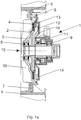
- Fig. 1a shows a fluid friction clutch according to the invention in a cross-sectional view.
- a drive body 2 is rotatably disposed, on the outer regions of a profile 4 is attached. This profile engages in a correspondingly offset profile of the output body 3, which is rotatably mounted on the shaft by means of the bearing 9.
- the drive body 2 also has a flow path 13, which extends radially from the reservoir 12 in the direction of the radial termination of the output body 3 and is in fluid communication with the coupling region between the profiles of the drive body 2 and the output body 3. According to the embodiment shown here, this flow path serves to supply the viscous fluid into the coupling region. Adjacent to the flow path 13 is located in the storage space 12, in which inter alia, a rocker arm 10 is received, which opens or closes the opening of the flow path 13 in dependence of its parking position.
- an actuator 11 which has a coil according to the embodiment shown here, which can build up a magnetic field via electrical lines.
- a ring 6 is connected via a fastening screw 8, which represents a fastening device for the fan blades 5.
- the plastic sheath 7 is reduced such that the fastening ring 6 largely flat on the output body 3 up or rests and can be connected by means of fastening screws 8 with the output body 3.
- the plastic sheath consists of the same material from which the fan blades 5 are made.
- a fastening screw In the Fig. 1 a is shown a fastening screw, wherein it is within the meaning of the present invention to use a plurality of fastening screws.
- the reservoir 12 should be designed with the largest possible diameter so that the centrifugal force-dependent back pressure of the return pump remains as low as possible.
- This large diameter of the storage space 12 can be achieved for example by the one-sided waiver of the drive body profiling (4). Furthermore, this results in the possibility that can be resorted to a forming technology cheaper producible rear housing cover 14.
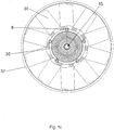
- Fig. 1b and 1c show the drive Fig. 1a with an impeller in a cross section and top view.
- the fan ring 37, the fan screw 36, the fasteners 8 and the cooling fins of the fan hub 35 is shown. Furthermore, the partially plastic-coated fastening device 6 can be seen, which is a fixing ring with predetermined recesses according to the embodiment shown here.
- the reference numeral 15, the axis of rotation or shaft of the drive is marked.
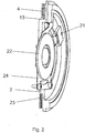
- Fig. 2 shows a sectional perspective view of the drive body 2 with a control device Fig. 1 a.
- the flow path 13 the return opening 20 of another flow path, the storage space 23 and the valve lever 24 can be seen.
- a magnet armature 22 is provided which serves in particular for transmitting the actuating force from the actuator to the valve lever.
- the return bore 20 so far be extended to the inside, that the mouth above the liquid level in the reservoir 23 is located. This is particularly important when very high drive speeds are required, since in these cases the pressure on the fluid can dominate the starting pressure of the pump due to the centrifugal force in the return flow bore 21. This can lead to the clutch partially being switched on unintentionally.
- the aim is to provide the largest possible diameter of the front side.
- the front side housing half of the fluid friction clutch can be effectively equipped with cooling fins.
- the screwed area of the fan hub is set to a relatively large diameter, the plastic casing being cut out at least for the fastening screws and their passage openings in the connecting area.
- the larger diameter of the screw leads to a reduction of the mechanical stresses, due to the larger lever arm of the force introduction at the mounting area of the fan.
- Fig. 3 shows an alternative embodiment of a fluid friction clutch according to the invention in cross section, in which in particular a front access from the central screw 34 is provided.
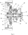
- Fig. 4 shows an alternative embodiment of a fluid friction clutch according to the invention in combination with a water pump or parts hereof.
- the centrally bolted coupling is mounted on a water pump in such a way that the shaft 15 are rotatably connected by means of the central attachment 34 both for the water pump and for the fluid friction clutch.
- the drive according to this alternative embodiment via pulley 30 which is rotatably connected to the shaft 15.
- the actuator 11 for the actuation of the rocker arm 10 is according to this embodiment does not have a ball bearing of the rotating shaft, but is mounted on the housing of the water pump 32.
- the magnetic flux is conducted via the steel hub of the pulley 30 to the armature 37 and causes the change in position of the rocker arm 10 when current flows through the actuator 11 via the control lines 36.
- the magnetic reflux takes place via the inserted into the pulley steel sleeve 31, wherein according to a particularly preferred Embodiment, the pulley in this case of a non-ferromagnetic, d. H. non-magnetically conductive material, such as aluminum or alloys thereof and / or the like is produced.
- Another advantage of this alternative embodiment is that the number of bearings required to operate the water pump and the fluid friction clutch can be reduced, so that, as in Fig. 4 shown, only two bearings 9 sufficient for fastening the components.
- Fig. 5 and 6 show further alternative embodiments of the fluid friction clutch according to the invention, in which compared to the previously described fluid friction clutches of the actuator is mounted on the front side of the clutch.
- Fig. 5 is a cross-sectional view of the outer housing of the actuator 11 and the control lines 36 can be seen. About the recesses in the center of rotation of the cooling fins 35, the actuator is in operative connection with the rocker arm 10 of the fluid friction clutch.
- the housing 14 closes off the fluid friction clutch toward the front, at least in a liquid-tight manner, wherein, according to the exemplary embodiment illustrated here, the drive body has a profiled section as a coupling region on both side surfaces, which engages in correspondingly designed profiles of the output body 27. It can be seen the flow path 13 and the reservoir 12 for the viscous fluid.
- the driven pulley 27 is further supported on the shaft 15 via the bearing 9.
- Fig. 6 shows a section of the fluid friction clutch Fig. 5 in which a perspective cut representation of the drive body including the actuator 11 and its connection means 36 is shown. Evident are the profiled portions of the drive body 28, wherein further the valve lever 24 is shown for opening and closing the flow paths and its arrangement with respect to the actuator.
Description
Die vorliegende Erfindung betrifft einen Lüfter mit einer Flüssigkeitsreibkupplung für einen Kraftfahrzeuglüfter.The present invention relates to a fan with a fluid friction clutch for a motor vehicle ventilator.
Solche Flüssigkeitsreibkupplungen sind im Stand der Technik bekannt und werden für Kühlerlüfter oder als Antriebe für solche verwendet, um eine ausreichende Wärmeabfuhr der von beispielsweise einem Kraftstoffmotor erzeugten Wärmeenergie zu ermöglichen. Solche Lüfterkupplungen werden insbesondere für Fahrzeuge im mittleren Leistungsbereich, wie beispielsweise Transporter, Geländewagen, leichte LKW und Agraranwendungen verwendet.Such fluid friction clutches are known in the art and are used for radiator fans or as drives for such to allow sufficient heat dissipation of the thermal energy generated by, for example, a fuel engine. Such fan clutches are particularly used for medium power vehicles such as vans, off-road vehicles, light trucks and agricultural applications.
Neben elektrisch angesteuerten Lüfterkupplungen finden auch bimetall angesteuerte Kupplungen Verwendung, die insbesondere bei der Verwendung von Flüssigkeitsreibkupplungen lediglich sekundärseitige Vorratsräume aufweisen. Diese Ausführung weist jedoch Steuerungsprobleme bei niedriger Drehzahl und einem raschen Zuschalten der Kupplung bzw. deren Anlaufscharakteristik auf. insbesondere ist dies bei Fahrzeugen mit Benzinrotoren nachteilig, bei welchen das Verhältnis zwischen Nenndrehzahl und Leerlaufdrehzahl des Rotors verhältnismäßig große Werte annimmt.In addition to electrically controlled fan clutches also bimetallic driven clutches are used, which have only secondary storage rooms, especially when using liquid friction clutches. However, this embodiment has control problems at low speed and a rapid connection of the clutch or its start-up characteristic. This is especially true for vehicles with gasoline rotors disadvantageous in which the ratio between rated speed and idle speed of the rotor assumes relatively large values.
Ferner sind sogenannte "fan boom" bzw. "morning sickness" Probleme bekannt. Diese werden insbesondere dadurch verursacht, dass der Übertragungsbereich der Kupplung bei Motorleerlauf (fan boom) oder bei abgestelltem Motor (morning sickness) relativ stark mit Öl gefüllt ist und der Lüfter in Folge von höheren Motordrehzahlen und der damit verbundenen zugeschalteten Lüftungskupplung ein unnötiges und/oder unangenehmes Luftgeräusch verursacht.Furthermore, so-called "fan boom" or "morning sickness" problems are known. These are particularly caused by the fact that the transmission range of the clutch at engine idle (fan boom) or when the engine is shut down (morning sickness) is relatively heavily filled with oil and the fan as a result of higher engine speeds and the associated venting clutch an unnecessary and / or causes unpleasant air noise.
Aufgabe der vorliegenden Erfindung ist es, die im Stand der Technik bekannte Lüfterkupplung zu verbessern und insbesondere eine kostengünstigere Herstellung einer solchen Kupplung zu ermöglichen.The object of the present invention is to improve the fan coupling known in the prior art and in particular to enable a more cost-effective production of such a coupling.
Der erfindungsgemäße Kraftfahrzeuglüfter weist wenigstens eine drehbar gelagerte Welle auf, auf welcher wenigstens ein drehfest gelagerter Antriebskörper und wenigstens ein drehbar gelagerter Abtriebskörper angeordnet ist. Zwischen dem Antriebs- und Abtriebskörper ist ein Kupplungsbereich vorgesehen, der ein viskoses Fluid aufnimmt und hierdurch ein Drehmoment zwischen dem Antriebskörper und dem Abtriebskörper zu übertragen vermag. Der Lüfter ist dadurch gekennzeichnet, dass der Lüfter, insbesondere die Lüfterschaufeln des Lüfters mittels eines Befestigungselements mit dem äußeren Bereich des Abtriebskörpers verbunden werden, wobei das Befestigungselement wenigstens teilweise kunststoffummantelt ist, wobei der Verschraubungsdurchmesser des Befestigungselements als Lüfternabe radial außerhalb des Antriebskörpers angeordnet ist, wobei im Verbindungsbereich des Befestigungselements die Kunststoffummantelung zumindest für die Verbindungsschrauben und deren Durchgangsöffnungen ausgespart ist.The vehicle fan according to the invention has at least one rotatably mounted shaft on which at least one rotationally fixed drive body and at least one rotatably mounted output body is arranged. Between the drive and driven body, a coupling region is provided, which receives a viscous fluid and thereby is able to transmit a torque between the drive body and the output body. The fan is characterized in that the fan, in particular the fan blades of the fan are connected by means of a fastening element with the outer region of the driven body, wherein the fastening element is at least partially plastic coated, wherein the screwing diameter of the fastening element is arranged as a fan hub radially outside of the drive body, said in the connecting region of the fastening element, the plastic casing is recessed at least for the connecting screws and their passage openings.
Als Antriebskörper des erfindungsgemäßen Lüfters werden gemäß der vorliegenden Erfindung wenigstens teilweise profilierte Scheiben verstanden, die drehbar oder drehfest auf einer Welle gelagert sind und zur Übertragung eines vorgegebenen Drehmoments verwendet werden.As a drive body of the fan according to the invention are understood according to the present invention at least partially profiled discs, which are rotatably or non-rotatably mounted on a shaft and are used to transmit a predetermined torque.
Als Abtriebskörper werden ebenfalls wenigstens teilweise profilierte Scheiben verstanden, die mit wenigstens einem Antriebskörper in der Art zusammenwirken, dass direkt oder indirekt ein vorgegebenes Drehmoment von dem Antriebskörper auf den Abtriebskörper übertragen wird.As the output body are also at least partially profiled discs understood that cooperate with at least one drive body in the way that directly or indirectly, a predetermined torque is transmitted from the drive body to the output body.
Als Befestigungsring wird gemäß der vorliegenden Erfindung insbesondere ein Metallring verstanden, der mit wenigstens einem vorgegebenen Bereich des Abtriebskörpers verbunden ist und sich in einem vorgegebenen Bereich an den Lüftern bzw. im Bereich der Lüfterschaufeln angeordnet ist.As a fastening ring according to the present invention, in particular, a metal ring is understood, which is connected to at least one predetermined area of the driven body and is arranged in a predetermined area on the fans or in the region of the fan blades.
Der Befestigungsring ist bevorzugt aus metallischen Werkstoffen hergestellt, kann jedoch auch gemäß einer besonders bevorzugten Ausführungsform aus einem Kunststoff oder einem Verbundwerkstoff, wie beispielsweise Kunststoff, Kohlefaserverbundstoffen und dergleichen, hergestellt werden.The attachment ring is preferably made of metallic materials but may also be made of a plastic or composite material such as plastic, carbon fiber composites and the like according to a particularly preferred embodiment.
Gemäß einer besonders bevorzugten Ausführungsform weist die Flüssigkeitsreibkupplung wenigstens einen ersten und wenigstens einen zweiten Strömungspfad auf, welcher wenigstens einen Fluidvorratsraum mit wenigstens einem Kupplungsbereich verbinden. Ferner ist wenigstens eine steuerbare Einrichtung vorgesehen, mit welcher wenigstens ein Strömungspfad, insbesondere aber die Strömungspfade geöffnet und geschlossen werden.According to a particularly preferred embodiment, the fluid friction clutch has at least one first and at least one second flow path, which connect at least one fluid reservoir to at least one coupling region. Furthermore, at least one controllable device is provided with which at least one flow path, but in particular the flow paths are opened and closed.
Als Strömungspfade werden gemäß der vorliegenden Erfindung Bereiche der Flüssigkeitsreibkupplung verstanden, die wenigstens teilweise von dem viskosen Fluid durchströmt werden.As flow paths are understood in accordance with the present invention, areas of the fluid friction clutch, which are at least partially flowed through by the viscous fluid.
Gemäß einer weiteren besonders bevorzugten Ausführungsform erstreckt sich wenigstens ein Strömungspfad in radialer Richtung soweit innerhalb des Antriebskörpers, dass die Mündung des Strömungspfades oberhalb des Fluidniveaus im Fluidvorratsraum der Flüssigkeitsreibkupplung mündet. Als Flug idvorratsraum wird gemäß einer besonders bevorzugten Ausführungsform der Raum innerhalb der Flüssigkeitsreibkupplung verstanden, der sich radial innerhalb des Strömungspfades, der für den Zustrom des viskosen Fluids in den Kupplungsbereich vorgesehen ist, befindet und der in axialer Richtung sowohl durch wenigstens den Antriebs- und/oder Abtriebskörper und in dem Gehäuse der Flüssigkeitsreibkupplung aufgespannt wird.According to a further particularly preferred embodiment, at least one flow path extends in the radial direction as far as within the Drive body that the mouth of the flow path above the fluid level opens in the fluid reservoir of the fluid friction clutch. As flight idvorratsraum is understood according to a particularly preferred embodiment of the space within the fluid friction clutch, which is located radially within the flow path, which is provided for the influx of the viscous fluid in the coupling region, and in the axial direction by at least the drive and / or output body and is clamped in the housing of the fluid friction clutch.
Gemäß einer weiteren besonders bevorzugten Ausführungsform wird die Nabe des Lüfters durch den wenigstens teilweise kunststoffummantelten Befestigungsring gebildet.According to a further particularly preferred embodiment, the hub of the fan is formed by the at least partially plastic-coated mounting ring.
Unter einer Kunststoffummantelung wird gemäß der vorliegenden Erfindung eine Beschichtung verstanden, die aus einer Gruppe von Materialien ausgewählt ist, welche Lacke, natürliche oder künstliche Kunststoffe, Harze, Kombinationen hieraus und dergleichen aufweist.A plastic casing according to the present invention is understood to mean a coating selected from a group of materials comprising paints, natural or synthetic plastics, resins, combinations thereof, and the like.
Gemäß einer besonders bevorzugten Ausführungsform weist der Befestigungsring Öffnungen auf, welche auf einen vorgegebenen Radius bezüglich der Rotationsachse angeordnet sind. Diese Öffnungen weisen gemäß einer weiteren besonders bevorzugten Ausführungsform in einem vorgegebenen Bereich und in den Öffnungen selbst keine Kunststoffummantelung auf, wobei nicht ausgeschlossen ist, eine Korrosionsschutzschicht in diesen Bereichen aufzubringen.According to a particularly preferred embodiment, the fastening ring has openings which are arranged at a predetermined radius with respect to the axis of rotation. According to a further particularly preferred embodiment, these openings have no plastic coating in a predetermined area and in the openings themselves, wherein it is not precluded to apply a corrosion protection layer in these areas.
Gemäß einer bevorzugten Ausführungsform weist die Flüssigkeitsreibkupplung eine von der Frontseite zugängliche Zentraiverbindung auf.According to a preferred embodiment, the fluid friction clutch has a central connection accessible from the front side.
Als Frontseite wird gemäß der vorliegenden Erfindung die Seite der Flüssigkeitsreibkupplung verstanden, die beispielsweise von dem Luftstrom des Lüfters bzw. durch den Fahrtwind eines Kraftfahrzeuges angeströmt, insbesondere frontal angeströmt wird. Dies kann beispielsweise die Front sein, die zu . einem Kühler des Fahrzeuges ausgerichtet ist.As the front side is understood according to the present invention, the side of the fluid friction clutch, for example, by the air flow of the fan or streamed through the wind of a motor vehicle, in particular is flowed frontal. This can be, for example, the front that belongs to. a radiator of the vehicle is aligned.
Gemäß einer weiteren besonders bevorzugten Ausführungsform sind auf der zur Front zugewandten Seite des Abtriebskörpers Lamellen, insbesondere Kühllamellen angeordnet. Diese erstrecken sich gemäß einer besonders bevorzugten Ausführungsform von den radial äußeren Bereichen des Antriebskörpers radial nach innen, wobei insbesondere bei der Ausführungsform mit einer Zentralverbindung der Bereich der Zentralverbindung selbst ausgespart ist. Entsprechendes gilt auch für die Bereiche des Befestigungsringes, mit welchen dieser mit dem Abtriebskörper verbunden ist.According to a further particularly preferred embodiment, fins, in particular cooling fins, are arranged on the side of the output body facing the front. These extend according to a particularly preferred embodiment of the radially outer regions of the drive body radially inwardly, wherein in particular in the embodiment with a central connection of the region of the central connection itself is recessed. The same applies to the areas of the fastening ring, with which it is connected to the output body.
Gemäß einer bevorzugten Ausführungsform ist die Flüssigkeitsreibkupplung dadurch gekennzeichnet, dass der Befestigungsring mit dem Abtriebskörper durch eine Verbindungsart verbunden ist, welche aus einer Gruppe von Verbindungsarten ausgewählt ist, welche kraft-, form- und/oder stoffschlüssige Verbindungen, wie beispielsweise Rauverbindungen, Nietverbindungen, Klebverbindungen, Löt-, Schweissverbindungen, Kombinationen hieraus und dergleichen aufweisen.According to a preferred embodiment, the fluid friction clutch is characterized in that the fastening ring is connected to the driven body by a connection type which is selected from a group of connection types, which force, form and / or material connections, such as Rauverbindungen, rivet joints, adhesive bonds , Soldering, welding, combinations thereof and the like.
Gemäß einer weiteren bevorzugten Ausführungsform wird die Flüssigkeitsreibkupplung in axialer Verlängerung einer Antriebseinrichtung eines Kraftfahrzeuges, wie beispielsweise einer Wasserpumpe eines Kraftfahrzeuges angeordnet. Dies kann sowohl eine feste Verbindung, als auch eine lösbare Verbindung sein, wie dies z. B. durch eine Zentralverbindung, die sich in axialer Richtung in der Rotationsvirelle erstreckt.According to a further preferred embodiment, the fluid friction clutch is arranged in the axial extension of a drive device of a motor vehicle, such as a water pump of a motor vehicle. This can be both a solid compound, as well as a detachable connection, as z. B. by a central connection which extends in the axial direction in the Rotationsvirelle.
Die Abstützung des Abtriebskörpers erfolgt gemäß einer weiteren besonders bevorzugten Ausführungsform mittels eines abtriebsseitigen Lagers der Flüssigkeitsreibkupplung und eines weiteren Lagers, dass der Antriebseinrichtung zugeordnet ist.The support of the output body is carried out according to a further particularly preferred embodiment by means of a driven-side bearing of Fluid friction clutch and another bearing that is assigned to the drive device.
Die Flüssigkeitsreibkupplung weist gemäß einer weiteren besonders bevorzugten Ausführungsform steuerbare Einrichtungen für die Strömungspfade auf, die gemäß einer besonders bevorzugten Ausführungsform steuerbare Kipphebel sind, die bevorzugt mittels eines elektromagnetischen Aktuators in ihrer Stellposition verändert werden können.According to a further particularly preferred embodiment, the fluid friction clutch has controllable devices for the flow paths which, according to a particularly preferred embodiment, are controllable rocker arms, which can preferably be changed in their position by means of an electromagnetic actuator.
Der elektromagnetische Aktuator weist beispielsweise Magnetspulen auf, die gemäß einer besonders bevorzugten Ausführungsform im Bereich der Lager der rotierenden Achsen und/oder direkt im Bereich des Gehäuses der Antriebseinrichtung angeordnet sind.The electromagnetic actuator has, for example, magnetic coils which, according to a particularly preferred embodiment, are arranged in the region of the bearings of the rotating axes and / or directly in the region of the housing of the drive device.
Der Magnetfluss des elektromagnetischen Aktuators wird gemäß einer besonders bevorzugten Ausführungsform wenigstens über eine ferromagnetische Nabe und/oder Achse der Kupplung beispielsweise eines angrenzenden Bauteils bewirkt. Ferner wird der magnetische Fluss über wenigstens ein ferromagnetisches Bauteil bewirkt, welches bevorzugt eine, in einer nicht ferromagnetisch ausgeführten Riemenscheibe eingeführte Hülse ist, die selbst aus ferromagnetischem Material hergestellt wird. Ziel dieser Anordnung ist es, einen geschlossenen Ring des magnetischen Feldes aufzubauen, über welchen die steuerbaren Einrichtungen bzw. die steuerbare Einrichtung, wie beispielsweise ein Kipphebel, zuverlässig gesteuert werden kann.The magnetic flux of the electromagnetic actuator is effected according to a particularly preferred embodiment, at least via a ferromagnetic hub and / or axis of the coupling, for example, of an adjacent component. Furthermore, the magnetic flux is effected via at least one ferromagnetic component, which is preferably a sleeve inserted in a non-ferromagnetic pulley, which itself is made of ferromagnetic material. The aim of this arrangement is to build a closed ring of the magnetic field, over which the controllable devices or the controllable device, such as a rocker arm, can be reliably controlled.
Gemäß einer weiteren besonders bevorzugten Ausführungsform kann der elektromagnetische Aktuator aber auch auf der Frontseite der Kupplung angeordnet werden.According to a further particularly preferred embodiment, however, the electromagnetic actuator can also be arranged on the front side of the coupling.
Gemäß einer weiteren besonders bevorzugten Ausführungsform weist der Kupplungsbereich der Flüssigkeitsreibkupplung zur Übertragung eines Drehmoments im wesentlichen Profilstrukturen auf, die an wenigstens je einer Seite des Abtriebs- und Antriebskörpers konzentrisch angeordnet sind und mit einem vorgegebenen Abstand ineinander greifen.According to a further particularly preferred embodiment, the coupling region of the fluid friction clutch for transmitting a torque substantially on profile structures, which are arranged concentrically on at least one side of the output and drive body and engage with a predetermined distance.
Die Erfindung umfasst ferner auch eine Vorrichtung zum Betreiben eines Lüftungssystems, insbesondere für ein Kraftfahrzeug, welches wenigstens einen Lüfter, ein Antriebsaggregat, ein Verbindungselement und wenigstens eine Flüssigkeitsreibkupplung gemäß der vorliegenden Erfindung aufweist. Auch die Verwendung einer erfindungsgemäßen Flüssigkeitsreibkupplung zum Betreiben eines Lüftungssystems für ein Kraftfahrzeug liegt im Sinn der vorliegenden Erfindung.The invention also includes an apparatus for operating a ventilation system, in particular for a motor vehicle, which has at least one fan, a drive unit, a connecting element and at least one fluid friction clutch according to the present invention. The use of a fluid friction clutch according to the invention for operating a ventilation system for a motor vehicle is also within the meaning of the present invention.
Die Erfindung wird nachfolgend anhand verschiedener Ausführungsformen erläutert. Es sei jedoch darauf hingewiesen, dass die dargestellten Ausführungsformen nicht den Umfang der Erfindung schmälern sollen, sondern vielmehr beispielhafte Ausführungsformen wiedergeben, die unter anderem dem Umfang der vorliegenden Erfindung entsprechen.The invention will be explained below with reference to various embodiments. It is to be understood, however, that the illustrated embodiments are not intended to diminish the scope of the invention, but rather to exemplify embodiments which, among other things, are commensurate with the scope of the present invention.
So zeigt:
- Fig. 1a
- eine Querschnittdarstellung einer erfindungsgemäßen Flüssigkeitsreibkupplung;
- Fig. 1b
- eine Querschnittsdarstellung des Antriebs nach
Fig. 1a und einem Lüfterrad; - Fig. 1c
- Draufsicht auf den Antrieb und das Lüfterrad nach
Fig. 1 b; - Fig. 2
- eine geschnittene perspektivische Darstellung eines Antriebskörpers mit Steuereinrichtung;
- Fig. 3
- eine alternative Ausführungsform einer Flüssigkeitsreibkupplung im Querschnitt;
- Fig. 4
- eine weitere alternative Ausführungsform einer erfindungsgemäßen Flüssigkeitsreibkupplung in Kombination mit Teilen einer Wasserpumpe;
- Fig. 5
- einen Querschnitt durch eine weitere alternative Ausführungsform einer erfindungsgemäßen Flüssigkeitsreibkupplung;
- Fig. 6
- eine geschnittene perspektivische Darstellung eines zweiseitigen profilierten Antriebskörpers mit Steuereinrichtung gemäß der Flüssigkeitsreibkupplung aus
Fig. 5 .
- Fig. 1a
- a cross-sectional view of a fluid friction clutch according to the invention;
- Fig. 1b
- a cross-sectional view of the drive to
Fig. 1a and a fan wheel; - Fig. 1c
- Top view of the drive and the fan after
Fig. 1 b; - Fig. 2
- a sectional perspective view of a drive body with control device;
- Fig. 3
- an alternative embodiment of a fluid friction clutch in cross section;
- Fig. 4
- a further alternative embodiment of a fluid friction clutch according to the invention in combination with parts of a water pump;
- Fig. 5
- a cross section through a further alternative embodiment of a fluid friction clutch according to the invention;
- Fig. 6
- a sectional perspective view of a two-sided profiled drive body with control device according to the fluid friction clutch
Fig. 5 ,
Ferner ist ein Aktuator 11 dargestellt, der gemäß der hier dargestellten Ausführungsförm eine Spule aufweist, die über elektrische Leitungen ein Magnetfeld aufbauen kann.Furthermore, an
Mit dem Abtriebskörper 3 ist über eine Befestigungsschraube 8 ein Ring 6 verbunden, welcher eine Befestigungsvorrichtung für die Lüfterschaufeln 5 darstellt. Im Bereich der Befestigungsschraube 8 ist die Kunststoffummantelung 7 derart reduziert, dass der Befestigungsring 6 weitgehend eben auf dem Abtriebskörper 3 auf- bzw. anliegt und mittels Befestigungsschrauben 8 mit dem Abtriebskörper 3 verbunden werden kann. Bevorzugt besteht die Kunststoffummantelung aus dem selben Material, aus dem die Lüfterschaufeln 5 hergestellt sind.With the
In der
Durch die hier dargestellte Aufteilung der einzelnen Elemente der Flüssigkeitskupplung kann unter anderem eine sehr rasche Rückführung des Öls aus dem Kupplungsbereich in den Vorratsraum 17 erreicht werden, wodurch die im Stand der Technik bekannten negativen Erscheinungen, wie das sogenannte "fan boom" und "morning sickness" vermieden bzw. wenigstens reduziert werden können. So kann insbesondere durch den steuerbaren Rückfluss des Viskosefluids über einen Strömungspfad die Wirkung der Rückförderpumpe (nicht dargestellt) sehr stark erhöht werden, wodurch eine rasche Entleerung des Kupplungsbereiches ermöglicht wird.The division of the individual elements of the fluid coupling shown here can, inter alia, achieve a very rapid return of the oil from the coupling region into the reservoir 17, as a result of which the negative phenomena known in the prior art, such as the so-called "fan boom" and "morning sickness "can be avoided or at least reduced. Thus, in particular by the controllable reflux of the viscous fluid via a flow path, the effect of the return pump (not shown) can be greatly increased, whereby a rapid emptying of the coupling region is made possible.
Die Funktion und Ausführung einer solchen Kupplung ist in der
Um diese Funktion der Kupplung weiter zu verbessern, sollte der Vorratsraum 12 mit einem größtmöglichen Durchmesser ausgeführt werden, damit der fliehkraftabhängige Gegendruck der Rückförderpumpe möglichst gering bleibt. Dieser große Durchmesser des Vorratsraumes 12 kann beispielsweise durch den einseitigen Verzicht der Antriebskörperprofilierung (4) erreicht werden. Ferner ergibt sich hierdurch die Möglichkeit, dass auf einen umformtechnisch kostengünstiger herstellbaren rückseitigen Gehäusedeckel 14 zurückgegriffen werden kann.To further improve this function of the clutch, the
Hierbei ist der Lüfterring 37, die Lüfterschraube 36, die Befestigungselemente 8 und die Kühllamellen der Lüfternabe 35 dargestellt. Ferner ist auch die teilweise kunststoffummantelte Befestigungseinrichtung 6 zu erkennen, die gemäß des hier dargestellten Ausführungsbeispiels ein Befestigungsring mit vorgegebenen Aussparungen ist.Here, the
Mit dem Bezugszeichen 15 ist die Rotationsachse beziehungsweise Welle des Antriebs gekennzeichnet.The
Zur Vermeidung eines unerwünschten Anstiegs der Leerlaufdrehzahl des Lüfters bei abgeschalteter Kupplung kann die Rücklaufbohrung 20 so weit nach innen verlängert werden, dass sich die Mündung oberhalb des Flüssigkeitsspiegels im Vorratsraum 23 befindet. Dies ist insbesondere dann wesentlich, wenn sehr hohe Antriebsdrehzahlen erforderlich sind, da in diesen Fällen der Druck auf das Fluid der infolge der Fliehkraft in der Rückflussbohrung 21 den Startdruck der Pumpe dominieren kann. Dies kann dazu führen, dass die Kupplung teilweise unbeabsichtigt zugeschaltet würde.To avoid an undesirable increase in the idle speed of the fan with the clutch disengaged, the return bore 20 so far be extended to the inside, that the mouth above the liquid level in the
Um ferner eine Verbesserung der Wärmeabfuhr der Flüssigkeitsreibkupplung zu bewirken, wird angestrebt einen möglichst großen Durchmesser der Frontseite bereitzustellen. Hierdurch kann die vorderseitige Gehäusehälfte der Flüssigkeitsreibkupplung wirkungsvoll mit Kühlrippen ausgestattet werden. Gegen eine zu große Lüfternabe spricht hingegen eine möglichst gleichmäßige Durchströmung des Kühlernetzes eines Kraftfahrzeuges mit Kühlluft, die bei einem groß ausgeführten Nabendurchmesser in dem hierin liegenden Bereich nicht ermöglicht würde.In order to further improve the heat dissipation of the fluid friction clutch, the aim is to provide the largest possible diameter of the front side. As a result, the front side housing half of the fluid friction clutch can be effectively equipped with cooling fins. On the other hand speaks against a too large fan hub as uniform as possible flow through the radiator network of a motor vehicle with cooling air, which would not be possible with a large-sized hub diameter in the area lying here.
Aus diesem Grund wird gemäß dem hier dargestellten Ausführungsbeispiel der Verschraubungsbereich der Lüfternabe auf einen relativ großen Durchmesser gelegt, wobei im Verbindungsbereich die Kunststoffummantelung zumindest für die Befestigungsschrauben und deren Durchgangsöffnungen ausgespart wird. Neben dem verbesserten Wärmetransport führt der größere Durchmesser der Verschraubung zu einer Reduzierung der mechanischen Spannungen, aufgrund des größeren Hebelarmes der Krafteinleitung am Befestigungsbereich des Lüfters.For this reason, according to the exemplary embodiment illustrated here, the screwed area of the fan hub is set to a relatively large diameter, the plastic casing being cut out at least for the fastening screws and their passage openings in the connecting area. In addition to the improved heat transfer, the larger diameter of the screw leads to a reduction of the mechanical stresses, due to the larger lever arm of the force introduction at the mounting area of the fan.
Es sei jedoch angemerkt, dass es auch im Sinn der vorliegenden Erfindung liegt, eine andere Verbindungsart für die Welle der Wasserpumpe und der Fliehkraftkupplung zu verwenden, wie dies beispielsweise mittels einer einstückigen Welle oder einem zwischengeschalteten Getriebe.It should be noted, however, that it is also within the meaning of the present invention to use a different type of connection for the shaft of the water pump and the centrifugal clutch, as for example by means of a one-piece shaft or an intermediate gear.
Der Antrieb gemäß dieser alternativen Ausführungsform erfolgt über Riemenscheibe 30, die drehfest mit der Welle 15 verbunden ist. Der Aktuator 11 für die Betätigung des Kipphebels 10 befindet sich gemäß diesem Ausführungsbeispiels nicht über einem Kugellager der rotierenden Welle, sondern ist auf dem Gehäuse der Wasserpumpe 32 befestigt. Der Magnetfluss wird über die stählerne Nabe der Riemenscheibe 30 zum Magnetanker 37 geleitet und bewirkt die Positionsveränderung des Kipphebels 10 bei Bestromung des Aktuators 11 über die Steuerungsleitungen 36. Der magnetische Rückfluß erfolgt über die in die Riemenscheibe eingefügte stählerne Hülse 31, wobei gemäß eines besonders bevorzugten Ausführungsbeispiels die Riemenscheibe in diesem Fall aus einem nicht ferromagnetischen, d. h. nicht magnetisch leitenden Werkstoff, wie beispielsweise Aluminium oder Legierungen hiervon und/oder dergleichen hergestellt wird.The drive according to this alternative embodiment via
Ein weiterer Vorteil dieser alternativen Ausführungsform ist, dass die Zahl der notwendigen Lager zum Betreiben der Wasserpumpe bzw. der Flüssigkeitsreibkupplung reduziert werden kann, so dass, wie in
Wie auch in den anderen Fig. bereits dargestellt, sind in
Die
In
Das Gehäuse 14 schließt die Flüssigkeitsreibkupplung zur Front hin wenigstens flüssigkeitsdicht ab, wobei gemäß dem hier dargestellten Ausführungsbeispiel der Antriebskörper auf beiden Seitenflächen einen profilierten Abschnitt als Kupplungsbereich aufweist, der in entsprechend gestaltete Profile des Abtriebskörpers 27 eingreift. Es ist der Strömungspfad 13 und der Vorratsraum 12 für das Viskosefluid zu erkennen. Die Abtriebsscheibe 27 ist ferner über das Lager 9 auf der Welle 15 abgestützt.The
Claims (20)
- A fan having a fluid friction clutch, with a rotatably mounted shaft (15), a drive element (2) mounted on the shaft in a torque-proof manner, a driven element (3) rotatably mounted on the shaft and a coupling region arranged between the drive and driven element and accommodating a viscous fluid, wherein the fan, in particular its fan blades (5), are connected to the outer region of the driven element (3) by means of a fixing element (6), characterised in that the fixing element is at least partly encapsulated in a plastic material, wherein the diameter of the screw connection of the fixing element is arranged as a fan hub radially outside the drive element (2), wherein the plastic encapsulation is recessed in the connecting region of the fixing element at least for the connecting screws and their through-holes.
- The fan according to claim 1, characterised in that the fixing element is at least one ring segment and/or one structured ring and/or one ring with predefined recesses.
- The fan according to at least one of the preceding claims, characterised in that at least one first and at least one second flow path for connecting a fluid storage chamber (12) to the coupling region are provided and at least one control device (10) for the flow paths, with which the flow paths are opened and closed, is provided.
- The fan according to at least one of the preceding claims, characterised in that at least one flow path extends in the radial direction within the drive element to such an extent that the flow path opens into the fluid storage chamber (12) above the fluid level.
- The fan according to at least one of the preceding claims, characterised in that the hub of the fan is formed by the fixing ring (6) at least partly encapsulated in a plastic material.
- The fan according to at least one of the preceding claims, characterised in that the fixing ring has openings arranged on a predefined radius with respect to the axis of rotation.
- The fan according to at least claim 5, characterised in that no plastic encapsulation (7) is provided in the openings and in a predefined area around the opening.
- The fan according to at least one of the preceding claims, characterised in that the fluid friction clutch has a central connection (34) accessible from the front side.
- The fan according to at least one of the preceding claims, characterised in that the fixing ring (6) is connected to the driven element (3) by a type of connection which is selected from a group of types of connections having force-fitting, form-fitting and/or material connections, such as screw connections, riveted connections, adhesive connections, soldered or welded connections, combinations thereof and the like.
- The fan according to at least one of the preceding claims, characterised in that ribs, in particular cooling ribs (35), are arranged on the side of the driven element facing toward the front.
- The fan according to at least one of the preceding claims, characterised in that the clutch is arranged as an axial extension of a drive device, in particular a water pump of a motor vehicle.
- The fan according to at least claim 11, characterised in that the clutch is supported in a rotationally movable manner by means of an output drive-side bearing (9) of the fluid friction clutch and a bearing of the drive device.
- The fan according to at least one of the preceding claims, characterised in that the control device (10) for the flow paths in particular is at least one controllable tilting lever whose position is preferably changed by means of an electromagnetic actuator (11).
- The fan according to at least claim 13, characterised in that the electromagnetic actuator (11) has magnetic coils arranged in the region of the bearings of the rotating axle and/or directly in the region of the housing of the drive device.
- The fan according to at least one of the preceding claims, characterised in that the magnetic flux of the electromagnetic actuator is provided via at least a ferromagnetic hub and/or an axle of the clutch.
- The fan according to at least one of the preceding claims, characterised in that the magnetic flux is provided via a ferromagnetic component which preferably is a sleeve (31) of ferromagnetic material inserted into a pulley of non-ferromagnetic design.
- The fan according to at least claim 13, characterised in that the electromagnetic actuator (11) is arranged on the front side of the clutch.
- The fan according to at least one of the preceding claims, characterised in that the coupling region for transmitting a torque is formed substantially by interengaging, concentric profiled structures (4) on at least one side of the driven element (2) and the drive element (3) each.
- An apparatus for operating a ventilation system for a motor vehicle, having at least one drive unit, one connecting element and at least one fan according to at least one of the preceding claims.
- Use of a fan according to at least one of the preceding claims for operating a ventilation system for a motor vehicle.
Applications Claiming Priority (2)
| Application Number | Priority Date | Filing Date | Title |
|---|---|---|---|
| DE102004008861 | 2004-02-20 | ||
| DE102004008861A DE102004008861A1 (en) | 2004-02-20 | 2004-02-20 | Fluid friction clutch for a motor vehicle fan |
Publications (3)
| Publication Number | Publication Date |
|---|---|
| EP1566547A2 EP1566547A2 (en) | 2005-08-24 |
| EP1566547A3 EP1566547A3 (en) | 2012-06-13 |
| EP1566547B1 true EP1566547B1 (en) | 2016-12-14 |
Family
ID=34706901
Family Applications (1)
| Application Number | Title | Priority Date | Filing Date |
|---|---|---|---|
| EP05002685.5A Active EP1566547B1 (en) | 2004-02-20 | 2005-02-09 | Fluid coupling for vehicle fan |
Country Status (3)
| Country | Link |
|---|---|
| US (1) | US7246691B2 (en) |
| EP (1) | EP1566547B1 (en) |
| DE (1) | DE102004008861A1 (en) |
Families Citing this family (12)
| Publication number | Priority date | Publication date | Assignee | Title |
|---|---|---|---|---|
| US7854307B2 (en) * | 2005-07-29 | 2010-12-21 | Horton, Inc. | Electromagnetically actuated viscous clutch |
| DE102006008576A1 (en) * | 2006-02-22 | 2007-08-30 | Behr Gmbh & Co. Kg | Fan drive device for e.g. driving fan impeller of motor vehicle, has valve unit, which is actuated by actuator, where section of actuator is arranged in retaining unit for fastening to motor unit |
| US9534651B2 (en) * | 2007-07-20 | 2017-01-03 | GM Global Technology Operations LLC | Method of manufacturing a damped part |
| DE102007056492B3 (en) * | 2007-11-22 | 2009-06-04 | Voith Patent Gmbh | Fan wheel for use in cooling system utilized for cooling engine of vehicle i.e. lorry, has hydrodynamic coupling comprising secondary wheel integrally formed with fan blades from same material |
| DE102007056493B3 (en) * | 2007-11-22 | 2009-06-04 | Voith Patent Gmbh | Fan wheel for cooling system utilized for cooling engine in vehicle i.e. motor vehicle such as lorry, has cooling channels guiding working medium from work space into closed loop to guide heat from work medium into blades |
| US20120063879A1 (en) * | 2009-07-21 | 2012-03-15 | Veilleux Jr Leo J | Energy efficient ips blower assembly |
| CN102667213B (en) | 2009-11-17 | 2015-02-11 | 霍顿公司 | Integrated viscous clutch |
| DE112012001194T5 (en) * | 2011-04-13 | 2013-12-05 | Borgwarner Inc. | Hybrid coolant pump |
| US9709103B2 (en) | 2013-03-14 | 2017-07-18 | Horton, Inc. | Viscous clutch and associated reservoir configuration |
| CN103244431A (en) * | 2013-04-19 | 2013-08-14 | 界首市鑫洋机电有限公司 | Multipurpose adjustable high-power self-suction injection pump |
| DE102013222116A1 (en) | 2013-10-30 | 2015-04-30 | MAHLE Behr GmbH & Co. KG | fan clutch |
| CA3047602C (en) | 2017-02-01 | 2023-12-05 | Horton, Inc. | Electromagnetic coil connection assembly and associated method |
Family Cites Families (20)
| Publication number | Priority date | Publication date | Assignee | Title |
|---|---|---|---|---|
| DE1158769B (en) * | 1956-05-02 | 1963-12-05 | Schwitzer Corp | Fluid coupling |
| US3749214A (en) * | 1971-11-26 | 1973-07-31 | Eaton Corp | Viscous coupling having an improved coolant system |
| GB1401069A (en) * | 1972-12-12 | 1975-07-16 | Chrysler Uk | Cooling fan assemblies |
| US3893555A (en) * | 1973-05-24 | 1975-07-08 | Dynair Ltd | Rotary fans |
| DE7321965U (en) * | 1973-06-13 | 1976-08-12 | Alumetall Gmbh, 8500 Nuernberg | FAN WHEEL FOR FANS |
| DE3041793C2 (en) * | 1980-11-06 | 1984-08-02 | Süddeutsche Kühlerfabrik Julius Fr. Behr GmbH & Co KG, 7000 Stuttgart | Fluid friction clutch |
| US4633994A (en) * | 1983-06-20 | 1987-01-06 | Eaton Corporation | Viscous fan drive and axially movable valve element |
| GB2163835B (en) * | 1984-08-30 | 1988-03-30 | Aisin Seiki | Viscous fluid couplings |
| JPH07103904B2 (en) * | 1986-11-21 | 1995-11-08 | 臼井国際産業株式会社 | Temperature-sensitive fluid type fan coupling device |
| DE3823871A1 (en) * | 1988-07-14 | 1990-01-18 | Sueddeutsche Kuehler Behr | LIQUID FRICTION CLUTCH, IN PARTICULAR FOR DRIVING A FAN FOR COOLING MOTOR VEHICLE ENGINES |
| DE8908359U1 (en) * | 1989-07-08 | 1989-10-26 | Sueddeutsche Kuehlerfabrik Julius Fr. Behr Gmbh & Co Kg, 7000 Stuttgart, De | |
| US5152384A (en) * | 1991-10-31 | 1992-10-06 | Eaton Corporation | Viscous fluid coupling and remote control assembly therefor |
| US5330040A (en) * | 1992-10-05 | 1994-07-19 | General Motors Corporation | Ringed cover and seal for a viscous fluid clutch and method of making |
| US5358382A (en) * | 1993-07-21 | 1994-10-25 | Eaton Corporation | Fan and fan drive assembly |
| DE19710608B4 (en) * | 1997-03-14 | 2007-10-31 | Behr Gmbh & Co. Kg | Axial fan for the radiator of an internal combustion engine |
| DE19742823B4 (en) * | 1997-09-27 | 2004-05-19 | Behr Gmbh & Co. | Fluid friction clutch |
| US6056098A (en) * | 1998-02-04 | 2000-05-02 | Borg-Warner Automotive, Inc. | Viscous fluid coupling and improved valve assembly therefor |
| US6206639B1 (en) * | 1999-02-25 | 2001-03-27 | Borgwarner Inc. | Enhanced fan and fan drive assembly |
| DE19925132B4 (en) * | 1999-06-02 | 2016-08-04 | Mahle International Gmbh | Fluid friction clutch |
| ES2253618T3 (en) * | 2002-08-23 | 2006-06-01 | BEHR GMBH & CO. KG | VISCOSE FRICTION CLUTCH. |
-
2004
- 2004-02-20 DE DE102004008861A patent/DE102004008861A1/en not_active Withdrawn
-
2005
- 2005-02-09 EP EP05002685.5A patent/EP1566547B1/en active Active
- 2005-02-18 US US11/061,685 patent/US7246691B2/en active Active
Non-Patent Citations (1)
| Title |
|---|
| None * |
Also Published As
| Publication number | Publication date |
|---|---|
| US20050189194A1 (en) | 2005-09-01 |
| DE102004008861A1 (en) | 2005-09-08 |
| EP1566547A2 (en) | 2005-08-24 |
| US7246691B2 (en) | 2007-07-24 |
| EP1566547A3 (en) | 2012-06-13 |
Similar Documents
| Publication | Publication Date | Title |
|---|---|---|
| EP1566547B1 (en) | Fluid coupling for vehicle fan | |
| EP0687584B1 (en) | Heating means for vehicles | |
| EP2092222B1 (en) | Valve for controlling volumetric flows | |
| EP1391624B1 (en) | Fluid friction clutch | |
| EP1521904B1 (en) | Device for driving a coolant pump | |
| DE10207653C1 (en) | Electric coolant pump with integrated valve, and method for controlling it | |
| EP1731787B1 (en) | Fluid friction clutch | |
| DE112008002669T5 (en) | Electronically controlled fluid coupling device with fluid return control | |
| DE19901123A1 (en) | Controllable radial pump, especially for supplying coolant for car has adjuster connected with sleeve which can be slid over pump blades in axial direction | |
| DE112008002668T5 (en) | An electronically controlled fluid coupling device with fluid return control and improved cooling | |
| DE112008002654T5 (en) | An electronically controlled fluid coupling device with fluid return control and improved cooling | |
| DE112008002652T5 (en) | Electronically controlled fluid coupling device with fluid return control and check valve | |
| DE112009001025T5 (en) | Electronically controlled viscous fan drive with socket | |
| EP1989416A1 (en) | Fan drive device | |
| DE102010037391A1 (en) | Water pump for a vehicle | |
| DE10051912A1 (en) | Throttle valve for motor vehicle engine, has valve drive motor circuit housed in valve housing parallel to valve shaft and water path in housing to circulate engine cooling water to cool drive control circuit | |
| EP2262989B1 (en) | Friction clutch and drive system for cooling an internal combustion engine of a vehicle with a friction clutch | |
| DE4442451A1 (en) | Hydraulic friction clutch with clutch drive as drive part | |
| DE102013113362B4 (en) | Adjustable pump for an internal combustion engine | |
| DE102012216337A1 (en) | Fluid friction coupling for fan wheel of internal combustion engine of e.g. pickup truck, has electric drive unit whose stator is attached to actuator assembly, and rotor is rotatably arranged on secondary module | |
| WO2006005328A1 (en) | Oil module with water pump and heat exchanger | |
| WO2007128273A2 (en) | Device for connecting components having a hub | |
| WO2007054171A1 (en) | Fluid pump | |
| DE102009014027A1 (en) | Device for transferring torque from a combustion engine to a secondary unit, especially the compressor of an air conditioning unit of a vehicle, comprises a hub and a plastic pulley rotatably arranged on the housing of the secondary unit | |
| DE102010053258A1 (en) | hydraulic arrangement |
Legal Events
| Date | Code | Title | Description |
|---|---|---|---|
| PUAI | Public reference made under article 153(3) epc to a published international application that has entered the european phase |
Free format text: ORIGINAL CODE: 0009012 |
|
| AK | Designated contracting states |
Kind code of ref document: A2 Designated state(s): AT BE BG CH CY CZ DE DK EE ES FI FR GB GR HU IE IS IT LI LT LU MC NL PL PT RO SE SI SK TR |
|
| AX | Request for extension of the european patent |
Extension state: AL BA HR LV MK YU |
|
| PUAL | Search report despatched |
Free format text: ORIGINAL CODE: 0009013 |
|
| AK | Designated contracting states |
Kind code of ref document: A3 Designated state(s): AT BE BG CH CY CZ DE DK EE ES FI FR GB GR HU IE IS IT LI LT LU MC NL PL PT RO SE SI SK TR |
|
| AX | Request for extension of the european patent |
Extension state: AL BA HR LV MK YU |
|
| RIC1 | Information provided on ipc code assigned before grant |
Ipc: F04D 25/02 20060101AFI20120508BHEP |
|
| 17P | Request for examination filed |
Effective date: 20121213 |
|
| AKX | Designation fees paid |
Designated state(s): AT BE BG CH CY CZ DE DK EE ES FI FR GB GR HU IE IS IT LI LT LU MC NL PL PT RO SE SI SK TR |
|
| 17Q | First examination report despatched |
Effective date: 20130219 |
|
| RAP1 | Party data changed (applicant data changed or rights of an application transferred) |
Owner name: MAHLE BEHR GMBH & CO. KG |
|
| GRAP | Despatch of communication of intention to grant a patent |
Free format text: ORIGINAL CODE: EPIDOSNIGR1 |
|
| INTG | Intention to grant announced |
Effective date: 20160524 |
|
| GRAJ | Information related to disapproval of communication of intention to grant by the applicant or resumption of examination proceedings by the epo deleted |
Free format text: ORIGINAL CODE: EPIDOSDIGR1 |
|
| GRAP | Despatch of communication of intention to grant a patent |
Free format text: ORIGINAL CODE: EPIDOSNIGR1 |
|
| INTC | Intention to grant announced (deleted) | ||
| GRAS | Grant fee paid |
Free format text: ORIGINAL CODE: EPIDOSNIGR3 |
|
| GRAA | (expected) grant |
Free format text: ORIGINAL CODE: 0009210 |
|
| INTG | Intention to grant announced |
Effective date: 20161021 |
|
| RIN1 | Information on inventor provided before grant (corrected) |
Inventor name: STOKLOSSA, RUDOLF Inventor name: SCHULTHEISS, GEROLD, DIPL.-ING. Inventor name: LINDAUER, KUNO |
|
| AK | Designated contracting states |
Kind code of ref document: B1 Designated state(s): AT BE BG CH CY CZ DE DK EE ES FI FR GB GR HU IE IS IT LI LT LU MC NL PL PT RO SE SI SK TR |
|
| REG | Reference to a national code |
Ref country code: GB Ref legal event code: FG4D Free format text: NOT ENGLISH |
|
| REG | Reference to a national code |
Ref country code: CH Ref legal event code: EP |
|
| REG | Reference to a national code |
Ref country code: IE Ref legal event code: FG4D Free format text: LANGUAGE OF EP DOCUMENT: GERMAN |
|
| REG | Reference to a national code |
Ref country code: AT Ref legal event code: REF Ref document number: 853854 Country of ref document: AT Kind code of ref document: T Effective date: 20170115 |
|
| REG | Reference to a national code |
Ref country code: DE Ref legal event code: R096 Ref document number: 502005015450 Country of ref document: DE |
|
| REG | Reference to a national code |
Ref country code: FR Ref legal event code: PLFP Year of fee payment: 13 |
|
| REG | Reference to a national code |
Ref country code: LT Ref legal event code: MG4D |
|
| REG | Reference to a national code |
Ref country code: NL Ref legal event code: MP Effective date: 20161214 |
|
| PG25 | Lapsed in a contracting state [announced via postgrant information from national office to epo] |
Ref country code: LT Free format text: LAPSE BECAUSE OF FAILURE TO SUBMIT A TRANSLATION OF THE DESCRIPTION OR TO PAY THE FEE WITHIN THE PRESCRIBED TIME-LIMIT Effective date: 20161214 Ref country code: SE Free format text: LAPSE BECAUSE OF FAILURE TO SUBMIT A TRANSLATION OF THE DESCRIPTION OR TO PAY THE FEE WITHIN THE PRESCRIBED TIME-LIMIT Effective date: 20161214 Ref country code: GR Free format text: LAPSE BECAUSE OF FAILURE TO SUBMIT A TRANSLATION OF THE DESCRIPTION OR TO PAY THE FEE WITHIN THE PRESCRIBED TIME-LIMIT Effective date: 20170315 |
|
| PG25 | Lapsed in a contracting state [announced via postgrant information from national office to epo] |
Ref country code: FI Free format text: LAPSE BECAUSE OF FAILURE TO SUBMIT A TRANSLATION OF THE DESCRIPTION OR TO PAY THE FEE WITHIN THE PRESCRIBED TIME-LIMIT Effective date: 20161214 Ref country code: BE Free format text: LAPSE BECAUSE OF NON-PAYMENT OF DUE FEES Effective date: 20170228 |
|
| PG25 | Lapsed in a contracting state [announced via postgrant information from national office to epo] |
Ref country code: NL Free format text: LAPSE BECAUSE OF FAILURE TO SUBMIT A TRANSLATION OF THE DESCRIPTION OR TO PAY THE FEE WITHIN THE PRESCRIBED TIME-LIMIT Effective date: 20161214 |
|
| PG25 | Lapsed in a contracting state [announced via postgrant information from national office to epo] |
Ref country code: SK Free format text: LAPSE BECAUSE OF FAILURE TO SUBMIT A TRANSLATION OF THE DESCRIPTION OR TO PAY THE FEE WITHIN THE PRESCRIBED TIME-LIMIT Effective date: 20161214 Ref country code: CZ Free format text: LAPSE BECAUSE OF FAILURE TO SUBMIT A TRANSLATION OF THE DESCRIPTION OR TO PAY THE FEE WITHIN THE PRESCRIBED TIME-LIMIT Effective date: 20161214 Ref country code: EE Free format text: LAPSE BECAUSE OF FAILURE TO SUBMIT A TRANSLATION OF THE DESCRIPTION OR TO PAY THE FEE WITHIN THE PRESCRIBED TIME-LIMIT Effective date: 20161214 Ref country code: IS Free format text: LAPSE BECAUSE OF FAILURE TO SUBMIT A TRANSLATION OF THE DESCRIPTION OR TO PAY THE FEE WITHIN THE PRESCRIBED TIME-LIMIT Effective date: 20170414 Ref country code: RO Free format text: LAPSE BECAUSE OF FAILURE TO SUBMIT A TRANSLATION OF THE DESCRIPTION OR TO PAY THE FEE WITHIN THE PRESCRIBED TIME-LIMIT Effective date: 20161214 |
|
| PG25 | Lapsed in a contracting state [announced via postgrant information from national office to epo] |
Ref country code: PL Free format text: LAPSE BECAUSE OF FAILURE TO SUBMIT A TRANSLATION OF THE DESCRIPTION OR TO PAY THE FEE WITHIN THE PRESCRIBED TIME-LIMIT Effective date: 20161214 Ref country code: IT Free format text: LAPSE BECAUSE OF FAILURE TO SUBMIT A TRANSLATION OF THE DESCRIPTION OR TO PAY THE FEE WITHIN THE PRESCRIBED TIME-LIMIT Effective date: 20161214 Ref country code: PT Free format text: LAPSE BECAUSE OF FAILURE TO SUBMIT A TRANSLATION OF THE DESCRIPTION OR TO PAY THE FEE WITHIN THE PRESCRIBED TIME-LIMIT Effective date: 20170414 Ref country code: ES Free format text: LAPSE BECAUSE OF FAILURE TO SUBMIT A TRANSLATION OF THE DESCRIPTION OR TO PAY THE FEE WITHIN THE PRESCRIBED TIME-LIMIT Effective date: 20161214 Ref country code: BG Free format text: LAPSE BECAUSE OF FAILURE TO SUBMIT A TRANSLATION OF THE DESCRIPTION OR TO PAY THE FEE WITHIN THE PRESCRIBED TIME-LIMIT Effective date: 20170314 |
|
| REG | Reference to a national code |
Ref country code: DE Ref legal event code: R097 Ref document number: 502005015450 Country of ref document: DE |
|
| PG25 | Lapsed in a contracting state [announced via postgrant information from national office to epo] |
Ref country code: MC Free format text: LAPSE BECAUSE OF FAILURE TO SUBMIT A TRANSLATION OF THE DESCRIPTION OR TO PAY THE FEE WITHIN THE PRESCRIBED TIME-LIMIT Effective date: 20161214 |
|
| REG | Reference to a national code |
Ref country code: CH Ref legal event code: PL |
|
| PLBE | No opposition filed within time limit |
Free format text: ORIGINAL CODE: 0009261 |
|
| STAA | Information on the status of an ep patent application or granted ep patent |
Free format text: STATUS: NO OPPOSITION FILED WITHIN TIME LIMIT |
|
| PG25 | Lapsed in a contracting state [announced via postgrant information from national office to epo] |
Ref country code: LI Free format text: LAPSE BECAUSE OF NON-PAYMENT OF DUE FEES Effective date: 20170228 Ref country code: CH Free format text: LAPSE BECAUSE OF NON-PAYMENT OF DUE FEES Effective date: 20170228 |
|
| 26N | No opposition filed |
Effective date: 20170915 |
|
| GBPC | Gb: european patent ceased through non-payment of renewal fee |
Effective date: 20170314 |
|
| REG | Reference to a national code |
Ref country code: IE Ref legal event code: MM4A |
|
| PG25 | Lapsed in a contracting state [announced via postgrant information from national office to epo] |
Ref country code: DK Free format text: LAPSE BECAUSE OF FAILURE TO SUBMIT A TRANSLATION OF THE DESCRIPTION OR TO PAY THE FEE WITHIN THE PRESCRIBED TIME-LIMIT Effective date: 20161214 |
|
| PG25 | Lapsed in a contracting state [announced via postgrant information from national office to epo] |
Ref country code: LU Free format text: LAPSE BECAUSE OF NON-PAYMENT OF DUE FEES Effective date: 20170209 |
|
| REG | Reference to a national code |
Ref country code: BE Ref legal event code: MM Effective date: 20170228 |
|
| REG | Reference to a national code |
Ref country code: FR Ref legal event code: PLFP Year of fee payment: 14 |
|
| PG25 | Lapsed in a contracting state [announced via postgrant information from national office to epo] |
Ref country code: GB Free format text: LAPSE BECAUSE OF NON-PAYMENT OF DUE FEES Effective date: 20170314 Ref country code: SI Free format text: LAPSE BECAUSE OF FAILURE TO SUBMIT A TRANSLATION OF THE DESCRIPTION OR TO PAY THE FEE WITHIN THE PRESCRIBED TIME-LIMIT Effective date: 20161214 Ref country code: IE Free format text: LAPSE BECAUSE OF NON-PAYMENT OF DUE FEES Effective date: 20170209 |
|
| REG | Reference to a national code |
Ref country code: AT Ref legal event code: MM01 Ref document number: 853854 Country of ref document: AT Kind code of ref document: T Effective date: 20170209 |
|
| PG25 | Lapsed in a contracting state [announced via postgrant information from national office to epo] |
Ref country code: AT Free format text: LAPSE BECAUSE OF NON-PAYMENT OF DUE FEES Effective date: 20170209 |
|
| PG25 | Lapsed in a contracting state [announced via postgrant information from national office to epo] |
Ref country code: HU Free format text: LAPSE BECAUSE OF FAILURE TO SUBMIT A TRANSLATION OF THE DESCRIPTION OR TO PAY THE FEE WITHIN THE PRESCRIBED TIME-LIMIT; INVALID AB INITIO Effective date: 20050209 |
|
| PG25 | Lapsed in a contracting state [announced via postgrant information from national office to epo] |
Ref country code: CY Free format text: LAPSE BECAUSE OF NON-PAYMENT OF DUE FEES Effective date: 20161214 |
|
| PG25 | Lapsed in a contracting state [announced via postgrant information from national office to epo] |
Ref country code: TR Free format text: LAPSE BECAUSE OF FAILURE TO SUBMIT A TRANSLATION OF THE DESCRIPTION OR TO PAY THE FEE WITHIN THE PRESCRIBED TIME-LIMIT Effective date: 20161214 |
|
| PGFP | Annual fee paid to national office [announced via postgrant information from national office to epo] |
Ref country code: DE Payment date: 20200421 Year of fee payment: 16 |
|
| REG | Reference to a national code |
Ref country code: DE Ref legal event code: R119 Ref document number: 502005015450 Country of ref document: DE |
|
| PG25 | Lapsed in a contracting state [announced via postgrant information from national office to epo] |
Ref country code: DE Free format text: LAPSE BECAUSE OF NON-PAYMENT OF DUE FEES Effective date: 20210901 |
|
| PGFP | Annual fee paid to national office [announced via postgrant information from national office to epo] |
Ref country code: FR Payment date: 20230217 Year of fee payment: 19 |