EP1566290A2 - Verfahren zum Spannen und Zentrieren von eingespeichten Rädern sowie Maschine zur Durchführung des Verfahrens - Google Patents
Verfahren zum Spannen und Zentrieren von eingespeichten Rädern sowie Maschine zur Durchführung des Verfahrens Download PDFInfo
- Publication number
- EP1566290A2 EP1566290A2 EP05003146A EP05003146A EP1566290A2 EP 1566290 A2 EP1566290 A2 EP 1566290A2 EP 05003146 A EP05003146 A EP 05003146A EP 05003146 A EP05003146 A EP 05003146A EP 1566290 A2 EP1566290 A2 EP 1566290A2
- Authority
- EP
- European Patent Office
- Prior art keywords
- rim
- hub
- clamping
- central axis
- centering
- Prior art date
- Legal status (The legal status is an assumption and is not a legal conclusion. Google has not performed a legal analysis and makes no representation as to the accuracy of the status listed.)
- Withdrawn
Links
- 238000000034 method Methods 0.000 title claims abstract description 19
- 210000002445 nipple Anatomy 0.000 claims abstract description 39
- 230000009471 action Effects 0.000 claims description 2
- 230000008569 process Effects 0.000 abstract description 6
- 230000000694 effects Effects 0.000 description 4
- 238000013461 design Methods 0.000 description 3
- 238000012545 processing Methods 0.000 description 3
- 230000001105 regulatory effect Effects 0.000 description 3
- 239000007787 solid Substances 0.000 description 3
- 241000309551 Arthraxon hispidus Species 0.000 description 1
- 230000006978 adaptation Effects 0.000 description 1
- 230000002411 adverse Effects 0.000 description 1
- 238000013459 approach Methods 0.000 description 1
- 230000009286 beneficial effect Effects 0.000 description 1
- 230000008901 benefit Effects 0.000 description 1
- 230000005540 biological transmission Effects 0.000 description 1
- 230000008859 change Effects 0.000 description 1
- 238000010276 construction Methods 0.000 description 1
- 230000008878 coupling Effects 0.000 description 1
- 238000010168 coupling process Methods 0.000 description 1
- 238000005859 coupling reaction Methods 0.000 description 1
- 238000006073 displacement reaction Methods 0.000 description 1
- 238000005516 engineering process Methods 0.000 description 1
- 230000002349 favourable effect Effects 0.000 description 1
- 238000003754 machining Methods 0.000 description 1
- 230000008092 positive effect Effects 0.000 description 1
- 230000000717 retained effect Effects 0.000 description 1
- 238000004904 shortening Methods 0.000 description 1
- 238000012549 training Methods 0.000 description 1
Images


Classifications
-
- B—PERFORMING OPERATIONS; TRANSPORTING
- B60—VEHICLES IN GENERAL
- B60B—VEHICLE WHEELS; CASTORS; AXLES FOR WHEELS OR CASTORS; INCREASING WHEEL ADHESION
- B60B31/00—Apparatus or tools for assembling or disassembling wheels
- B60B31/02—Apparatus or tools for assembling or disassembling wheels for tightening or straightening wire spokes in situ; for extracting spokes from wheels
Definitions
- the invention relates to a method for tensioning and centeringtientspeichten wheels and a machine for carrying out the method.
- the invention can be particularly on the two wheels of bicycles, but also on wheelchairs and others Apply vehicles. It is always characteristic that the respective wheel is a hub and a rim interconnected by a plurality of spokes. Under a Rochespeichten wheel is understood a wheel in which the spokes in the Opened holes in the hub and through the openings in the rim passed through and on each spoke end a nipple is turned on that out Hub, spokes and rim is a loosely connected unit created.
- Such Wheel must be cocked and centered, with the nipples on the ends of the spokes like that must be rotated relative to each other, that a solid wheel unit is formed in which the Spokes in tight condition center the rim and the hub and under as possible connect small side and elevations.
- wheels in different impeller diameters for example in the range of 24 "to 28 ".
- the rims of any diameter size can also have different rim widths and have different rim depth.
- the vast majority of the wheels are in one Diameter range between 24 "and 28" and has 36 spokes.
- the 36 clamping units for the 36 nipples are on the arranged one side of a wheel plane laid by the wheel and obstruct each other each other especially when combining large hub diameter and smaller Rim diameter.
- In association with the 36 spokes are 18 lifting arms for lifting the Rim provided in a middle reference plane.
- Each lifting device is equipped with a displacement measuring device Mistake. It measures the side impacts and the lifting equipment operated with the swivel arms. As well as for the side impacts are too Sensors provided for measuring elevations.
- the rim is located in an eccentric position to a central axis.
- the machine is assigned a computer, which calculates the corresponding number of revolutions for each nipple, with the intention of to achieve a centering effect and a clamping effect.
- the invention is based on the object, a method for clamping and centering oftientspeichten wheels and a suitable device show with thetientspeichte Wheels of different diameters in a fixed diameter range, z. B. from 24 "to 28", with different rim widths, rim depths, hub widths and hub depths can be tensioned and centered in short working strokes.
- the Machine should also be capable of tolerances within a batch of wheels compensate.
- the axis of the hub is in a median plane tightened. This is done individually according to the length of the hub, with the axle fixed at both ends and thus forced into a central axis. It will be then a reference plane is formed, which is perpendicular to the central axis. The rim will be on this Placed reference plane, so that the one side of the rim or a part of it in the Reference plane comes to rest. The rim is then tightened on the reference plane. This is done so that the rim is centered at the same time to the central axis. Then, a wheel plane resulting from the respective rim width is determined. The Wheel plane represents the plane of symmetry through the rim.
- the reference plane and the Gear plane extend parallel and at a distance of half the rim width equivalent.
- the method allows very short work cycles.
- the machining of a wheel can be thereby shortening to an order of 10 seconds, so that compared to the stand the technology considerable increases in performance are possible.
- the quality of the clamping and Centering is generally sufficient to do without retightening and retanning get along.
- additional corrective measures are quite possible and also useful if overall smaller tolerances are to be maintained.
- the two rows of nipples on the spokes of the be stretched both sides relative to the wheel plane ago.
- the Clamping units arranged distributed on both sides of the wheel plane For 36 spokes, there are 18 Clamping units arranged on one side of the wheel plane and attack from there The nipples of one row of spokes, while the other 18 clamping units on the other side are arranged and intervene from there. This in turn means that for the arrangement of the clamping units sufficient space is available, so that these units do not interfere with each other.
- the through holes of the two Rows of spokes on the rim are often offset against each other, is a row Treatment of the nipples from the two sides also from the point of view of Force action makes sense. This work from both sides leaves no resulting Forces on the wheel arise. The forces balance out rather. This comes the tension and centering accuracy benefit.
- the hub is moved in the central axis so that it is centered in the intended relative position to the rim and in the axial direction the intended position. In this position then holds the institution to Tightening the hub fixed the hub and thus relative to the centered and also locked rim.
- It is also a device for centering the clamping Rim on a reference plane provided relative to the central axis.
- the reference plane forms a side plane of the rim.
- the reference plane is provided perpendicular to the central axis and fixed.
- the means for centering tightening the rim is at least partially actuated at each wheel to be machined, so moved, so that so a individual adaptation to tolerances is also possible within a series.
- the Clamping units are distributed on both sides of the reference plane or the gear plane provided and arranged. There is therefore enough building and working space for the Clamping units available. These no longer hinder each other and it is all hub and rim shapes and designs from the new machine too to process. Changeover times to other diameters are very low or eliminated. Rim diameter, Rim width, rim depth, hub width and hub depth can be selected as Parameters are input to a control and regulating device for the machine. One Part of these parameters can also be measured using sensors on the machine, so that in this regard incurred no changeover times. It can be the entire breadth of variation the wheels in a relatively large diameter range, in particular between 24 "and 28", are processed.
- the device for centering tightening the rim relative to the central axis on a Reference plane may correspond to at least the simple number of spokes Have variety of clamping heads.
- the clamping heads are located exactly where the Rim also has the through holes for the nipples. This means that everyone Spoke the rim is also held radially centered, causing the side and Radios are significantly reduced and reduced to an area where they do not to disturb. But it is also possible, the comparatively double the number of clamping heads provide, so z.
- clamping heads which also have a radial centering effect to exercise on the rim. Another possibility is centering only through half of the chucks and the other half of the chucks only to move according to axially parallel to the central axis. All clamping heads can be used radially Central axis may be arranged together or movable in the two groups. The one Half of the clamping heads is usually not in a direction parallel to the central axis movable, while the other half of the chucks on different rim widths Consideration.
- the device for tightening the hub in the central axis has two chucks, so that the axis of the hub is gripped at both ends and thus aligned with the central axis can be held.
- the two chucks are relatively movable, and although in the direction of the central axis.
- the two chucks are then together in The center axis movable to the hub in total in the intended relative position to bring the wheel centered to the center axis.
- the clamping heads are thus on both sides of the Provided reference plane or the wheel plane and centering radially to the central axis traversable. This mobility is used individually on each bike. For another so that different impeller diameters are processed.
- the on one side of the Reference plane or the gear plane provided clamping heads also in one direction parallel To the center axis are movable, this serves on the one hand the tightening of the rim in the centered position and on the other hand, the processing of different rim widths.
- the Reference plane is determined or determined by one half of the clamping heads. Depending on the rim widths are then different parallel to this reference plane Wheel planes. Under the wheel plane the plane of symmetry is understood by the rim.
- the machine has a horizontally oriented and fixed reference plane.
- the axis of the hub are each partially divided in half and symmetrical to the reference plane or the wheel plane arranged. In this way, not only the centering quality but the clamping units for twisting the nipples receive sufficient structural and movement space to all combinations of the designs of rims and Hubs take account. This also applies if, for example, a Hochflanschnabe to combine with a rim of relatively small diameter, with the spokes in a particularly pronounced skew advised. The combination of large rim diameters and small hub width and height is comparatively less critical.
- the machine has two groups of clamping units for twisting the nipples, ie z.
- the clamping units below the reference plane can be stationary be provided. This means that they are not movable in the direction of the central axis. It goes without saying that they are of course used to bridge different rim diameters must be movable radially to the central axis. Also in the axial direction must be elements the clamping device with respect to different rim widths to be movable.
- the Clamping units for twisting the nipples on the other side of the reference plane are in contrast, a total of movable in the direction of the central axis.
- sensors for detecting the paths and positions of the chuck and / or the Clamping heads provided.
- the sensors used to capture the paths and positions serve the chuck, in conjunction with a control and regulating device the exact relative position between hub and rim can be adjusted.
- a simple Position as it is common for example for front wheels of bicycles, is also the Hub positioned symmetrically to the wheel plane.
- the hub is eccentric to the wheel plane to one side something provided offset.
- the sensors on the clamping heads the respective rim width determined and thus the wheel plane to be determined. Also the definition of ways the clamping units to each other can be controlled with it.
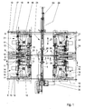
- FIG. 1 The schematically illustrated in Fig. 1 machine has a machine frame, which is the For clarity, not shown. In the machine, the rims are lying edited, d. H. in the middle of the machine there is a vertical central axis 1. It goes without saying that the machine can also be built or used rotated by 90 ° could, so with horizontally aligned center axis 1. However, it is only one Machine with vertical center axis 1 described.
- a hub 2 In the central axis 1, a hub 2 is shown. The flanges of the hub are recognizable. From one flange of the hub 2 is a single spoke 3 illustrates that to the upper Spoke series belongs. The upper row of spokes has 18 spokes. It becomes a machine described, which is designed for 36 spokes. It goes without saying that the lower one too Spoke series has 18 spokes, none of which is shown.
- the spoke 3 or the spokes lead from the hub 2 to a rim 4, in the cut and in the Half view is clarified.
- the rim 4 is with the outside of its one side wall in a reference plane 5 arranged. Parallel to this is a wheel plane 6 or rim plane shown.
- the wheel plane 6 is the median plane of the rim 4. The distance of the wheel plane.
- the reference plane 6 from the reference plane 5 corresponds to half the rim width. It is understood that at different widths 4 rims the distance between the reference plane 5 and 6 wheel plane varied. In the embodiment of the machine described here, the reference plane is the fifth fixed or held. It is always at the same height.
- the reference plane 5 as well as the wheel plane 6 are planes that are perpendicular to the vertical Center axis are arranged.
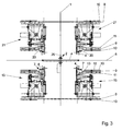
- the height of the reference plane 5 is by 18 lower clamping heads 7, which, as can be seen from the illustration of Fig. 2, in a mutual angular distance are provided by 20 ° evenly distributed over the circumference.
- the clamping heads 7 have a cylindrical portion (see also Fig. 3), whose upper end face a Form support for the rim side wall of the rim 4, so that thus the reference plane. 5 is determined. From this cylindrical side wall protrude upward conical extensions 8, which can engage behind the rim 4 and the one rim edge from the outside.
- the Clamping heads 7 are movable or movable in the radial direction to the central axis 1.
- the 18 lower clamping heads 7 are z. B. via a unit of a fixed plate 9 and a movable plate 10 moves radially, whereby the rim 4 centered to the central axis 1 becomes.
- Units of a fixed plate 9 and a movable plate 10 are in the Machine used four times and subsequently in conjunction with Figs. 5 and 6 im Individual explained.
- Each chuck 7 is seated on a slide rail 11.
- Each slide rail 11 is guided in plain bearings 12 and 13 radially to the central axis 1.
- the fixed plate 9 for the lower Clamping heads 7 is fixedly mounted or held on four columns 14, of which the For clarity, in Fig. 1, only two columns 14 are shown.
- the columns 14 are on a machine frame, not shown, provided and extend vertically, ie parallel to the median plane 1.
- each Clamping unit 15 has a fixed housing 16, which with a slide rail 17th connected is.
- Each slide 17 is in two plain bearings 18 and 19 radially to the central axis 1 led.
- the sliding bearings 18 and 19 are in turn arranged on a fixed plate 9, which cooperates with a movable plate 10.
- the solid plate unit 9 and movable plate 10 may be identical to the unit of the fixed plate 9 and the movable plate 10 may be formed in connection with the lower Clamping heads 7 has been described. Because these units are made up of fixed plates 9 and movable Plates 10 occur four times on the machine, they each have the same Reference signs, although it is so far multiply occurring parts. Also the fixed plate 9 for the clamping devices 15 is fixedly mounted on the columns 14, so that the vertical distance between the clamping units 15 and the lower clamping heads. 7 not changed. The fixed plate 9 of the clamping heads 7 and the fixed plate 9 of the clamping units 15 can additionally by one or more vertically arranged connection plates be stiffened, but not shown here for clarity. The Clamping heads 7 and the clamping units 15 are exclusively radial to the central axis. 1 traversable. They are not in a direction parallel to the axial extent of the units Center axis 1 movable.
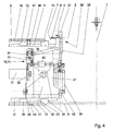
- the machine is with respect to the reference plane 5 and the wheel plane 6 under consideration an angle of 10 ° for 36 spokes symmetrically constructed. This will be particular illustrated by Fig. 3.
- Fig. 3 Just as there are lower clamping heads 7, there are also 18 upper ones Clamping heads 20.
- Each upper clamping head 20 is likewise mounted on a slide rail 11 and guided in plain bearings 12 and 13 radially to the vertical center axis 1. These too Movement is by a unit of a fixed plate 9 and a movable plate 10th brought about.
- the upper clamping heads 20 can be designed exactly like the lower ones Clamping heads 7, so with conical projections, the other side of the rim 4 of grab and center outside.
- the extensions 8 at the top To omit clamping heads 20, the clamping heads 20 slightly closer to the central axis position and only press against the outer end wall of the rim 4 to the Set rim 4 relative to the reference plane 5 and thus lateral impacts of the rim counteract.
- the centering effect and the compensation of the vertical strokes happens in in this case, only by the lower clamping heads. 7
- the upper clamping units 21 and the lower clamping units 15 are identical and vice versa arranged and also rotated by 10 °, that is approximately symmetrical to Reference plane 5 or wheel plane 6.
- Theceaspeichten wheels are so angle and true to the side turned with a transport device not shown in the machine introduced that the spokes of the lower row in one of the lower clamping units 15th assigned position and the spokes of the upper row simultaneously in one of the upper Clamping units 21 assigned position advised.
- the upper clamping units 21 have a housing 16 on a corresponding slide rail 17, the slide bearings 18th and 19 another unit of a fixed plate 9 and a movable plate 10 are guided radially.
- the unit of fixed plate 9 and movable plate 10, the upper Clamping 20 carry, and the unit of fixed plate 9 and movable plate 10, the Upper clamping units 21 carries are about one or more connecting plates 22 to connected to an overall mobile unit.
- This unit is according to double arrow 23 vertically movable, and relative to the stationary lower clamping heads 7 and lower clamping units 15. In this way, the machine can be opened.
- Fig. 3 shows at the same time such an open position in which a sprung wheel with hub 2, Rim 4 and the spokes 3 are retracted in the horizontal direction in the machine and on the end faces of the cylindrical portions of the lower clamping heads 8 are stored can.
- Fig. 3 shows at the same time such an open position in which a sprung wheel with hub 2, Rim 4 and the spokes 3 are retracted in the horizontal direction in the machine and on the end faces of the cylindrical portions of the lower clamping heads 8 are stored can.
- the rim 4 is shown three times, ie in the respective relative positions to the Elements to illustrate this, although of course only one wheel or a rim 4 is processed in the machine.
- the units of fixed plates 9 and movable plates 10 for the upper clamping heads 20 and the upper clamping units 21 are on the pillars fourteenth guided vertically.
- a sensor 24 for detecting the path or the position of the upper vertical be provided movable unit.
- the sensor 24 serves simultaneously for Detecting the rim width.
- the upper common unit will be via corresponding cylinders or also Servo motors moved vertically and controlled. In this case, a starting position can be controlled, such as Fig. 3 illustrates, as well as a working position, as Fig. 1 illustrates.
- the machine also includes means 25 for tightening the hub or axle 26 the hub 2 at both ends.
- two chucks 27 and 28 are provided.
- the Chuck 27 is disposed below the reference plane 5 and the wheel plane 6, the Chuck 28 above this level.
- the chucks 27 and 28 are again identical trained and arranged distributed symmetrically.
- the chuck 27 is located in a suitable starting position for gripping the lower end of the axis 26, while the upper chuck 28 is driven by an air cylinder 29 in the vertical direction.
- the Device 25 also has a sensor 53 for detecting the width of the hub 2 and the Display the position of the hub 2 according to the common method of the hub 2 on the closed chuck 27 and 28 relative to the rim 4 and the reference plane 5 on.
- a drive 30 which may be configured as a servomotor, in vertical Direction, ie in the central axis 1, arranged movable, so that the center axis. 1 centered retained hub in total in the appropriate relative position to the wheel plane. 6 procedure and can be kept fixed there.
- a single clamping unit 15 and 21 is shown.
- the clamping unit has a Housing 16 which is mounted on the slide rail 17 or connected thereto.
- the housing 16 carries a servomotor 31.
- the servomotor 31 is torque-controlled operated and allowed the exact approach of predetermined positions.
- the servomotor 31 has a pinion 32, of which an only schematically indicated belt 33 to a also mounted on the housing 16 wheel 34 leads.
- With the wheel 34 is a propeller shaft 35th rotatably connected, with the help of the rotary drive forwarded and in a housing part 36th in which a gear train of a plurality of gears (not shown) is arranged.
- the housing part 36 has at its upper end a fork 37, with which it can spread over a spoke.
- Such units are referred to as hands 38.
- the top gear of the gear train is slotted and drives a likewise Slotted nut on which a square surface to attack on the nipple on a spoke has.
- an air cylinder 39th intended for the vertical movement of the hand 38 relative to the housing 16.
- the little hand 38 is shown in its working position.
- Fig. 1 also Recognize the other position based on the representation of the propeller shaft 35, in which the Has moved out of the range of the spokes hands.
- nut with the square attack surface on the nipple can be according to the Make an inclined position to the respective spoke or nipple. So that the nut or the Hands 38 can be pushed onto the square surface of the nipple is one Radial movement to the central axis 1 required.
- an air cylinder 40 the at engages a pivot housing 41, which about a pivot axis 42 on the fixed Housing 16 is pivotable. This pivoting movement may well be for the radial Movement can be used to the central axis 1, since the hand 38 any angular adjustment allows.
- FIG. 4 also already leaves parts of the unit from the respective fixed plate 9 and the recognize respective movable plate 10.
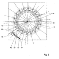
- FIGS. 4 to 6 pointed.
- the respective fixed plate 9 are elongated holes 43 which, like FIG. 6 can recognize, are arranged substantially radially.
- elongated holes 44 which are provided obliquely (Fig. 5).
- the long holes 43 and 44 partially or partially overlap and are associated with each other.
- the movable plate 10 is arranged only about the central axis 1 rotatably.
- tangentially arranged slots 45 are provided in the corresponding bolts on the respective fixed plate 9 (not shown) engage.
- the rotational movement of the movable plate 10 is controlled by a servomotor 48 on each movable plate 10.
- the Servomotor 48 is a gear 49 downstream, via which a spindle 50 driven is ultimately ending in a condyle 51, which ultimately at an engagement point 52 at the moving plate attacks. It is understood that at each slide 17 and 11 each one Bolt 46 is arranged with one roller 47, although only three rollers 47 shown in Fig. 5 are. This means that all units always center together to the center axis. 1 to be moved.
Landscapes
- Engineering & Computer Science (AREA)
- Mechanical Engineering (AREA)
- Jigs For Machine Tools (AREA)
- Testing Of Balance (AREA)
Abstract
Description
- Fig. 1
- zeigt eine schematisierte Vertikalansicht durch wesentliche Elemente der Maschine.
- Fig. 2
- zeigt eine Ansicht von Elementen der Maschine über den Umfang, also gemäß der Linie II-II in Fig. 1.
- Fig. 3
- zeigt eine ähnliche Darstellung wie Fig. 1, jedoch in etwas auseinandergezogener Darstellungsweise, um die Übersichtlichkeit und den symmetrischen Aufbau der Maschine zu verdeutlichen.
- Fig. 4
- zeigt eine Seitenansicht einer einzelnen Spanneinheit zum Verdrehen eines Nippels auf einer Speiche.
- Fig. 5
- zeigt eine Draufsicht auf eine bewegliche Platte zum zentrierenden Verfahren der Spanneinheiten und/oder der Spannköpfe.
- Fig. 6
- zeigt eine Darstellung der beweglichen Platte und der festen Platte übereinander.
- 1
- Mittelachse
- 2
- Nabe
- 3
- Speiche
- 4
- Felge
- 5
- Bezugsebene
- 6
- Radebene
- 7
- unterer Spannkopf
- 8
- Fortsatz
- 9
- feste Platte
- 10
- bewegliche Platte
- 11
- Gleitschiene
- 12
- Gleitlager
- 13
- Gleitlager
- 14
- Säule
- 15
- Spanneinheit
- 16
- Gehäuse
- 17
- Gleitschiene
- 18
- Gleitlager
- 19
- Gleitlager
- 20
- oberer Spannkopf
- 21
- obere Spanneinheit
- 22
- Verbindungsplatte
- 23
- Doppelpfeil
- 24
- Sensor
- 25
- Einrichtung
- 26
- Achse
- 27
- Spannfutter
- 28
- Spannfutter
- 29
- Luftzylinder
- 30
- Antrieb
- 31
- Servomotor
- 32
- Ritzel
- 33
- Riemen
- 34
- Rad
- 35
- Kardanwelle
- 36
- Gehäuseteil
- 37
- Gabel
- 38
- Händchen
- 39
- Luftzylinder
- 40
- Luftzylinder
- 41
- Schwenkgehäuse
- 42
- Schwenkachse
- 43
- Langloch
- 44
- Langloch
- 45
- Langloch
- 46
- Bolzen
- 47
- Rolle
- 48
- Servomotor
- 49
- Getriebe
- 50
- Spindel
- 51
- Gelenkkopf
- 52
- Angriffsstelle
- 53
- Sensor
Claims (10)
- Verfahren zum Spannen und Zentrieren von eingespeichten Rädern mit Nabe, Speichen und Felge, indem die Nabe (2) in einer Mittelachse (1) festgespannt und jeder Nippel auf der zugehörigen Speiche (3) unter Spannungsaufbau zur Felge (4) verdreht wird, dadurch gekennzeichnet, dass die Felge (4) auf eine Bezugsebene (5) aufgelegt und unter Zentrierwirkung zu der Mittelachse (1) der Nabe (2) festgespannt wird, dass eine sich aus der jeweiligen Felgenbreite ergebende Radebene (6) ermittelt und die festgespannte Nabe (2) in der Mittelachse (1) symmetrisch zu der Radebene (6) positioniert wird, und dass in der zentrierten Position der Nabe (2) und der Felge (4) alle Nippel auf den jeweiligen Speichen(3) gleichzeitig verdreht werden.
- Verfahren nach Anspruch 1, dadurch gekennzeichnet, dass in der zentrierten Position der Nabe (2) und der Felge (4) alle Nippel auf den jeweiligen Speichen (3) gleichzeitig drehmomentgesteuert verdreht werden.
- Verfahren nach Anspruch 1 oder 2, dadurch gekennzeichnet, dass die beiden Reihen der Nippel auf den Speichen (3) von den beiden Seiten relativ zur Radebene (6) gespannt werden.
- Maschine zum Spannen und Zentrieren von eingespeichten Rädern mit Nabe, Speichen und Felge, mit einer Einrichtung (25) zum Festspannen der Nabe (2) in einer Mittelachse (1), mit einer Vielzahl der Anzahl der Speichen (3) entsprechenden Spanneinheiten (15, 21) zum Verdrehen jeweils eines Nippels auf der zugehörigen Speiche (3), insbesondere nach mindestens einem der Ansprüche 1 bis 3, dadurch gekennzeichnet, dass die Einrichtung (25) zum Festspannen der Nabe (2) in der Mittelachse (1) verfahrbar ausgebildet ist, dass eine Einrichtung (7, 20) zum zentrierenden Festspannen der Felge (4) auf einer Bezugsebene (5) relativ zur Mittelachse (1) vorgesehen ist, und dass die Spanneinheiten (15, 21) auf beide Seiten der Bezugsebene (5) verteilt vorgesehen sind.
- Maschine nach Anspruch 4, dadurch gekennzeichnet, dass die Einrichtung (7, 20) zum zentrierenden Festspannen der Felge (4) relativ zur Mittelachse (1) auf einer Bezugsebene (5) eine zumindest der einfachen Anzahl der Speichen (3) entsprechende Vielzahl von Spannköpfen (7, 20) aufweist.
- Maschine nach mindestens einem der Ansprüche 4 oder 5, dadurch gekennzeichnet, dass die Einrichtung (25) zum Festspannen der Nabe (2) in der Mittelachse (1) zwei Spannfutter (27, 28) aufweist, die relativ zueinander und gemeinsam in der Mittelachse (1) verfahrbar sind.
- Maschine nach mindestens einem der Ansprüche 4 bis 6, dadurch gekennzeichnet, dass die Spannköpfe (27, 28) beidseitig der Bezugsebene (5) bzw. der Radebene (6) vorgesehen und radial zur Mittelachse (1) zentrierend verfahrbar sind, und dass zumindest die auf einer Seite der Bezugsebene (5) bzw. der Radebene (6) vorgesehenen Spannköpfe (20) auch in einer Richtung parallel zur Mittelachse (1) verfahrbar sind.
- Maschine nach mindestens einem der Ansprüche 4 bis 7, dadurch gekennzeichnet, dass die Maschine eine horizontal ausgerichtete und festgelegte Bezugsebene (5) aufweist, und dass die Spanneinheiten (15, 21) zum Verdrehen der Nippel, die Spannköpfe (7, 20) zum Zentrieren und Fixieren der Felge (4) sowie die Spannfutter (27, 28) zum Zentrieren der Achse (26) der Nabe (2) anzahlmäßig hälftig geteilt und symmetrisch zu der Bezugsebene (5) angeordnet sind.
- Maschine nach Anspruch 8, dadurch gekennzeichnet, dass die Spanneinheiten (21) zum Verdrehen der Nippel und die Spannköpfe (20) zum Zentrieren und Fixieren der Felge (4) auf der einen Seite der Bezugsebene (5) in einer Richtung (23) parallel zur Mittelachse (1) gemeinsam verfahrbar angeordnet sind, während die Spanneinheiten (15) zum Verdrehen der Nippel und die Spannköpfe (7) zum Zentrieren und Fixieren der Felge (4) auf der anderen Seite der Bezugsebene (5) in einer Richtung parallel zur Mittelachse (1) nicht verfahrbar angeordnet sind.
- Maschine nach mindestens einem der Ansprüche 4 bis 9, dadurch gekennzeichnet, dass Sensoren (53, 24) zum Erfassen der Wege und Positionen der Spannfutter (27, 28) und/oder der Spannköpfe (20) vorgesehen sind.
Applications Claiming Priority (2)
| Application Number | Priority Date | Filing Date | Title |
|---|---|---|---|
| DE102004008030 | 2004-02-19 | ||
| DE200410008030 DE102004008030B4 (de) | 2004-02-19 | 2004-02-19 | Verfahren zum Spannen und Zentrieren von eingespeichten Rädern sowie Maschine zur Durchführung des Verfahrens |
Publications (2)
| Publication Number | Publication Date |
|---|---|
| EP1566290A2 true EP1566290A2 (de) | 2005-08-24 |
| EP1566290A3 EP1566290A3 (de) | 2009-02-18 |
Family
ID=34706847
Family Applications (1)
| Application Number | Title | Priority Date | Filing Date |
|---|---|---|---|
| EP05003146A Withdrawn EP1566290A3 (de) | 2004-02-19 | 2005-02-15 | Verfahren zum Spannen und Zentrieren von eingespeichten Rädern sowie Maschine zur Durchführung des Verfahrens |
Country Status (2)
| Country | Link |
|---|---|
| EP (1) | EP1566290A3 (de) |
| DE (1) | DE102004008030B4 (de) |
Cited By (2)
| Publication number | Priority date | Publication date | Assignee | Title |
|---|---|---|---|---|
| NL2000142C2 (nl) * | 2006-07-12 | 2008-01-15 | Holland Mechanics Bv | Inrichting voor het richten van gespaakte wielen. |
| CN114310194A (zh) * | 2022-01-18 | 2022-04-12 | 长鹰信质科技股份有限公司 | 轮毂制造方法 |
Families Citing this family (4)
| Publication number | Priority date | Publication date | Assignee | Title |
|---|---|---|---|---|
| CN116214134A (zh) * | 2023-03-15 | 2023-06-06 | 佛山市悠潜乐科技有限公司 | 一种用于轮圈钢丝锁紧的工业机器人 |
| DE102024121854A1 (de) * | 2024-07-31 | 2026-02-05 | Bbs Automation Blaichach Gmbh | Maschine und Verfahren zum automatisierten Montieren von Speichenrädern, insbesondere Laufrädern von Fahrrädern |
| DE102024121832A1 (de) * | 2024-07-31 | 2026-02-05 | Bbs Automation Blaichach Gmbh | Maschine und Verfahren zum Montieren von Speichenrädern, insbesondere Laufrädern von Fahrrädern |
| DE102024121851A1 (de) * | 2024-07-31 | 2026-02-05 | Bbs Automation Blaichach Gmbh | Maschine und Verfahren zum automatisierten Montieren von Speichenrädern, insbesondere Laufrädern von Fahrrädern |
Family Cites Families (6)
| Publication number | Priority date | Publication date | Assignee | Title |
|---|---|---|---|---|
| US2759530A (en) * | 1951-03-15 | 1956-08-21 | Herr Equipment Corp | Apparatus for tensioning wire spokes on wheels |
| DE2003524B2 (de) * | 1969-04-21 | 1975-12-18 | Japan Bicycle Promotion Institute, Tokio | Vorrichtung zum gleichzeitigen Festziehen der Speichen von Drahtspeichenraedern |
| SE432910B (en) * | 1979-10-17 | 1984-04-30 | Roland Kaufeldt | Sett och anordning for automatisk atdragning av ekrar i ekerhjul |
| NL9201986A (nl) * | 1992-03-18 | 1993-10-18 | Holland Mechanics Bv | Inrichting voor het monteren van spaken tussen een naaf en velg van een spaakwiel. |
| DE19739336C2 (de) * | 1997-09-09 | 2000-02-24 | Guenter Golz | Zentriermaschine zum Nachspannen und Zentrieren von eingespeichten Laufrädern |
| DE19739365C2 (de) * | 1997-09-09 | 2000-02-24 | Guenter Golz | Vorrichtung zum Einspeichen eines Rades |
-
2004
- 2004-02-19 DE DE200410008030 patent/DE102004008030B4/de not_active Expired - Fee Related
-
2005
- 2005-02-15 EP EP05003146A patent/EP1566290A3/de not_active Withdrawn
Non-Patent Citations (1)
| Title |
|---|
| None |
Cited By (2)
| Publication number | Priority date | Publication date | Assignee | Title |
|---|---|---|---|---|
| NL2000142C2 (nl) * | 2006-07-12 | 2008-01-15 | Holland Mechanics Bv | Inrichting voor het richten van gespaakte wielen. |
| CN114310194A (zh) * | 2022-01-18 | 2022-04-12 | 长鹰信质科技股份有限公司 | 轮毂制造方法 |
Also Published As
| Publication number | Publication date |
|---|---|
| EP1566290A3 (de) | 2009-02-18 |
| DE102004008030A1 (de) | 2005-09-15 |
| DE102004008030B4 (de) | 2009-12-24 |
Similar Documents
| Publication | Publication Date | Title |
|---|---|---|
| DE69124438T2 (de) | Positioniervorrichtung | |
| EP0352599B1 (de) | Rollenrotations-Druckmaschine für spannkanallosen Endlosdruck | |
| EP1331059B1 (de) | Vorrichtung zum Spannen von Behältern und Verfahren zum Spannen, Positionieren und Bearbeiten von Behälter,Tonnen, Kesseln, Rohren und dergleichen unter verwendung einer solchen Vorrichtung | |
| DE10020702B4 (de) | Walzwerk, insbesondere Schräg- oder Diescherwalzwerk, in Modulbauweise | |
| DE102004008030B4 (de) | Verfahren zum Spannen und Zentrieren von eingespeichten Rädern sowie Maschine zur Durchführung des Verfahrens | |
| DE69803238T2 (de) | Abrichtmaschine | |
| DE2555604B2 (de) | Vorrichtung zum einstellen des gleichlaufs der walzenprofile eines werkzeugwalzenpaares an einer keilquerwalzmaschine | |
| WO2017121448A1 (de) | Positioniervorrichtung | |
| EP0857671A2 (de) | Einrichtung zum Wenden von Dosenkörpern | |
| DE1552780C3 (de) | Vorrichtung zum Richten unrunder Zahnkränze | |
| DE3936200C1 (de) | ||
| DE19739336C2 (de) | Zentriermaschine zum Nachspannen und Zentrieren von eingespeichten Laufrädern | |
| DD291507A5 (de) | Vorrichtung zum verstellen der falzklappen eines falzklappenzylinders | |
| EP0828572B1 (de) | Verfahren zum herstellen von ringförmigen werkstücken aus metall mit profiliertem querschnitt und walzwerk zu dessen durchführung | |
| DE2907282C2 (de) | Werkstückzu- und -abführeinrichtung an Maschinen zum Planschleifen | |
| EP1790423B1 (de) | Vorrichtung zum Halten von wenigstens zwei Walzen einer Walzmaschine und Walzmaschine | |
| DE19517100C2 (de) | Verfahren und Vorrichtung zum Einspeichen eines Rades mit einer Nabe und Speichen | |
| WO2009149916A1 (de) | Walzmaschine zum umformen von metallischen und/oder eisenhaltigen werkstücken und verfahren zum wechseln der walzen oder der walzwerkzeuge der walzmaschine | |
| DE102024121851A1 (de) | Maschine und Verfahren zum automatisierten Montieren von Speichenrädern, insbesondere Laufrädern von Fahrrädern | |
| DE3422524A1 (de) | Spann- und positioniervorrichtung fuer eine transfermaschine | |
| DE102024121854A1 (de) | Maschine und Verfahren zum automatisierten Montieren von Speichenrädern, insbesondere Laufrädern von Fahrrädern | |
| DE93181C (de) | ||
| DE4116621C1 (de) | ||
| DE1963150C3 (de) | Anlage zum Richten von als Rotationskörper mit Abstufungen gestalteten Werkstücken | |
| DE2003574A1 (de) | Futter zum Spannen duennwandiger Werkstuecke |
Legal Events
| Date | Code | Title | Description |
|---|---|---|---|
| PUAI | Public reference made under article 153(3) epc to a published international application that has entered the european phase |
Free format text: ORIGINAL CODE: 0009012 |
|
| AK | Designated contracting states |
Kind code of ref document: A2 Designated state(s): AT BE BG CH CY CZ DE DK EE ES FI FR GB GR HU IE IS IT LI LT LU MC NL PL PT RO SE SI SK TR |
|
| AX | Request for extension of the european patent |
Extension state: AL BA HR LV MK YU |
|
| PUAL | Search report despatched |
Free format text: ORIGINAL CODE: 0009013 |
|
| AK | Designated contracting states |
Kind code of ref document: A3 Designated state(s): AT BE BG CH CY CZ DE DK EE ES FI FR GB GR HU IE IS IT LI LT LU MC NL PL PT RO SE SI SK TR |
|
| AX | Request for extension of the european patent |
Extension state: AL BA HR LV MK YU |
|
| AKX | Designation fees paid | ||
| STAA | Information on the status of an ep patent application or granted ep patent |
Free format text: STATUS: THE APPLICATION IS DEEMED TO BE WITHDRAWN |
|
| 18D | Application deemed to be withdrawn |
Effective date: 20090619 |
|
| REG | Reference to a national code |
Ref country code: DE Ref legal event code: 8566 |