EP1566290A2 - Method for tensioning and centering of spoked wheels and a machine to carry out the method - Google Patents
Method for tensioning and centering of spoked wheels and a machine to carry out the method Download PDFInfo
- Publication number
- EP1566290A2 EP1566290A2 EP05003146A EP05003146A EP1566290A2 EP 1566290 A2 EP1566290 A2 EP 1566290A2 EP 05003146 A EP05003146 A EP 05003146A EP 05003146 A EP05003146 A EP 05003146A EP 1566290 A2 EP1566290 A2 EP 1566290A2
- Authority
- EP
- European Patent Office
- Prior art keywords
- rim
- hub
- clamping
- central axis
- centering
- Prior art date
- Legal status (The legal status is an assumption and is not a legal conclusion. Google has not performed a legal analysis and makes no representation as to the accuracy of the status listed.)
- Withdrawn
Links
Images


Classifications
-
- B—PERFORMING OPERATIONS; TRANSPORTING
- B60—VEHICLES IN GENERAL
- B60B—VEHICLE WHEELS; CASTORS; AXLES FOR WHEELS OR CASTORS; INCREASING WHEEL ADHESION
- B60B31/00—Apparatus or tools for assembling or disassembling wheels
- B60B31/02—Apparatus or tools for assembling or disassembling wheels for tightening or straightening wire spokes in situ; for extracting spokes from wheels
Definitions
- the invention relates to a method for tensioning and centeringtientspeichten wheels and a machine for carrying out the method.
- the invention can be particularly on the two wheels of bicycles, but also on wheelchairs and others Apply vehicles. It is always characteristic that the respective wheel is a hub and a rim interconnected by a plurality of spokes. Under a Rochespeichten wheel is understood a wheel in which the spokes in the Opened holes in the hub and through the openings in the rim passed through and on each spoke end a nipple is turned on that out Hub, spokes and rim is a loosely connected unit created.
- Such Wheel must be cocked and centered, with the nipples on the ends of the spokes like that must be rotated relative to each other, that a solid wheel unit is formed in which the Spokes in tight condition center the rim and the hub and under as possible connect small side and elevations.
- wheels in different impeller diameters for example in the range of 24 "to 28 ".
- the rims of any diameter size can also have different rim widths and have different rim depth.
- the vast majority of the wheels are in one Diameter range between 24 "and 28" and has 36 spokes.
- the 36 clamping units for the 36 nipples are on the arranged one side of a wheel plane laid by the wheel and obstruct each other each other especially when combining large hub diameter and smaller Rim diameter.
- In association with the 36 spokes are 18 lifting arms for lifting the Rim provided in a middle reference plane.
- Each lifting device is equipped with a displacement measuring device Mistake. It measures the side impacts and the lifting equipment operated with the swivel arms. As well as for the side impacts are too Sensors provided for measuring elevations.
- the rim is located in an eccentric position to a central axis.
- the machine is assigned a computer, which calculates the corresponding number of revolutions for each nipple, with the intention of to achieve a centering effect and a clamping effect.
- the invention is based on the object, a method for clamping and centering oftientspeichten wheels and a suitable device show with thetientspeichte Wheels of different diameters in a fixed diameter range, z. B. from 24 "to 28", with different rim widths, rim depths, hub widths and hub depths can be tensioned and centered in short working strokes.
- the Machine should also be capable of tolerances within a batch of wheels compensate.
- the axis of the hub is in a median plane tightened. This is done individually according to the length of the hub, with the axle fixed at both ends and thus forced into a central axis. It will be then a reference plane is formed, which is perpendicular to the central axis. The rim will be on this Placed reference plane, so that the one side of the rim or a part of it in the Reference plane comes to rest. The rim is then tightened on the reference plane. This is done so that the rim is centered at the same time to the central axis. Then, a wheel plane resulting from the respective rim width is determined. The Wheel plane represents the plane of symmetry through the rim.
- the reference plane and the Gear plane extend parallel and at a distance of half the rim width equivalent.
- the method allows very short work cycles.
- the machining of a wheel can be thereby shortening to an order of 10 seconds, so that compared to the stand the technology considerable increases in performance are possible.
- the quality of the clamping and Centering is generally sufficient to do without retightening and retanning get along.
- additional corrective measures are quite possible and also useful if overall smaller tolerances are to be maintained.
- the two rows of nipples on the spokes of the be stretched both sides relative to the wheel plane ago.
- the Clamping units arranged distributed on both sides of the wheel plane For 36 spokes, there are 18 Clamping units arranged on one side of the wheel plane and attack from there The nipples of one row of spokes, while the other 18 clamping units on the other side are arranged and intervene from there. This in turn means that for the arrangement of the clamping units sufficient space is available, so that these units do not interfere with each other.
- the through holes of the two Rows of spokes on the rim are often offset against each other, is a row Treatment of the nipples from the two sides also from the point of view of Force action makes sense. This work from both sides leaves no resulting Forces on the wheel arise. The forces balance out rather. This comes the tension and centering accuracy benefit.
- the hub is moved in the central axis so that it is centered in the intended relative position to the rim and in the axial direction the intended position. In this position then holds the institution to Tightening the hub fixed the hub and thus relative to the centered and also locked rim.
- It is also a device for centering the clamping Rim on a reference plane provided relative to the central axis.
- the reference plane forms a side plane of the rim.
- the reference plane is provided perpendicular to the central axis and fixed.
- the means for centering tightening the rim is at least partially actuated at each wheel to be machined, so moved, so that so a individual adaptation to tolerances is also possible within a series.
- the Clamping units are distributed on both sides of the reference plane or the gear plane provided and arranged. There is therefore enough building and working space for the Clamping units available. These no longer hinder each other and it is all hub and rim shapes and designs from the new machine too to process. Changeover times to other diameters are very low or eliminated. Rim diameter, Rim width, rim depth, hub width and hub depth can be selected as Parameters are input to a control and regulating device for the machine. One Part of these parameters can also be measured using sensors on the machine, so that in this regard incurred no changeover times. It can be the entire breadth of variation the wheels in a relatively large diameter range, in particular between 24 "and 28", are processed.
- the device for centering tightening the rim relative to the central axis on a Reference plane may correspond to at least the simple number of spokes Have variety of clamping heads.
- the clamping heads are located exactly where the Rim also has the through holes for the nipples. This means that everyone Spoke the rim is also held radially centered, causing the side and Radios are significantly reduced and reduced to an area where they do not to disturb. But it is also possible, the comparatively double the number of clamping heads provide, so z.
- clamping heads which also have a radial centering effect to exercise on the rim. Another possibility is centering only through half of the chucks and the other half of the chucks only to move according to axially parallel to the central axis. All clamping heads can be used radially Central axis may be arranged together or movable in the two groups. The one Half of the clamping heads is usually not in a direction parallel to the central axis movable, while the other half of the chucks on different rim widths Consideration.
- the device for tightening the hub in the central axis has two chucks, so that the axis of the hub is gripped at both ends and thus aligned with the central axis can be held.
- the two chucks are relatively movable, and although in the direction of the central axis.
- the two chucks are then together in The center axis movable to the hub in total in the intended relative position to bring the wheel centered to the center axis.
- the clamping heads are thus on both sides of the Provided reference plane or the wheel plane and centering radially to the central axis traversable. This mobility is used individually on each bike. For another so that different impeller diameters are processed.
- the on one side of the Reference plane or the gear plane provided clamping heads also in one direction parallel To the center axis are movable, this serves on the one hand the tightening of the rim in the centered position and on the other hand, the processing of different rim widths.
- the Reference plane is determined or determined by one half of the clamping heads. Depending on the rim widths are then different parallel to this reference plane Wheel planes. Under the wheel plane the plane of symmetry is understood by the rim.
- the machine has a horizontally oriented and fixed reference plane.
- the axis of the hub are each partially divided in half and symmetrical to the reference plane or the wheel plane arranged. In this way, not only the centering quality but the clamping units for twisting the nipples receive sufficient structural and movement space to all combinations of the designs of rims and Hubs take account. This also applies if, for example, a Hochflanschnabe to combine with a rim of relatively small diameter, with the spokes in a particularly pronounced skew advised. The combination of large rim diameters and small hub width and height is comparatively less critical.
- the machine has two groups of clamping units for twisting the nipples, ie z.
- the clamping units below the reference plane can be stationary be provided. This means that they are not movable in the direction of the central axis. It goes without saying that they are of course used to bridge different rim diameters must be movable radially to the central axis. Also in the axial direction must be elements the clamping device with respect to different rim widths to be movable.
- the Clamping units for twisting the nipples on the other side of the reference plane are in contrast, a total of movable in the direction of the central axis.
- sensors for detecting the paths and positions of the chuck and / or the Clamping heads provided.
- the sensors used to capture the paths and positions serve the chuck, in conjunction with a control and regulating device the exact relative position between hub and rim can be adjusted.
- a simple Position as it is common for example for front wheels of bicycles, is also the Hub positioned symmetrically to the wheel plane.
- the hub is eccentric to the wheel plane to one side something provided offset.
- the sensors on the clamping heads the respective rim width determined and thus the wheel plane to be determined. Also the definition of ways the clamping units to each other can be controlled with it.
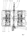
- FIG. 1 The schematically illustrated in Fig. 1 machine has a machine frame, which is the For clarity, not shown. In the machine, the rims are lying edited, d. H. in the middle of the machine there is a vertical central axis 1. It goes without saying that the machine can also be built or used rotated by 90 ° could, so with horizontally aligned center axis 1. However, it is only one Machine with vertical center axis 1 described.
- a hub 2 In the central axis 1, a hub 2 is shown. The flanges of the hub are recognizable. From one flange of the hub 2 is a single spoke 3 illustrates that to the upper Spoke series belongs. The upper row of spokes has 18 spokes. It becomes a machine described, which is designed for 36 spokes. It goes without saying that the lower one too Spoke series has 18 spokes, none of which is shown.
- the spoke 3 or the spokes lead from the hub 2 to a rim 4, in the cut and in the Half view is clarified.
- the rim 4 is with the outside of its one side wall in a reference plane 5 arranged. Parallel to this is a wheel plane 6 or rim plane shown.
- the wheel plane 6 is the median plane of the rim 4. The distance of the wheel plane.
- the reference plane 6 from the reference plane 5 corresponds to half the rim width. It is understood that at different widths 4 rims the distance between the reference plane 5 and 6 wheel plane varied. In the embodiment of the machine described here, the reference plane is the fifth fixed or held. It is always at the same height.
- the reference plane 5 as well as the wheel plane 6 are planes that are perpendicular to the vertical Center axis are arranged.
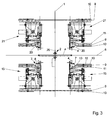
- the height of the reference plane 5 is by 18 lower clamping heads 7, which, as can be seen from the illustration of Fig. 2, in a mutual angular distance are provided by 20 ° evenly distributed over the circumference.
- the clamping heads 7 have a cylindrical portion (see also Fig. 3), whose upper end face a Form support for the rim side wall of the rim 4, so that thus the reference plane. 5 is determined. From this cylindrical side wall protrude upward conical extensions 8, which can engage behind the rim 4 and the one rim edge from the outside.
- the Clamping heads 7 are movable or movable in the radial direction to the central axis 1.
- the 18 lower clamping heads 7 are z. B. via a unit of a fixed plate 9 and a movable plate 10 moves radially, whereby the rim 4 centered to the central axis 1 becomes.
- Units of a fixed plate 9 and a movable plate 10 are in the Machine used four times and subsequently in conjunction with Figs. 5 and 6 im Individual explained.
- Each chuck 7 is seated on a slide rail 11.
- Each slide rail 11 is guided in plain bearings 12 and 13 radially to the central axis 1.
- the fixed plate 9 for the lower Clamping heads 7 is fixedly mounted or held on four columns 14, of which the For clarity, in Fig. 1, only two columns 14 are shown.
- the columns 14 are on a machine frame, not shown, provided and extend vertically, ie parallel to the median plane 1.
- each Clamping unit 15 has a fixed housing 16, which with a slide rail 17th connected is.
- Each slide 17 is in two plain bearings 18 and 19 radially to the central axis 1 led.
- the sliding bearings 18 and 19 are in turn arranged on a fixed plate 9, which cooperates with a movable plate 10.
- the solid plate unit 9 and movable plate 10 may be identical to the unit of the fixed plate 9 and the movable plate 10 may be formed in connection with the lower Clamping heads 7 has been described. Because these units are made up of fixed plates 9 and movable Plates 10 occur four times on the machine, they each have the same Reference signs, although it is so far multiply occurring parts. Also the fixed plate 9 for the clamping devices 15 is fixedly mounted on the columns 14, so that the vertical distance between the clamping units 15 and the lower clamping heads. 7 not changed. The fixed plate 9 of the clamping heads 7 and the fixed plate 9 of the clamping units 15 can additionally by one or more vertically arranged connection plates be stiffened, but not shown here for clarity. The Clamping heads 7 and the clamping units 15 are exclusively radial to the central axis. 1 traversable. They are not in a direction parallel to the axial extent of the units Center axis 1 movable.
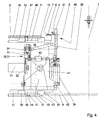
- the machine is with respect to the reference plane 5 and the wheel plane 6 under consideration an angle of 10 ° for 36 spokes symmetrically constructed. This will be particular illustrated by Fig. 3.
- Fig. 3 Just as there are lower clamping heads 7, there are also 18 upper ones Clamping heads 20.
- Each upper clamping head 20 is likewise mounted on a slide rail 11 and guided in plain bearings 12 and 13 radially to the vertical center axis 1. These too Movement is by a unit of a fixed plate 9 and a movable plate 10th brought about.
- the upper clamping heads 20 can be designed exactly like the lower ones Clamping heads 7, so with conical projections, the other side of the rim 4 of grab and center outside.
- the extensions 8 at the top To omit clamping heads 20, the clamping heads 20 slightly closer to the central axis position and only press against the outer end wall of the rim 4 to the Set rim 4 relative to the reference plane 5 and thus lateral impacts of the rim counteract.
- the centering effect and the compensation of the vertical strokes happens in in this case, only by the lower clamping heads. 7
- the upper clamping units 21 and the lower clamping units 15 are identical and vice versa arranged and also rotated by 10 °, that is approximately symmetrical to Reference plane 5 or wheel plane 6.
- Theceaspeichten wheels are so angle and true to the side turned with a transport device not shown in the machine introduced that the spokes of the lower row in one of the lower clamping units 15th assigned position and the spokes of the upper row simultaneously in one of the upper Clamping units 21 assigned position advised.
- the upper clamping units 21 have a housing 16 on a corresponding slide rail 17, the slide bearings 18th and 19 another unit of a fixed plate 9 and a movable plate 10 are guided radially.
- the unit of fixed plate 9 and movable plate 10, the upper Clamping 20 carry, and the unit of fixed plate 9 and movable plate 10, the Upper clamping units 21 carries are about one or more connecting plates 22 to connected to an overall mobile unit.
- This unit is according to double arrow 23 vertically movable, and relative to the stationary lower clamping heads 7 and lower clamping units 15. In this way, the machine can be opened.
- Fig. 3 shows at the same time such an open position in which a sprung wheel with hub 2, Rim 4 and the spokes 3 are retracted in the horizontal direction in the machine and on the end faces of the cylindrical portions of the lower clamping heads 8 are stored can.
- Fig. 3 shows at the same time such an open position in which a sprung wheel with hub 2, Rim 4 and the spokes 3 are retracted in the horizontal direction in the machine and on the end faces of the cylindrical portions of the lower clamping heads 8 are stored can.
- the rim 4 is shown three times, ie in the respective relative positions to the Elements to illustrate this, although of course only one wheel or a rim 4 is processed in the machine.
- the units of fixed plates 9 and movable plates 10 for the upper clamping heads 20 and the upper clamping units 21 are on the pillars fourteenth guided vertically.
- a sensor 24 for detecting the path or the position of the upper vertical be provided movable unit.
- the sensor 24 serves simultaneously for Detecting the rim width.
- the upper common unit will be via corresponding cylinders or also Servo motors moved vertically and controlled. In this case, a starting position can be controlled, such as Fig. 3 illustrates, as well as a working position, as Fig. 1 illustrates.
- the machine also includes means 25 for tightening the hub or axle 26 the hub 2 at both ends.
- two chucks 27 and 28 are provided.
- the Chuck 27 is disposed below the reference plane 5 and the wheel plane 6, the Chuck 28 above this level.
- the chucks 27 and 28 are again identical trained and arranged distributed symmetrically.
- the chuck 27 is located in a suitable starting position for gripping the lower end of the axis 26, while the upper chuck 28 is driven by an air cylinder 29 in the vertical direction.
- the Device 25 also has a sensor 53 for detecting the width of the hub 2 and the Display the position of the hub 2 according to the common method of the hub 2 on the closed chuck 27 and 28 relative to the rim 4 and the reference plane 5 on.
- a drive 30 which may be configured as a servomotor, in vertical Direction, ie in the central axis 1, arranged movable, so that the center axis. 1 centered retained hub in total in the appropriate relative position to the wheel plane. 6 procedure and can be kept fixed there.
- a single clamping unit 15 and 21 is shown.
- the clamping unit has a Housing 16 which is mounted on the slide rail 17 or connected thereto.
- the housing 16 carries a servomotor 31.
- the servomotor 31 is torque-controlled operated and allowed the exact approach of predetermined positions.
- the servomotor 31 has a pinion 32, of which an only schematically indicated belt 33 to a also mounted on the housing 16 wheel 34 leads.
- With the wheel 34 is a propeller shaft 35th rotatably connected, with the help of the rotary drive forwarded and in a housing part 36th in which a gear train of a plurality of gears (not shown) is arranged.
- the housing part 36 has at its upper end a fork 37, with which it can spread over a spoke.
- Such units are referred to as hands 38.
- the top gear of the gear train is slotted and drives a likewise Slotted nut on which a square surface to attack on the nipple on a spoke has.
- an air cylinder 39th intended for the vertical movement of the hand 38 relative to the housing 16.
- the little hand 38 is shown in its working position.
- Fig. 1 also Recognize the other position based on the representation of the propeller shaft 35, in which the Has moved out of the range of the spokes hands.
- nut with the square attack surface on the nipple can be according to the Make an inclined position to the respective spoke or nipple. So that the nut or the Hands 38 can be pushed onto the square surface of the nipple is one Radial movement to the central axis 1 required.
- an air cylinder 40 the at engages a pivot housing 41, which about a pivot axis 42 on the fixed Housing 16 is pivotable. This pivoting movement may well be for the radial Movement can be used to the central axis 1, since the hand 38 any angular adjustment allows.
- FIG. 4 also already leaves parts of the unit from the respective fixed plate 9 and the recognize respective movable plate 10.
- FIGS. 4 to 6 pointed.
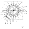
- the respective fixed plate 9 are elongated holes 43 which, like FIG. 6 can recognize, are arranged substantially radially.
- elongated holes 44 which are provided obliquely (Fig. 5).
- the long holes 43 and 44 partially or partially overlap and are associated with each other.
- the movable plate 10 is arranged only about the central axis 1 rotatably.
- tangentially arranged slots 45 are provided in the corresponding bolts on the respective fixed plate 9 (not shown) engage.
- the rotational movement of the movable plate 10 is controlled by a servomotor 48 on each movable plate 10.
- the Servomotor 48 is a gear 49 downstream, via which a spindle 50 driven is ultimately ending in a condyle 51, which ultimately at an engagement point 52 at the moving plate attacks. It is understood that at each slide 17 and 11 each one Bolt 46 is arranged with one roller 47, although only three rollers 47 shown in Fig. 5 are. This means that all units always center together to the center axis. 1 to be moved.
Abstract
Description
Die Erfindung betrifft ein Verfahren zum Spannen und Zentrieren von eingespeichten Rädern sowie eine Maschine zur Durchführung des Verfahrens. Die Erfindung lässt sich insbesondere auf die beiden Räder von Fahrrädern, aber auch auf Rollstühle und andere Fahrzeuge anwenden. Kennzeichnend ist dabei immer, dass das jeweilige Rad eine Nabe und eine Felge aufweist, die durch eine Vielzahl von Speichen miteinander verbunden sind. Unter einem eingespeichten Rad wird ein Rad verstanden, bei dem die Speichen in die Durchbrechungen der Nabe eingefädelt sowie durch die Durchbrechungen in der Felge hindurchgeführt sind und auf jede Speiche endseitig ein Nippel so aufgedreht ist, dass aus Nabe, Speichen und Felge eine lose zusammenhängende Einheit geschaffen ist. Ein solches Rad muss gespannt und zentriert werden, wobei die Nippel auf den Enden der Speichen so relativ zueinander verdreht werden müssen, dass eine feste Radeinheit entsteht, bei der die Speichen in gespanntem Zustand die Felge und die Nabe zentrieren und unter möglichst geringen Seiten- und Höhenschlägen verbinden.The invention relates to a method for tensioning and centering eingespeichten wheels and a machine for carrying out the method. The invention can be particularly on the two wheels of bicycles, but also on wheelchairs and others Apply vehicles. It is always characteristic that the respective wheel is a hub and a rim interconnected by a plurality of spokes. Under a eingespeichten wheel is understood a wheel in which the spokes in the Opened holes in the hub and through the openings in the rim passed through and on each spoke end a nipple is turned on that out Hub, spokes and rim is a loosely connected unit created. Such Wheel must be cocked and centered, with the nipples on the ends of the spokes like that must be rotated relative to each other, that a solid wheel unit is formed in which the Spokes in tight condition center the rim and the hub and under as possible connect small side and elevations.
Es gibt Räder in verschiedenen Laufraddurchmessern, beispielsweise im Bereich von 24" bis 28". Die Felgen jeder Durchmessergröße können darüber hinaus unterschiedliche Felgenbreite und unterschiedliche Felgentiefe aufweisen. Gleiches gilt für die Naben. Schließlich können auch noch die Anzahl der Speichen variieren. Somit gibt es eine große Vielzahl unterschiedlicher Räder. Die bei weitem überwiegende Anzahl der Räder liegt in einem Durchmesserbereich zwischen 24" und 28" und besitzt 36 Speichen. There are wheels in different impeller diameters, for example in the range of 24 "to 28 ". The rims of any diameter size can also have different rim widths and have different rim depth. The same applies to the hubs. After all can also vary the number of spokes. Thus, there is a great variety different wheels. The vast majority of the wheels are in one Diameter range between 24 "and 28" and has 36 spokes.
Es ist eine Maschine zum Spannen und Zentrieren von eingespeichten Rädern bekannt, bei denen die Nabe in einer Mittelachse durch eine Einrichtung festgespannt wird. Die lose mit der Nabe über die Speichen verbundene Felge wird auf eine Reihe von Schwenkarmen abgesenkt. Die Seitenschläge der Felge werden gemessen und die Schwenkarme in einer Richtung betätigt, die den Seitenschlägen entgegengerichtet ist. Für jede Speiche ist eine Spanneinrichtung vorgesehen, mit der der Nippel am Ende der Speiche unter Spannungsaufbau zur Felge weiter aufgedreht wird. Die Maschine ist für Räder mit 36 Speichen ausgelegt und gestattet es, in einem sehr kleinen Durchmesserbereich unterschiedliche Durchmessergrößen der Räder zu verarbeiten. Dies gilt auch für unterschiedliche Felgenbreiten und Felgentiefen. Jedoch müssen die zugehörigen Naben zu den Felgen in einem bestimmten Größenverhältnis stehen. Die 36 Spanneinheiten für die 36 Nippel sind auf der einen Seite einer durch das Rad gelegten Radebene angeordnet und behindern einander gegenseitig insbesondere bei der Kombination großer Nabendurchmesser und kleiner Felgendurchmesser. In Zuordnung zu den 36 Speichen sind 18 Hebearme zum Anheben der Felge in eine mittlere Bezugsebene vorgesehen. Jede Hebeeinrichtung ist mit einer Wegmesseinrichtung versehen. Es werden die Seitenschläge gemessen und die Hebeeinrichtungen mit den Schwenkarmen betätigt. Ebenso wie für die Seitenschläge sind auch Sensoren zum Messen von Höhenschlägen vorgesehen. Die Felge befindet sich dabei in einer exzentrischen Lage zu einer Mittelachse. Der Maschine ist ein Rechner zugeordnet, der die entsprechende Anzahl der Umdrehungen für jeden Nippel rechnet, in der Absicht, eine Zentrierwirkung und eine Spannwirkung zu erreichen. Die Vorgänge des Rechnens, Spannens, Messens laufen mehrmals hintereinander ab. Dabei werden auch Entspannungsvorgänge eingeschlossen, also das Zurückdrehen von Nippeln auf der jeweiligen Speiche. Für die Betätigung der Spanneinheiten ist eine Seilzugsteuerung vorgesehen. Der Drehantrieb der Spanneinrichtungen erfolgt über Gleichstrommotore und Kupplungen. Nachteilig an dieser bekannten Maschine ist es, dass nur ein sehr begrenzter Durchmesserbereich, abgestimmt auf bestimmte Naben, verarbeitbar ist. Die Leistung der Maschine ist begrenzt. Infolge der wiederholten Rechen-, Spann- und Messvorgänge dauert das Spannen und Zentrieren eines Rades etwa eine Minute.It is a machine known for clamping and centering of spoked wheels, at where the hub is clamped in a central axis by a device. The loose with The hub attached to the hub via the spokes is placed on a series of pivoting arms lowered. The side impacts of the rim are measured and the pivot arms in one Direction actuated, which is opposite to the lateral blows. For each spoke is one Clamping device provided with the nipple at the end of the spoke under tension to the rim is turned on. The machine is for wheels with 36 spokes designed and allows, in a very small diameter range different To process diameter sizes of the wheels. This also applies to different rim widths and rim depths. However, the associated hubs need to be rims in one certain size ratio stand. The 36 clamping units for the 36 nipples are on the arranged one side of a wheel plane laid by the wheel and obstruct each other each other especially when combining large hub diameter and smaller Rim diameter. In association with the 36 spokes are 18 lifting arms for lifting the Rim provided in a middle reference plane. Each lifting device is equipped with a displacement measuring device Mistake. It measures the side impacts and the lifting equipment operated with the swivel arms. As well as for the side impacts are too Sensors provided for measuring elevations. The rim is located in an eccentric position to a central axis. The machine is assigned a computer, which calculates the corresponding number of revolutions for each nipple, with the intention of to achieve a centering effect and a clamping effect. The processes of arithmetic, Spannens, Messens run several times in a row. It also relaxation processes included, so the turning back of nipples on the respective spoke. For the operation of the clamping units a cable control is provided. Of the Rotary drive of the clamping devices via DC motors and couplings. adversely in this known machine it is that only a very limited diameter range, matched to specific hubs, is processable. The performance of the machine is limited. As a result of the repeated computation, clamping and measuring processes, the clamping takes and centering a wheel about a minute.
Etwa 90 % aller Räder weisen 36 Speichen auf. Die Felgendurchmesser liegen in einem Bereich von 24" bis 28". Die Felgen besitzen unterschiedliche Felgenbreite und Felgenhöhe. Entsprechendes gilt für die zugeordneten Naben. Eine Maschine, die zum Spannen und Zentrieren von Rädern in dem aufgezeigten Bereich geeignet wäre, ist bisher nicht bekannt. Zwar gibt es Maschinen, die in aufwendiger und zeitraubender Weise umrüstbar sind. Diese arbeiten in der Regel mit einer sehr kleinen Anzahl von Spanneinheiten, so dass die 36 Nippel nacheinander gespannt werden müssen, was verfahrenstechnisch ohnehin ungünstig ist. Andererseits resultieren dabei erhebliche Bearbeitungszeiten für das einzelne Rad, so dass größere Leistungen damit nicht erzielbar sind. Oft ist auch die Qualität des Spann- und Zentriervorgangs unzureichend, so dass solche gespannten Räder noch einmal nachgespannt bzw. nachzentriert werden müssen.About 90% of all wheels have 36 spokes. The rim diameter is in one Range from 24 "to 28". The rims have different rim width and rim height. The same applies to the assigned hubs. A machine for clamping and Centering of wheels in the indicated area would be suitable, is not yet known. Although there are machines that can be retrofitted in a complex and time-consuming manner. These usually work with a very small number of clamping units, so the 36 Nipples must be tightened one after the other, which is technically unfavorable anyway is. On the other hand, this results in considerable processing times for the single wheel, so that larger services are therefore not achievable. Often, the quality of the clamping and Centering insufficient, so that tensioned wheels again tightened or to be re-centered.
Der Erfindung liegt die Aufgabe zugrunde, ein Verfahren zum Spannen und Zentrieren von eingespeichten Rädern und eine dazu geeignete Vorrichtung aufzuzeigen, mit der eingespeichte Räder mit unterschiedlichen Durchmessern in einem festgelegten Durchmesserbereich, z. B. von 24" bis 28", bei unterschiedlichen Felgenbreiten, Felgentiefen, Nabenbreiten und Nabentiefen in kurzen Arbeitstakten gespannt und zentriert werden können. Die Maschine soll auch geeignet sein, Toleranzen innerhalb einer Charge von Rädern auszugleichen.The invention is based on the object, a method for clamping and centering of eingespeichten wheels and a suitable device show with the eingespeichte Wheels of different diameters in a fixed diameter range, z. B. from 24 "to 28", with different rim widths, rim depths, hub widths and hub depths can be tensioned and centered in short working strokes. The Machine should also be capable of tolerances within a batch of wheels compensate.
Die Aufgabe der Erfindung wird erfindungsgemäß durch die Merkmale der unabhängigen
Patentansprüche 1 und 4 gelöst.The object of the invention is achieved by the features of the
Bei dem erfindungsgemäßen Verfahren wird die Achse der Nabe in einer Mittelebene festgespannt. Dies geschieht individuell entsprechend der Länge der Nabe, wobei die Achse an beiden Enden festgelegt und damit in eine Mittelachse gezwungen wird. Es wird dann eine Bezugsebene gebildet, die senkrecht zu der Mittelachse steht. Die Felge wird auf diese Bezugsebene aufgelegt, so dass die eine Seite der Felge oder ein Teil davon in der Bezugsebene zu liegen kommt. Die Felge wird dann auf der Bezugsebene festgespannt. Dies geschieht so, dass die Felge dabei gleichzeitig zu der Mittelachse zentriert wird. Sodann wird eine sich aus der jeweiligen Felgenbreite ergebende Radebene ermittelt. Die Radebene stellt die Symmetrieebene durch die Felge dar. Die Bezugsebene und die Radebene erstrecken sich parallel und in einem Abstand, der der halben Felgenbreite entspricht. Sobald die Felge zur Mittelachse zentriert festgespannt ist, wobei Seiten- und Höhenschlägen entgegengearbeitet wird bzw. diese ausgeglichen werden, wird nun die festgespannte Nabe in Richtung der Mittelachse so verfahren, dass die festgespannte Nabe in die gewünschte relative Position zu der Felge und damit der Radebene kommt. In vielen Fällen wird also die festgespannte Nabe in der Mittelachse symmetrisch zu der Radebene positioniert. Damit befinden sich die Nabe und die Felge in einer zentrierten Position zueinander. In dieser zentrierten Position werden nun alle Nippel auf den jeweiligen Speichen gleichzeitig verdreht, so dass die Speichen unter Spannung geraten und eine gespannte Radeinheit aus Nabe, Speichen und Felge entsteht. Durch das gleichzeitige Spannen erfolgt ein symmetrischer Spannungsaufbau, wobei die zentrierte Position zwischen Felge und Nabe stabilisiert wird. Es ist möglich, die Bezugsebene ohne Veränderung ihrer Position festzulegen und alle Bewegungsabläufe parallel zur Richtung der Mittelachse hierauf abzustimmen. In diesem Fall können einige Spanneinheiten ortsfest angeordnet werden. Gleiches gilt für einen Teil der Spannköpfe zum Zentrieren der Felge.In the method according to the invention, the axis of the hub is in a median plane tightened. This is done individually according to the length of the hub, with the axle fixed at both ends and thus forced into a central axis. It will be then a reference plane is formed, which is perpendicular to the central axis. The rim will be on this Placed reference plane, so that the one side of the rim or a part of it in the Reference plane comes to rest. The rim is then tightened on the reference plane. This is done so that the rim is centered at the same time to the central axis. Then, a wheel plane resulting from the respective rim width is determined. The Wheel plane represents the plane of symmetry through the rim. The reference plane and the Gear plane extend parallel and at a distance of half the rim width equivalent. Once the rim is centered clamped to the center axis, with side and Is counteracted or offset, is now the fixed hub in the direction of the central axis so that the tightened hub in the desired relative position to the rim and thus the wheel plane comes. In many Cases so the clamped hub in the central axis is symmetrical to the wheel plane positioned. This places the hub and rim in a centered position to each other. In this centered position, all nipples are now on the respective Twisted spokes at the same time, so that the spokes come under tension and a Tensioned wheel unit of hub, spokes and rim is created. By the simultaneous Clamping takes place a symmetrical stress build-up, with the centered position stabilized between the rim and hub. It is possible to use the reference plane without Define change in their position and all movements parallel to the direction of the Center axis to vote on this. In this case, some clamping units can be fixed to be ordered. The same applies to a part of the clamping heads for centering the rim.
Das Verfahren ermöglicht sehr kurze Arbeitstakte. Die Bearbeitung eines Rades kann sich dabei auf eine Größenordnung von 10 Sekunden verkürzen, so dass im Vergleich zum Stand der Technik erhebliche Leistungssteigerungen möglich sind. Die Güte des Spann- und Zentriervorgangs reicht im Allgemeinen aus, um ohne Nachspannen und Nachzentrieren auszukommen. Andererseits sind solche zusätzlichen Korrekturmaßnahmen durchaus möglich und auch sinnvoll, wenn insgesamt kleinere Toleranzen eingehalten werden sollen.The method allows very short work cycles. The machining of a wheel can be thereby shortening to an order of 10 seconds, so that compared to the stand the technology considerable increases in performance are possible. The quality of the clamping and Centering is generally sufficient to do without retightening and retanning get along. On the other hand, such additional corrective measures are quite possible and also useful if overall smaller tolerances are to be maintained.
Es ist vorteilhaft, die Nippel auf allen Speichen mehr oder weniger gleichzeitig und dabei drehmomentgesteuert zu verdrehen. Dies wirkt sich positiv auf ein gleichmäßiges Spannen über den Umfang des Randes aus.It is beneficial to use the nipples on all spokes more or less simultaneously while doing so to turn torque controlled. This has a positive effect on uniform clamping over the circumference of the edge.
Besonders vorteilhaft ist es, wenn die beiden Reihen der Nippel auf den Speichen von den beiden Seiten relativ zur Radebene her gespannt werden. Damit werden einerseits die Spanneinheiten zu beiden Seiten der Radebene verteilt angeordnet. Bei 36 Speichen sind 18 Spanneinheiten auf der einen Seite der Radebene angeordnet und greifen von dort aus an den Nippeln der einen Reihe der Speichen an, während die anderen 18 Spanneinheiten auf der anderen Seite angeordnet sind und von dort her eingreifen. Dies bedeutet wiederum, dass für die Anordnung der Spanneinheiten hinreichend Bauraum zur Verfügung steht, so dass sich diese Einheiten nicht gegenseitig behindern. Da die Durchgangslöcher der beiden Reihen der Speichen auf der Felge oft gegeneinander versetzt sind, ist eine reihenweise Behandlung der Nippel von den beiden Seiten her auch unter dem Gesichtspunkt der Krafteinwirkung sinnvoll. Dieses Arbeiten von beiden Seiten her lässt keine resultierenden Kräfte an dem Rad entstehen. Die Kräfte gleichen sich vielmehr aus. Dies kommt der Spann- und Zentriergenauigkeit zugute.It is particularly advantageous if the two rows of nipples on the spokes of the be stretched both sides relative to the wheel plane ago. Thus, on the one hand the Clamping units arranged distributed on both sides of the wheel plane. For 36 spokes, there are 18 Clamping units arranged on one side of the wheel plane and attack from there The nipples of one row of spokes, while the other 18 clamping units on the other side are arranged and intervene from there. This in turn means that for the arrangement of the clamping units sufficient space is available, so that these units do not interfere with each other. Because the through holes of the two Rows of spokes on the rim are often offset against each other, is a row Treatment of the nipples from the two sides also from the point of view of Force action makes sense. This work from both sides leaves no resulting Forces on the wheel arise. The forces balance out rather. This comes the tension and centering accuracy benefit.
Eine zum Spannen und Zentrieren von eingespeichten Rädern geeignete Maschine besitzt eine Einrichtung zum Festspannen der Nabe in einer Mittelachse und eine Anzahl von Spanneinheiten zum Verdrehen jeweils eines Nippels auf der zugehörigen Speiche. Die Vielzahl der Spanneinheiten entspricht der Anzahl der Speichen. Wenn die Maschine für 36 Speichen ausgelegt ist, sind 18 Spanneinheiten auf der einen Seite der Radebene und 18 Spanneinheiten auf der anderen Seite der Radebene vorgesehen. Es versteht sich, dass die Maschine auch für eine andere Anzahl von Speichen konstruiert bzw. ausgelegt werden kann. Es ist immer so, dass die Hälfte der Anzahl der Speichen, also eine Speichenreihe von der einen Seite und die andere Reihe der Speichen von der anderen Seite her bearbeitet wird. Die Einrichtung zum Festspannen der Nabe ist dagegen in der Mittelachse verfahrbar ausgebildet. Durch diese Verfahrbarkeit wird die Nabe in der Mittelachse so verfahren, dass sie in der vorgesehenen Relativlage zu der Felge zentriert ist und sich in axialer Richtung an der vorgesehenen Position befindet. In dieser Stellung hält dann die Einrichtung zum Festspannen der Nabe die Nabe fest und damit relativ zur zentrierten und ebenfalls festgehaltenen Felge. Es ist auch eine Einrichtung zum zentrierenden Festspannen der Felge auf eine Bezugsebene relativ zur Mittelachse vorgesehen. Die Bezugsebene bildet eine Seitenebene der Felge. Die Bezugsebene ist senkrecht zu der Mittelachse vorgesehen und festgelegt. Die Einrichtung zum zentrierenden Festspannen der Felge wird zumindest teilweise bei jedem zu bearbeitenden Rad betätigt, also bewegt, so dass damit eine individuelle Anpassung an Toleranzen auch innerhalb einer Baureihe möglich ist. Die Spanneinheiten sind auf beide Seiten der Bezugsebene bzw. der Radebene verteilt vorgesehen und angeordnet. Es steht daher genügend Bau- und Arbeitsraum für die Spanneinheiten zur Verfügung. Diese behindern sich nicht mehr gegenseitig und es sind sämtliche Naben- und Felgenformen und -gestaltungen von der neuen Maschine zu verarbeiten. Umrüstzeiten auf andere Durchmesser sind sehr gering oder entfallen. Felgendurchmesser, Felgenbreite, Felgentiefe, Nabenbreite und Nabentiefe können als wählbare Parameter in eine Steuer- und Regeleinrichtung für die Maschine eingegeben werden. Ein Teil dieser Parameter kann auch mit Sensoren an der Maschine jeweils gemessen werden, so dass diesbezüglich keine Umrüstzeiten anfallen. Es kann die gesamte Variationsbreite der Räder in einem relativ großen Durchmesserbereich, insbesondere zwischen 24" und 28", verarbeitet werden. Dies geschieht in relativ kurzen Taktzeiten in der Größenordnung von 10 Sekunden für ein Rad, so dass die Maschine eine sehr viel größere Leistung besitzt als bekannte Maschinen. Auch die Genauigkeit der Bearbeitung und die Qualität des Arbeitsergebnisses sind besser als im Stand der Technik. Eine wesentliche Ursache dafür ist das gleichzeitige Spannen sämtlicher Nippel anstelle eines Nacheinanderspannens.Has a suitable for clamping and centering eingespeichten wheels machine means for tightening the hub in a central axis and a number of Clamping units for turning one nipple each on the associated spoke. The Variety of clamping units corresponds to the number of spokes. If the machine is for 36 Spokes is designed 18 clamping units on one side of the wheel plane and 18 Clamping units provided on the other side of the wheel plane. It is understood that the Machine can also be designed or designed for a different number of spokes can. It is always that half of the number of spokes, so a series of spokes one side and the other row of spokes worked from the other side becomes. The device for tightening the hub, however, is movable in the central axis educated. By this mobility, the hub is moved in the central axis so that it is centered in the intended relative position to the rim and in the axial direction the intended position. In this position then holds the institution to Tightening the hub fixed the hub and thus relative to the centered and also locked rim. It is also a device for centering the clamping Rim on a reference plane provided relative to the central axis. The reference plane forms a side plane of the rim. The reference plane is provided perpendicular to the central axis and fixed. The means for centering tightening the rim is at least partially actuated at each wheel to be machined, so moved, so that so a individual adaptation to tolerances is also possible within a series. The Clamping units are distributed on both sides of the reference plane or the gear plane provided and arranged. There is therefore enough building and working space for the Clamping units available. These no longer hinder each other and it is all hub and rim shapes and designs from the new machine too to process. Changeover times to other diameters are very low or eliminated. Rim diameter, Rim width, rim depth, hub width and hub depth can be selected as Parameters are input to a control and regulating device for the machine. One Part of these parameters can also be measured using sensors on the machine, so that in this regard incurred no changeover times. It can be the entire breadth of variation the wheels in a relatively large diameter range, in particular between 24 "and 28", are processed. This happens in relatively short cycle times of the order of 10 Seconds for a wheel, so the machine has a much greater power than known machines. Also, the accuracy of the workmanship and the quality of the Work results are better than in the prior art. A major cause of this is the simultaneous tensioning of all nipples instead of one after another.
Die Einrichtung zum zentrierenden Festspannen der Felge relativ zur Mittelachse auf einer Bezugsebene kann eine zumindest der einfachen Anzahl der Speichen entsprechende Vielzahl von Spannköpfen aufweisen. Die Spannköpfe sind genau dort angeordnet, wo die Felge auch die Durchgangslöcher für die Nippel besitzt. Dies bedeutet, dass an jeder Speiche die Felge auch radial zentriert festgehalten ist, wodurch die Seiten- und Höhenschläge erheblich reduziert und in einen Bereich verringert werden, in dem sie nicht stören. Es ist aber auch möglich, die vergleichsweise doppelte Anzahl von Spannköpfen vorzusehen, also z. B. 72 Spannköpfe für eine auf 36 Speichen ausgelegte Maschine. Die einen 36 Spannköpfe greifen auf der einen Seite der Felge, also an der entsprechenden Felgenseitenwand, an. Die anderen 36 Spannköpfe greifen an der anderen Seitenwand der Felge an. Es ist möglich, nur Spannköpfe zu verwenden, die auch eine radiale Zentrierwirkung auf die Felge ausüben. Eine andere Möglichkeit besteht darin, die Zentrierung nur durch die Hälfte der Spannköpfe durchzuführen und die andere Hälfte der Spannköpfe nur entsprechend axial parallel zur Mittelachse zu bewegen. Alle Spannköpfe können radial zur Mittelachse gemeinsam oder in den beiden Gruppen bewegbar angeordnet sein. Die eine Hälfte der Spannköpfe ist in der Regel in einer Richtung parallel zur Mittelachse nicht beweglich, während die andere Hälfte der Spannköpfe auf unterschiedliche Felgenbreiten Rücksicht nimmt.The device for centering tightening the rim relative to the central axis on a Reference plane may correspond to at least the simple number of spokes Have variety of clamping heads. The clamping heads are located exactly where the Rim also has the through holes for the nipples. This means that everyone Spoke the rim is also held radially centered, causing the side and Radios are significantly reduced and reduced to an area where they do not to disturb. But it is also possible, the comparatively double the number of clamping heads provide, so z. B. 72 clamping heads for a machine designed for 36 spokes. The a 36 clamping heads grip on one side of the rim, so at the corresponding Rim sidewall, on. The other 36 clamping heads engage on the other side wall of the Rim on. It is possible to use only clamping heads, which also have a radial centering effect to exercise on the rim. Another possibility is centering only through half of the chucks and the other half of the chucks only to move according to axially parallel to the central axis. All clamping heads can be used radially Central axis may be arranged together or movable in the two groups. The one Half of the clamping heads is usually not in a direction parallel to the central axis movable, while the other half of the chucks on different rim widths Consideration.
Die Einrichtung zum Festspannen der Nabe in der Mittelachse weist zwei Spannfutter auf, so dass die Achse der Nabe an beiden Enden ergriffen und damit zur Mittelachse ausgerichtet gehalten werden kann. Hierzu sind die beiden Spannfutter relativ zueinander bewegbar, und zwar in Richtung der Mittelachse. Die beiden Spannfutter sind aber dann auch gemeinsam in der Mittelachse verfahrbar, um die Nabe insgesamt in die vorgesehene Relativposition zu der zur Mittelachse zentrierten Felge zu bringen. Die Spannköpfe sind damit beidseitig der Bezugsebene bzw. der Radebene vorgesehen und radial zur Mittelachse zentrierend verfahrbar. Diese Verfahrbarkeit wird individuell an jedem Rad genutzt. Zum anderen können damit unterschiedliche Laufraddurchmesser verarbeitet werden. Wenn die auf einer Seite der Bezugsebene bzw. der Radebene vorgesehenen Spannköpfe auch in einer Richtung parallel zur Mittelachse verfahrbar sind, dient dies einerseits dem Festspannen der Felge in der zentrierten Stellung und andererseits der Verarbeitung unterschiedlicher Felgenbreiten. Die Bezugsebene wird durch die eine Hälfte der Spannköpfe festgelegt bzw. bestimmt. Je nach den Felgenbreiten ergeben sich dann parallel zu dieser Bezugsebene unterschiedliche Radebenen. Unter der Radebene wird die Symmetrieebene durch die Felge verstanden.The device for tightening the hub in the central axis has two chucks, so that the axis of the hub is gripped at both ends and thus aligned with the central axis can be held. For this purpose, the two chucks are relatively movable, and although in the direction of the central axis. The two chucks are then together in The center axis movable to the hub in total in the intended relative position to bring the wheel centered to the center axis. The clamping heads are thus on both sides of the Provided reference plane or the wheel plane and centering radially to the central axis traversable. This mobility is used individually on each bike. For another so that different impeller diameters are processed. If the on one side of the Reference plane or the gear plane provided clamping heads also in one direction parallel To the center axis are movable, this serves on the one hand the tightening of the rim in the centered position and on the other hand, the processing of different rim widths. The Reference plane is determined or determined by one half of the clamping heads. Depending on the rim widths are then different parallel to this reference plane Wheel planes. Under the wheel plane the plane of symmetry is understood by the rim.
In besonders bevorzugter Ausführungsform weist die Maschine eine horizontal ausgerichtete und festgelegte Bezugsebene auf. Die Spanneinheiten zum Verdrehen der Nippel, die Spannköpfe zum Zentrieren und Fixieren der Felge sowie die Spannfutter zum Zentrieren der Achse der Nabe sind jeweils anteilmäßig hälftig geteilt und symmetrisch zu der Bezugsebene bzw. der Radebene angeordnet. Auf diese Weise wird nicht nur die Zentrierqualität gefördert, sondern die Spanneinheiten zum Verdrehen der Nippel erhalten genügend Bau- und Bewegungsraum, um sämtlichen Kombinationen der Gestaltungen von Felgen und Naben Rechnung zu tragen. Dies gilt auch dann, wenn beispielsweise eine Hochflanschnabe mit einer Felge mit relativ kleinem Durchmesser zu kombinieren ist, wobei die Speichen in eine besonders ausgeprägte Schräglage geraten. Die Kombination großer Felgendurchmesser und kleiner Nabenbreite und -höhe ist vergleichsweise weniger kritisch.In a particularly preferred embodiment, the machine has a horizontally oriented and fixed reference plane. The clamping units for twisting the nipples, the Clamping heads for centering and fixing the rim as well as the chucks for centering The axis of the hub are each partially divided in half and symmetrical to the reference plane or the wheel plane arranged. In this way, not only the centering quality but the clamping units for twisting the nipples receive sufficient structural and movement space to all combinations of the designs of rims and Hubs take account. This also applies if, for example, a Hochflanschnabe to combine with a rim of relatively small diameter, with the spokes in a particularly pronounced skew advised. The combination of large rim diameters and small hub width and height is comparatively less critical.
Die Maschine weist zwei Gruppen von Spanneinheiten zum Verdrehen der Nippel auf, also z. B. bei 36 Speichen 18 Spanneinheiten unterhalb der Bezugsebene und 18 Spanneinheiten oberhalb der Bezugsebene. Die Spanneinheiten unterhalb der Bezugsebene können ortsfest vorgesehen sein. Dies bedeutet, dass sie in Richtung der Mittelachse nicht verfahrbar sind. Es versteht sich, dass sie natürlich zur Überbrückung unterschiedlicher Felgendurchmesser radial zur Mittelachse beweglich sein müssen. Auch in axialer Richtung müssen Elemente der Spanneinrichtung im Hinblick auf unterschiedliche Felgenbreiten beweglich sein. Die Spanneinheiten zum Verdrehen der Nippel auf der anderen Seite der Bezugsebene sind dagegen insgesamt in Richtung der Mittelachse verfahrbar. Dies dient dazu, die Maschine zu öffnen und zu schließen, die Elemente in eine günstige Arbeitsposition zu bringen und trotzdem neue eingespeichte Räder nacheinander in die Maschine einzuführen, dort zu bearbeiten und wieder zu entnehmen. Für die Ausbildung und Anordnung der Spannköpfe zum Zentrieren und Fixieren der Felge gilt Entsprechendes, wie dies anhand der Spanneinheiten zum Verdrehen der Nippel bereits ausgeführt wurde. Es ist natürlich auch möglich, sämtliche Spanneinheiten und Spannköpfe in Richtung der Mittelachse verfahrbar anzuordnen. Damit erhöht sich der bauliche Aufwand entsprechend. Hierdurch wird dann eine Radebene dauerhaft festgelegt und es ergeben sich unterschiedliche Bezugsebenen je nach den unterschiedlichen Felgenbreiten.The machine has two groups of clamping units for twisting the nipples, ie z. For example, with 36 spokes, 18 clamping units below the reference plane and 18 clamping units above the reference plane. The clamping units below the reference plane can be stationary be provided. This means that they are not movable in the direction of the central axis. It goes without saying that they are of course used to bridge different rim diameters must be movable radially to the central axis. Also in the axial direction must be elements the clamping device with respect to different rim widths to be movable. The Clamping units for twisting the nipples on the other side of the reference plane are in contrast, a total of movable in the direction of the central axis. This serves to lock the machine open and close, bring the items into a favorable working position and still introduce new spoked wheels one after another in the machine, there to edit and remove again. For the training and arrangement of the clamping heads The same applies to centering and fixing the rim, as with the clamping units for twisting the nipple was already running. Of course it is also possible To arrange all clamping units and clamping heads in the direction of the central axis movable. This increases the construction costs accordingly. This will then become a Wheel plane permanently fixed and there are different reference levels depending on the different rim widths.
Es sind Sensoren zum Erfassen der Wege und Positionen der Spannfutter und/oder der Spannköpfe vorgesehen. Über die Sensoren, die zum Erfassen der Wege und der Positionen der Spannfutter dienen, kann in Verbindung mit einer Steuer- und Regeleinrichtung die genaue Relativposition zwischen Nabe und Felge eingestellt werden. In einer einfachen Position, wie es beispielsweise für Vorderräder von Fahrrädern gängig ist, wird auch die Nabe symmetrisch zur Radebene positioniert. Insbesondere bei angetriebenen Hinterrädern mit Zahnkränzen ist die Nabe jedoch außermittig zur Radebene nach der einen Seite etwas versetzt vorgesehen. Über die Sensoren an den Spannköpfen kann die jeweilige Felgenbreite ermittelt und damit die Radebene festgelegt werden. Auch die Festlegung der Wege der Spanneinheiten zueinander kann damit gesteuert werden. Es ist natürlich auch möglich, auf die Anordnung von Sensoren an den Spannköpfen zu verzichten und beispielsweise die Felgenbreite bei einer Serie zu bearbeitender Räder in die Steuereinrichtung als Parameter einzugeben. Auch andere Parameter können eingegeben werden, um so die Elemente der Maschine in eine Ausgangslage zu bringen, aus der heraus dann die Bearbeitung einer Serie von gleichen Rädern beginnt.There are sensors for detecting the paths and positions of the chuck and / or the Clamping heads provided. About the sensors used to capture the paths and positions serve the chuck, in conjunction with a control and regulating device the exact relative position between hub and rim can be adjusted. In a simple Position, as it is common for example for front wheels of bicycles, is also the Hub positioned symmetrically to the wheel plane. Especially with driven rear wheels with sprockets, however, the hub is eccentric to the wheel plane to one side something provided offset. About the sensors on the clamping heads, the respective rim width determined and thus the wheel plane to be determined. Also the definition of ways the clamping units to each other can be controlled with it. Of course it is also possible to dispense with the arrangement of sensors on the clamping heads and, for example, the Rim width in a series of wheels to be machined in the controller as a parameter enter. Other parameters can also be entered, so the elements of the Machine to bring into a starting position, out of the then processing a series starting from the same wheels.
Im Folgenden wird die Erfindung anhand in den Figuren dargestellter bevorzugter Ausführungsbeispiele weiter erläutert und beschrieben.
- Fig. 1
- zeigt eine schematisierte Vertikalansicht durch wesentliche Elemente der Maschine.
- Fig. 2
- zeigt eine Ansicht von Elementen der Maschine über den Umfang, also gemäß der Linie II-II in Fig. 1.
- Fig. 3
- zeigt eine ähnliche Darstellung wie Fig. 1, jedoch in etwas auseinandergezogener Darstellungsweise, um die Übersichtlichkeit und den symmetrischen Aufbau der Maschine zu verdeutlichen.
- Fig. 4
- zeigt eine Seitenansicht einer einzelnen Spanneinheit zum Verdrehen eines Nippels auf einer Speiche.
- Fig. 5
- zeigt eine Draufsicht auf eine bewegliche Platte zum zentrierenden Verfahren der Spanneinheiten und/oder der Spannköpfe.
- Fig. 6
- zeigt eine Darstellung der beweglichen Platte und der festen Platte übereinander.
- Fig. 1
- shows a schematic vertical view through essential elements of the machine.
- Fig. 2
- shows a view of elements of the machine over the circumference, ie according to the line II-II in Fig. 1st
- Fig. 3
- shows a similar representation as FIG. 1, but in a somewhat exploded view, to illustrate the clarity and the symmetrical design of the machine.
- Fig. 4
- shows a side view of a single clamping unit for rotating a nipple on a spoke.
- Fig. 5
- shows a plan view of a movable plate for centering method of the clamping units and / or the clamping heads.
- Fig. 6
- shows a representation of the movable plate and the fixed plate one above the other.
Die in Fig. 1 schematisch verdeutlichte Maschine besitzt ein Maschinengestell, welches der
Übersichtlichkeit halber nicht dargestellt ist. In der Maschine werden die Felgen liegend
bearbeitet, d. h. in der Mitte der Maschine befindet sich eine vertikale Mittelachse 1. Es
versteht sich, dass die Maschine auch um 90° gedreht gebaut bzw. eingesetzt werden
könnte, also mit horizontal ausgerichteter Mittelachse 1. Es wird nachfolgend jedoch nur eine
Maschine mit vertikaler Mittelachse 1 beschrieben.The schematically illustrated in Fig. 1 machine has a machine frame, which is the
For clarity, not shown. In the machine, the rims are lying
edited, d. H. in the middle of the machine there is a vertical
In der Mittelachse 1 ist eine Nabe 2 dargestellt. Die Flansche der Nabe sind erkennbar. Von
dem einen Flansch der Nabe 2 ist eine einzelne Speiche 3 verdeutlicht, die zu der oberen
Speichenreihe gehört. Die obere Speichenreihe besitzt 18 Speichen. Es wird eine Maschine
beschrieben, die für 36 Speichen konzipiert ist. Es versteht sich, dass auch die untere
Speichenreihe 18 Speichen aufweist, von denen jedoch keine dargestellt ist. Die Speiche 3
bzw. die Speichen führen von der Nabe 2 zu einer Felge 4, die im Schnitt sowie in der
Halbansicht verdeutlicht ist. Die Felge 4 ist mit der Außenseite ihrer einen Seitenwand in
einer Bezugsebene 5 angeordnet. Parallel dazu ist eine Radebene 6 oder Felgenebene
dargestellt. Die Radebene 6 ist die Mittelebene der Felge 4. Der Abstand der Radebene 6
von der Bezugsebene 5 entspricht der halben Felgenbreite. Es versteht sich, dass bei
unterschiedlich breiten Felgen 4 der Abstand zwischen Bezugsebene 5 und Radebene 6
variiert. Bei der hier beschriebenen Ausführungsform der Maschine ist die Bezugsebene 5
festgelegt bzw. festgehalten. Sie befindet sich immer auf der gleichen Höhe.In the
Die Bezugsebene 5 wie auch die Radebene 6 sind Ebenen, die senkrecht auf der vertikalen
Mittelachse angeordnet sind. Die Höhe der Bezugsebene 5 wird durch 18 untere Spannköpfe
7, die, wie aus der Darstellung der Fig. 2 erkennbar ist, in einem gegenseitigen Winkelabstand
von 20° gleichmäßig über den Umfang verteilt vorgesehen sind. Die Spannköpfe 7
besitzen einen zylindrischen Abschnitt (siehe auch Fig. 3), dessen obere Stirnfläche eine
Auflage für die Felgenseitenwand der Felge 4 bilden, so dass damit die Bezugsebene 5
festgelegt wird. Von dieser zylindrischen Seitenwand ragen nach oben kegelartige Fortsätze
8 ab, die die Felge 4 bzw. den einen Felgenrand von außen hintergreifen können. Die
Spannköpfe 7 sind in radialer Richtung zu der Mittelachse 1 bewegbar bzw. verfahrbar. Die
18 unteren Spannköpfe 7 werden dabei z. B. über eine Einheit aus einer festen Platte 9 und
einer beweglichen Platte 10 radial bewegt, wodurch die Felge 4 zur Mittelachse 1 zentriert
wird. Einheiten aus einer festen Platte 9 und einer beweglichen Platte 10 werden in der
Maschine vierfach eingesetzt und nachfolgend in Verbindung mit den Fig. 5 und 6 im
Einzelnen erläutert. Jeder Spannkopf 7 sitzt an einer Gleitschiene 11. Jede Gleitschiene 11
ist in Gleitlagern 12 und 13 radial zur Mittelachse 1 geführt. Die feste Platte 9 für die unteren
Spannköpfe 7 ist ortsfest an vier Säulen 14 gelagert bzw. gehalten, von denen der
Übersichtlichkeit halber in Fig. 1 nur zwei Säulen 14 dargestellt sind. Die Säulen 14 sind an
einem nicht dargestellten Maschinengestell vorgesehen und erstrecken sich vertikal, also
parallel zu der Mittelebene 1.The
Unterhalb der Gleitschienen 11 und unterhalb der Spannköpfe 7 sowie ohne Verbindung zu
diesen befinden sich 18 Spanneinheiten 15 zum Spannen, d. h. zum Verdrehen der Nippel
der unteren Speichenreihe. Eine einzelne Spanneinheit 15 ist in Fig. 4 verdeutlicht. Fig. 2
lässt erkennen, dass die Spanneinheiten 15 ebenso wie die unteren Spannköpfe 7 in einem
Winkel von 20° über den Umfang zueinander gleichmäßig verteilt angeordnet sind. Jede
Spanneinheit 15 weist ein festes Gehäuse 16 auf, welches mit einer Gleitschiene 17
verbunden ist. Jede Gleitschiene 17 ist in zwei Gleitlagern 18 und 19 radial zu der Mittelachse
1 geführt. Die Gleitlager 18 und 19 sind wiederum auf einer festen Platte 9 angeordnet,
die mit einer beweglichen Platte 10 zusammenarbeitet. Die Einheit aus fester Platte 9
und beweglicher Platte 10 kann identisch zu der Einheit aus der festen Platte 9 und der
beweglichen Platte 10 ausgebildet sein, die im Zusammenhang mit den unteren
Spannköpfen 7 beschrieben wurde. Da diese Einheiten aus festen Platten 9 und beweglichen
Platten 10 vierfach an der Maschine vorkommen, besitzen sie jeweils das gleiche
Bezugszeichen, obwohl es sich insoweit um mehrfach vorkommende Teile handelt. Auch die
feste Platte 9 für die Spanneinrichtungen 15 ist ortsfest an den Säulen 14 gelagert, so dass
sich der vertikale Abstand zwischen den Spanneinheiten 15 und den unteren Spannköpfen 7
nicht verändert. Die feste Platte 9 der Spannköpfe 7 und die feste Platte 9 der Spanneinheiten
15 können zusätzlich durch eine oder mehrere vertikal angeordnete Verbindungsplatten
ausgesteift sein, die hier der Übersichtlichkeit halber jedoch nicht dargestellt sind. Die
Spannköpfe 7 und die Spanneinheiten 15 sind ausschließlich radial zur Mittelachse 1
verfahrbar. Sie sind als Einheiten nicht in einer Richtung parallel zur axialen Erstreckung der
Mittelachse 1 verfahrbar.Below the slide rails 11 and below the clamping heads 7 and without connection to
these are 18 clamping
Die Maschine ist bezüglich der Bezugsebene 5 bzw. der Radebene 6 unter Berücksichtigung
eines Winkels von 10° für 36 Speichen symmetrisch aufgebaut. Dies wird insbesondere
durch Fig. 3 verdeutlicht. Ebenso wie es untere Spannköpfe 7 gibt, gibt es auch 18 obere
Spannköpfe 20. Jeder obere Spannkopf 20 ist ebenfalls auf einer Gleitschiene 11 gelagert
und in Gleitlagern 12 und 13 radial zur vertikalen Mittelachse 1 geführt. Auch diese
Bewegung wird durch eine Einheit aus einer festen Platte 9 und einer beweglichen Platte 10
herbeigeführt. Die oberen Spannköpfe 20 können genau so ausgebildet sein wie die unteren
Spannköpfe 7, also mit kegeligen Fortsätzen, die die andere Seitenwandung der Felge 4 von
außen ergreifen und zentrieren. Es ist jedoch bevorzugt, die Fortsätze 8 an den oberen
Spannköpfen 20 wegzulassen, die Spannköpfe 20 etwas näher zu der Mittelachse zu
positionieren und lediglich gegen die äußere Stirnwandung der Felge 4 anzudrücken, um die
Felge 4 relativ zur Bezugsebene 5 festzulegen und damit Seitenschlägen der Felge
entgegenzuwirken. Die Zentrierwirkung und der Ausgleich der Höhenschläge geschieht in
diesem Fall allein durch die unteren Spannköpfe 7.The machine is with respect to the
Ebenso wie es 18 untere Spanneinheiten 15 gibt, gibt es auch 18 obere Spanneinheiten 21.
Die oberen Spanneinheiten 21 und die unteren Spanneinheiten 15 sind identisch ausgebildet
und umgekehrt angeordnet sowie außerdem um 10° gedreht, also etwa symmetrisch zur
Bezugsebene 5 bzw. Radebene 6. Die eingespeichten Räder werden so winkel- und
seitenrichtig gedreht mit einer nicht dargestellten Transporteinrichtung in die Maschine
eingebracht, dass die Speichen der unteren Reihe in eine den unteren Spanneinheiten 15
zugeordnete Position und die Speichen der oberen Reihe gleichzeitig in eine den oberen
Spanneinheiten 21 zugeordnete Position geraten. Auch die oberen Spanneinheiten 21
besitzen ein Gehäuse 16 auf einer entsprechenden Gleitschiene 17, die in Gleitlagern 18
und 19 einer weiteren Einheit aus einer festen Platte 9 und einer beweglichen Platte 10
radial geführt sind. Die Einheit aus fester Platte 9 und beweglicher Platte 10, die die oberen
Spannköpfe 20 tragen, und die Einheit aus fester Platte 9 und beweglicher Platte 10, die die
oberen Spanneinheiten 21 trägt, sind über eine oder mehrere Verbindungsplatten 22 zu
einer insgesamt beweglichen Einheit verbunden. Diese Einheit ist gemäß Doppelpfeil 23
vertikal verfahrbar, und zwar relativ zu den stillstehenden unteren Spannköpfen 7 und
unteren Spanneinheiten 15. Auf diese Weise kann die Maschine geöffnet werden. Fig. 3
zeigt gleichzeitig eine solche Öffnungsstellung, in der ein eingespeichtes Rad mit Nabe 2,
Felge 4 und den Speichen 3 in horizontaler Richtung in die Maschine eingefahren und auf
die Stirnseiten der zylindrischen Abschnitte der unteren Spannköpfe 8 abgelegt werden
kann. In Fig. 3 ist die Felge 4 dreimal dargestellt, also in den jeweiligen Relativlagen zu den
Elementen, um dies zu verdeutlichen, obwohl natürlich nur immer ein Rad bzw. eine Felge 4
in der Maschine bearbeitet wird. Die Einheiten aus festen Platten 9 und beweglichen Platten
10 für die oberen Spannköpfe 20 und die oberen Spanneinheiten 21 sind auf den Säulen 14
vertikal geführt. Beispielsweise zwischen einer Säule 14 und einer Verbindungsplatte 22
kann ein Sensor 24 zum Erfassen des Weges bzw. der Position der oberen vertikal
verfahrbaren gemeinsamen Einheit vorgesehen sein. Der Sensor 24 dient gleichzeitig zum
Erfassen der Felgenbreite. Über eine hier nicht dargestellte Steuer- und Regeleinrichtung
wird die obere gemeinsame Einheit beispielsweise über entsprechende Zylinder oder auch
Servomotoren vertikal bewegt und gesteuert. Dabei ist eine Ausgangslage ansteuerbar, wie
sie Fig. 3 verdeutlicht, sowie eine Arbeitslage, wie sie Fig. 1 verdeutlicht.Just as there are 18
Die Maschine weist auch eine Einrichtung 25 zum Festspannen der Nabe bzw. der Achse 26
der Nabe 2 an beiden Enden auf. Hierzu sind zwei Spannfutter 27 und 28 vorgesehen. Das
Spannfutter 27 ist unterhalb der Bezugsebene 5 bzw. der Radebene 6 angeordnet, das
Spannfutter 28 oberhalb dieser Ebene. Die Spannfutter 27 und 28 sind wiederum identisch
ausgebildet und symmetrisch verteilt angeordnet. Das Spannfutter 27 befindet sich in einer
geeigneten Ausgangslage zum Ergreifen des unteren Endes der Achse 26, während das
obere Spannfutter 28 durch einen Luftzylinder 29 in vertikaler Richtung angetrieben wird. Die
Einrichtung 25 weist auch einen Sensor 53 zum Erfassen der Breite der Nabe 2 sowie zur
Anzeige der Position der Nabe 2 nach dem gemeinsamen Verfahren der Nabe 2 über die
geschlossenen Spannfutter 27 und 28 relativ zur Felge 4 bzw. der Bezugsebene 5 auf. The machine also includes
Sobald die beiden Spannfutter 27 und 28 Kontakt zu den entsprechenden Anlageflächen an
der Nabe 2 halten, schließen sich die Spannfutter 27 und 28 und die Achse 26 und damit
wird die Nabe 2 in der Mittelachse 1 zentriert gehalten. Die gesamte so gebildete Einrichtung
25 wird mit Hilfe eines Antriebes 30, der als Servomotor ausgebildet sein kann, in vertikaler
Richtung, also in der Mittelachse 1, verfahrbar angeordnet, damit die zur Mittelachse 1
zentriert festgehaltene Nabe insgesamt in die geeignete Relativposition zu der Radebene 6
verfahren und dort fixiert gehalten werden kann. Damit ist erkennbar, dass die Nabe 2 und
die Felge 4 zentriert zueinander und in der vorgesehenen Relativposition fixierbar sind, so
dass dann die Spanneinheiten 15 und 21 zum Verdrehen der Nippel auf sämtlichen
Speichen gleichzeitig eingesetzt werden können, so dass aus der losen Einheit aus Nabe 2,
Speichen 3 und Felge 4 eine gespannte Laufradeinheit entsteht.As soon as the two
In Fig. 4 ist eine einzelne Spanneinheit 15 bzw. 21 dargestellt. Die Spanneinheit weist ein
Gehäuse 16 auf, welches auf der Gleitschiene 17 gelagert bzw. mit dieser verbunden ist.
Das Gehäuse 16 trägt einen Servomotor 31. Der Servomotor 31 wird drehmomentgesteuert
betrieben und erlaubt das genaue Anfahren vorher festgelegter Positionen. Der Servomotor
31 besitzt ein Ritzel 32, von dem ein nur schematisch angedeuteter Riemen 33 zu einem
ebenfalls am Gehäuse 16 gelagerten Rad 34 führt. Mit dem Rad 34 ist eine Kardanwelle 35
drehfest verbunden, mit deren Hilfe der Drehantrieb weitergeleitet und in ein Gehäuseteil 36
übertragen wird, in welchem ein Zahnradzug aus mehreren Zahnrädern (nicht dargestellt)
angeordnet ist. Das Gehäuseteil 36 besitzt an seinem oberen Ende eine Gabel 37, mit der es
über eine Speiche übergreifen kann. Solche Einheiten werden als Händchen 38 bezeichnet.
Das oberste Zahnrad des Getriebezuges ist geschlitzt ausgebildet und treibt eine ebenfalls
geschlitzte Nuss an, die eine Vierkantfläche zum Angriff an dem Nippel auf einer Speiche
besitzt. Durch die in Fig. 4 ersichtliche Relativlage ist erkennbar, dass das Händchen 38 aus
dem Innenraum der Felge 4 heraus an dem nicht dargestellten Nippel angreift. Auf diese
Weise wird der Nippel auf der betreffenden Speiche verdreht und dabei gespannt.In Fig. 4, a
Für die Vertikalbewegung des Händchens 38 relativ zum Gehäuse 16 ist ein Luftzylinder 39
vorgesehen. Das Händchen 38 ist in seiner Arbeitsstellung dargestellt. Fig. 1 lässt auch
anhand der Darstellung der Kardanwelle 35 die andere Stellung erkennen, in welcher das
Händchen aus dem Erstreckungsbereich der Speichen herausgefahren ist. Die nicht
dargestellte Nuss mit der Vierkant-Angriffsfläche an dem Nippel kann sich entsprechend der
Schräglage an die jeweilige Speiche bzw. den Nippel anlegen. Damit die Nuss bzw. das
Händchen 38 auf die Vierkantfläche des Nippels aufgeschoben werden kann, ist eine
Radialbewegung zur Mittelachse 1 erforderlich. Hierzu dient ein Luftzylinder 40, der an
einem Schwenkgehäuse 41 angreift, welches um eine Schwenkachse 42 an dem festen
Gehäuse 16 schwenkbar ist. Diese Schwenkbewegung kann durchaus für die radiale
Bewegung zur Mittelachse 1 genutzt werden, da das Händchen 38 jegliche Winkelanpassung
ermöglicht.For the vertical movement of the
Fig. 4 lässt auch bereits Teile der Einheit aus der jeweiligen festen Platte 9 und der
jeweiligen beweglichen Platte 10 erkennen. In diesem Zusammenhang wird auf die Fig. 4 bis
6 hingewiesen. In der jeweiligen festen Platte 9 befinden sich Langlöcher 43, die, wie Fig. 6
erkennen lässt, im Wesentlichen radial angeordnet sind. In der beweglichen Platte 10
befinden sich Langlöcher 44, die schräg verlaufend (Fig. 5) vorgesehen sind. Die Langlöcher
43 und 44 überdecken sich teilweise bzw. bereichsweise und sind einander zugeordnet. Die
bewegliche Platte 10 ist lediglich um die Mittelachse 1 drehbar angeordnet. Um diese
Drehbarkeit zu ermöglichen, sind tangential angeordnete Langlöcher 45 vorgesehen, in die
entsprechende Bolzen an der jeweiligen festen Platte 9 (nicht dargestellt) eingreifen. An der
jeweiligen Gleitschiene 17 bzw. 11 sind Bolzen 46 befestigt, die die Langlöcher 43 durchsetzen
und mit Hilfe einer Rolle 47 oder eines Kugellagers in die Langlöcher 44 der beweglichen
Platte 10 eingreifen. Damit wird erkennbar, dass bei Verdrehung der beweglichen
Platte 10 um die Mittelachse 1 die betreffenden Gleitschienen 17 bzw. 11 eine gesteuerte
radiale Bewegung auf die Mittelachse 1 bzw. in der Gegenrichtung dazu ausüben. Diese
Bewegung wird hinsichtlich der Spannköpfe 7 und 20 für die Zentrierung der Felge 4 genutzt.
Bezüglich der Spanneinheiten 15 und 21 dient diese Bewegung dazu, die Händchen 38 in
dem Innenraum der Felge 4 zu platzieren, um von innen an den Nippeln angreifen zu
können. Dies geschieht wiederum in Abhängigkeit von den verschiedenen Laufraddurchmessern
bzw. Felgendurchmessern. Die Drehbewegung der beweglichen Platte 10 wird
durch einen Servomotor 48 an jeder beweglichen Platte 10 gesteuert herbeigeführt. Dem
Servomotor 48 ist ein Getriebe 49 nachgeordnet, über welches eine Spindel 50 angetrieben
wird, die letztlich in einem Gelenkkopf 51 endet, der letztlich an einer Eingriffsstelle 52 an der
beweglichen Platte angreift. Es versteht sich, dass an jeder Gleitschiene 17 bzw. 11 je ein
Bolzen 46 mit je einer Rolle 47 angeordnet ist, obwohl in Fig. 5 nur drei Rollen 47 dargestellt
sind. Dies bedeutet, dass alle Einheiten immer gemeinsam zentrierend zu der Mittelachse 1
bewegt werden. Fig. 4 also already leaves parts of the unit from the respective fixed
- 11
- Mittelachsecentral axis
- 22
- Nabehub
- 33
- Speichespoke
- 44
- Felgerim
- 55
- Bezugsebenereference plane
- 66
- Radebenewheel plane
- 77
- unterer Spannkopflower clamping head
- 88th
- Fortsatzextension
- 99
- feste Plattesolid plate
- 1010
- bewegliche Plattemovable plate
- 1111
- Gleitschieneslide
- 1212
- Gleitlagerbearings
- 1313
- Gleitlagerbearings
- 1414
- Säulepillar
- 1515
- Spanneinheitclamping unit
- 1616
- Gehäusecasing
- 1717
- Gleitschieneslide
- 1818
- Gleitlagerbearings
- 1919
- Gleitlagerbearings
- 2020
- oberer Spannkopfupper clamping head
- 2121
- obere Spanneinheitupper clamping unit
- 2222
- Verbindungsplatteconnecting plate
- 2323
- Doppelpfeildouble arrow
- 2424
- Sensorsensor
- 2525
- EinrichtungFacility
- 2626
- Achseaxis
- 2727
- Spannfutterchuck
- 2828
- Spannfutterchuck
- 2929
- Luftzylinderair cylinder
- 3030
- Antriebdrive
- 3131
- Servomotorservomotor
- 3232
- Ritzelpinion
- 3333
- Riemenbelt
- 3434
- Radwheel
- 3535
- Kardanwellepropeller shaft
- 3636
- Gehäuseteilhousing part
- 3737
- Gabelfork
- 3838
- Händchenhands
- 3939
- Luftzylinderair cylinder
- 4040
- Luftzylinderair cylinder
- 4141
- Schwenkgehäuseswivel case
- 4242
- Schwenkachseswivel axis
- 4343
- LanglochLong hole
- 4444
- LanglochLong hole
- 4545
- LanglochLong hole
- 4646
- Bolzenbolt
- 4747
- Rollerole
- 4848
- Servomotorservomotor
- 4949
- Getriebetransmission
- 5050
- Spindelspindle
- 5151
- Gelenkkopfjoint head
- 5252
- Angriffsstellepoint of attack
- 5353
- Sensorsensor
Claims (10)
Applications Claiming Priority (2)
| Application Number | Priority Date | Filing Date | Title |
|---|---|---|---|
| DE200410008030 DE102004008030B4 (en) | 2004-02-19 | 2004-02-19 | Method for tensioning and centering spoked wheels and machine for carrying out the method |
| DE102004008030 | 2004-02-19 |
Publications (2)
| Publication Number | Publication Date |
|---|---|
| EP1566290A2 true EP1566290A2 (en) | 2005-08-24 |
| EP1566290A3 EP1566290A3 (en) | 2009-02-18 |
Family
ID=34706847
Family Applications (1)
| Application Number | Title | Priority Date | Filing Date |
|---|---|---|---|
| EP05003146A Withdrawn EP1566290A3 (en) | 2004-02-19 | 2005-02-15 | Method for tensioning and centering of spoked wheels and a machine to carry out the method |
Country Status (2)
| Country | Link |
|---|---|
| EP (1) | EP1566290A3 (en) |
| DE (1) | DE102004008030B4 (en) |
Cited By (2)
| Publication number | Priority date | Publication date | Assignee | Title |
|---|---|---|---|---|
| NL2000142C2 (en) * | 2006-07-12 | 2008-01-15 | Holland Mechanics Bv | Device for aligning spoked wheels. |
| CN114310194A (en) * | 2022-01-18 | 2022-04-12 | 长鹰信质科技股份有限公司 | Hub manufacturing method |
Families Citing this family (1)
| Publication number | Priority date | Publication date | Assignee | Title |
|---|---|---|---|---|
| CN116214134A (en) * | 2023-03-15 | 2023-06-06 | 佛山市悠潜乐科技有限公司 | Industrial robot for locking rim steel wire |
Family Cites Families (6)
| Publication number | Priority date | Publication date | Assignee | Title |
|---|---|---|---|---|
| US2759530A (en) * | 1951-03-15 | 1956-08-21 | Herr Equipment Corp | Apparatus for tensioning wire spokes on wheels |
| DE2003524B2 (en) * | 1969-04-21 | 1975-12-18 | Japan Bicycle Promotion Institute, Tokio | Spoked wheel assembly machine - has rim held rigidly by frame whilst spokes tensioned to preset torque by radial tool |
| SE432910B (en) * | 1979-10-17 | 1984-04-30 | Roland Kaufeldt | Sett och anordning for automatisk atdragning av ekrar i ekerhjul |
| NL9201986A (en) * | 1992-03-18 | 1993-10-18 | Holland Mechanics Bv | Device for mounting spokes between a hub and rim of a spoke wheel. |
| DE19739336C2 (en) * | 1997-09-09 | 2000-02-24 | Guenter Golz | Centering machine for re-tensioning and centering spoked wheels |
| DE19739365C2 (en) * | 1997-09-09 | 2000-02-24 | Guenter Golz | Device for storing a wheel |
-
2004
- 2004-02-19 DE DE200410008030 patent/DE102004008030B4/en not_active Expired - Fee Related
-
2005
- 2005-02-15 EP EP05003146A patent/EP1566290A3/en not_active Withdrawn
Non-Patent Citations (1)
| Title |
|---|
| None |
Cited By (2)
| Publication number | Priority date | Publication date | Assignee | Title |
|---|---|---|---|---|
| NL2000142C2 (en) * | 2006-07-12 | 2008-01-15 | Holland Mechanics Bv | Device for aligning spoked wheels. |
| CN114310194A (en) * | 2022-01-18 | 2022-04-12 | 长鹰信质科技股份有限公司 | Hub manufacturing method |
Also Published As
| Publication number | Publication date |
|---|---|
| DE102004008030B4 (en) | 2009-12-24 |
| EP1566290A3 (en) | 2009-02-18 |
| DE102004008030A1 (en) | 2005-09-15 |
Similar Documents
| Publication | Publication Date | Title |
|---|---|---|
| EP0352599B1 (en) | Web-fed press for continuously printing without using a tensioning channel | |
| EP1331059B1 (en) | Fastening device for containers and processes for clamping, positioning and processing containers, barrels, cauldrons, tubes and similar using such a fastening device | |
| EP1068917A2 (en) | Device and method for machining crankpins | |
| EP1566290A2 (en) | Method for tensioning and centering of spoked wheels and a machine to carry out the method | |
| DE10020702B4 (en) | Rolling mill, in particular inclined or Diescherwalzwerk, in modular design | |
| CH419800A (en) | Machine for the finishing of gears | |
| WO2017121448A1 (en) | Positioning apparatus | |
| DE2555604B2 (en) | DEVICE FOR ADJUSTING THE CONTINUOUS RUNNING OF THE ROLLER PROFILES OF A PAIR OF TOOL ROLLERS ON A WEDGE CROSS ROLLING MACHINE | |
| DE2529343A1 (en) | Tyre fitting and removal rig - with contoured roller to exert even pressure on tyre walls carried by turntable | |
| DE1552780C3 (en) | Device for straightening out-of-round gear rims | |
| EP1790423B1 (en) | Holding device for the at least two rollers of a rolling machine and rolling machine | |
| DE3936200C1 (en) | ||
| DE19739336C2 (en) | Centering machine for re-tensioning and centering spoked wheels | |
| DD291507A5 (en) | DEVICE FOR ADJUSTING THE FOLDING FLAPS OF A FOLDING CYLINDER | |
| EP0828572B1 (en) | Process for producing annular work pieces from metal with a profiled cross-section and a rolling facility for carrying out the method | |
| DE2907282C2 (en) | Workpiece infeed and unloading device on machines for surface grinding | |
| DE202011103051U1 (en) | Hub-rotating device, in particular for use in the bodywork of the automotive industry | |
| DE19517100C2 (en) | Method and device for storing a wheel with a hub and spokes | |
| WO2009149916A1 (en) | Rolling machine for shaping metallic and/or iron-containing workpieces and method for changing the rolls or the rolling tools of the rolling machine | |
| EP0857671A2 (en) | Device for turning can bodies | |
| DE3422524A1 (en) | Tensioning and positioning device for a transfer machine | |
| DE93181C (en) | ||
| DE4116621C1 (en) | ||
| DE1963150C3 (en) | System for straightening workpieces designed as rotating bodies with gradations | |
| DE2003574A1 (en) | Chuck for clamping thin-walled workpieces |
Legal Events
| Date | Code | Title | Description |
|---|---|---|---|
| PUAI | Public reference made under article 153(3) epc to a published international application that has entered the european phase |
Free format text: ORIGINAL CODE: 0009012 |
|
| AK | Designated contracting states |
Kind code of ref document: A2 Designated state(s): AT BE BG CH CY CZ DE DK EE ES FI FR GB GR HU IE IS IT LI LT LU MC NL PL PT RO SE SI SK TR |
|
| AX | Request for extension of the european patent |
Extension state: AL BA HR LV MK YU |
|
| PUAL | Search report despatched |
Free format text: ORIGINAL CODE: 0009013 |
|
| AK | Designated contracting states |
Kind code of ref document: A3 Designated state(s): AT BE BG CH CY CZ DE DK EE ES FI FR GB GR HU IE IS IT LI LT LU MC NL PL PT RO SE SI SK TR |
|
| AX | Request for extension of the european patent |
Extension state: AL BA HR LV MK YU |
|
| AKX | Designation fees paid | ||
| STAA | Information on the status of an ep patent application or granted ep patent |
Free format text: STATUS: THE APPLICATION IS DEEMED TO BE WITHDRAWN |
|
| 18D | Application deemed to be withdrawn |
Effective date: 20090619 |
|
| REG | Reference to a national code |
Ref country code: DE Ref legal event code: 8566 |