EP1566211B1 - Static mixer and use thereof - Google Patents
Static mixer and use thereof Download PDFInfo
- Publication number
- EP1566211B1 EP1566211B1 EP05101279A EP05101279A EP1566211B1 EP 1566211 B1 EP1566211 B1 EP 1566211B1 EP 05101279 A EP05101279 A EP 05101279A EP 05101279 A EP05101279 A EP 05101279A EP 1566211 B1 EP1566211 B1 EP 1566211B1
- Authority
- EP
- European Patent Office
- Prior art keywords
- static mixer
- mixing
- casing pipe
- mixer according
- section
- Prior art date
- Legal status (The legal status is an assumption and is not a legal conclusion. Google has not performed a legal analysis and makes no representation as to the accuracy of the status listed.)
- Not-in-force
Links
Images

Classifications
-
- B—PERFORMING OPERATIONS; TRANSPORTING
- B29—WORKING OF PLASTICS; WORKING OF SUBSTANCES IN A PLASTIC STATE IN GENERAL
- B29B—PREPARATION OR PRETREATMENT OF THE MATERIAL TO BE SHAPED; MAKING GRANULES OR PREFORMS; RECOVERY OF PLASTICS OR OTHER CONSTITUENTS OF WASTE MATERIAL CONTAINING PLASTICS
- B29B7/00—Mixing; Kneading
- B29B7/30—Mixing; Kneading continuous, with mechanical mixing or kneading devices
- B29B7/32—Mixing; Kneading continuous, with mechanical mixing or kneading devices with non-movable mixing or kneading devices
- B29B7/325—Static mixers
-
- B—PERFORMING OPERATIONS; TRANSPORTING
- B01—PHYSICAL OR CHEMICAL PROCESSES OR APPARATUS IN GENERAL
- B01F—MIXING, e.g. DISSOLVING, EMULSIFYING OR DISPERSING
- B01F25/00—Flow mixers; Mixers for falling materials, e.g. solid particles
- B01F25/40—Static mixers
- B01F25/42—Static mixers in which the mixing is affected by moving the components jointly in changing directions, e.g. in tubes provided with baffles or obstructions
- B01F25/43—Mixing tubes, e.g. wherein the material is moved in a radial or partly reversed direction
- B01F25/431—Straight mixing tubes with baffles or obstructions that do not cause substantial pressure drop; Baffles therefor
- B01F25/4314—Straight mixing tubes with baffles or obstructions that do not cause substantial pressure drop; Baffles therefor with helical baffles
- B01F25/43141—Straight mixing tubes with baffles or obstructions that do not cause substantial pressure drop; Baffles therefor with helical baffles composed of consecutive sections of helical formed elements
-
- B—PERFORMING OPERATIONS; TRANSPORTING
- B01—PHYSICAL OR CHEMICAL PROCESSES OR APPARATUS IN GENERAL
- B01F—MIXING, e.g. DISSOLVING, EMULSIFYING OR DISPERSING
- B01F21/00—Dissolving
- B01F21/20—Dissolving using flow mixing
- B01F21/22—Dissolving using flow mixing using additional holders in conduits, containers or pools for keeping the solid material in place, e.g. supports or receptacles
-
- B—PERFORMING OPERATIONS; TRANSPORTING
- B01—PHYSICAL OR CHEMICAL PROCESSES OR APPARATUS IN GENERAL
- B01F—MIXING, e.g. DISSOLVING, EMULSIFYING OR DISPERSING
- B01F2101/00—Mixing characterised by the nature of the mixed materials or by the application field
- B01F2101/36—Mixing of ingredients for adhesives or glues; Mixing adhesives and gas
Definitions
- the present invention relates to a static mixer for mixing the components of liquid, reactive multi-component compositions, with a jacket tube defining at least one mixing section, with inlet opening and outlet opening for the mix, and at least one arranged in the mixing section, in its outer dimensions to the inner dimensions the jacket tube adapted mixing element, and the use of this static mixer for the introduction of the physical and / or chemical properties of the liquid mixture formed from the liquid, reactive multi-component composition influencing additives.
- Liquid, reactive multi-component compositions are used in a variety of ways, for example as two-component adhesives, two-component mortar compositions for attachment of components, anchor rods and the like in solid substrates, such as masonry, concrete or other hard documents or for the formation of fire protection foams or structural foams to fill openings, ducts and openings in walls, ceilings and floors of buildings or else to install windows and doors in buildings.
- Such multicomponent compositions especially those which are used on site for these purposes on construction sites, are normally present in multi-chamber containers or bags, in which the mutually reactive components are stored separately from one another in a reaction-inhibiting manner.
- the various components are discharged from the separate containers, for example by pressing with the aid of a squeezing, and then mixed, after which the resulting mix is applied to the application, for example, introduced into a dowel hole.
- the components to be fastened are applied, for example, the anchor rod, introduced into the dowel hole charged with the mix, in which the curing of the composition takes place, which already starts after mixing the components of the mix.
- static mixers or static mixers are usually used, which in a jacket tube contain a mixing element which effects homogeneous mixing of the constituents of the mixed material using the flow energy of the components of the multi-component compositions introduced under pressure into the static mixer ,
- mixing devices which have neither a moving container nor moving mixing tools, in which the mixing of the mixed material takes place only under the effect of the kinetic energy of the mixed material, which is continuously passed through the static mixer and due to the mixing elements present in the flow intensive mixing of the mix causes.
- Such mixing elements are manifolds, extensions, injectors, countercurrent jets, twisting devices, baffles or internals of various kinds, which lead by their geometric design to intensive cross-mixing of the mix.
- Both the jacket tube and the mixing elements of such static mixers can be made of a wide variety of materials, for example metal, glass and in particular plastic, wherein in particular the static mixers used for mixing and dispensing of multi-component compositions in the form of mortar compounds, building materials, etc. Plastic consist, with removable mixing elements of different design.
- the mixers used for the mixing of multicomponent compositions used as mortar masses, construction foams, fire protection foams etc. on site at the construction site are generally in the form of disposable plastic static mixers used once, in the form of a jacket tube and mixing elements present therein Outlet opening of the Auspreßeries placed and fixed there. From the Auspreß réelle be present in separate containers components of the multi-component composition under pressure, be it by mechanical squeezing pressure or by using a pressurized fluid or a propellant, squeezed out of the separate storage containers and passed through the attached static mixer.
- the advantage of such breakage of the acrylate dispersion is that the mix, on entering the static mixer, has a low viscosity, which then slowly increases as it passes through the static mixer, with the result that the operator only has to exert small forces to squeeze the mix out of the static mixer.
- the foam exits the static mixer it has a sufficiently high tack to adhere to the wall, but has a viscosity which prevents the mixture from flowing out of the openings or flowing down the wall.
- the disadvantage of the above-mentioned effect of breaking the acrylate dispersion in a two-part polyurethane / acrylate foam composition is the temperature dependence of the downstream polyurethane reaction.
- high application temperatures above 25 ° C which occurs for example in the summer on the site, there is a risk that the polyurethane formation reaction proceeds faster than the breaking of the acrylate dispersion with increase in viscosity, so that the desired effect of preventing the downflow of the mix does not reach becomes.
- This has the consequence that the desired physical dispersion fracture is suppressed and that the desired physical properties of the cured foam are not achieved, for example by a low density of the cured material.
- the object underlying the present invention is now to provide a static mixer, with which it is possible from the liquid mix formed liquid liquid reactive additives, with which the physical and / or chemical properties of this mixture can be selectively influenced in such a way that the desired properties are achieved only after exiting the mixer and thereby a slight squeezing of the Mixing material from the static mixer is possible.
- this object can be achieved by introducing the introduced into the mix additives preferably in solid form in a provided in the casing tube chamber of the static mixer, which is preferably in the area in the vicinity of the outlet opening.
- the mixed mix conveyed through and mixed through the static mixer flows past these additives and absorbs them with simultaneous mixing, whereby a thorough mixing of the additives with the mix directly before the outlet opening of the static mixer and thus the desired properties of the static mixer escaping mixed material can be achieved.
- the invention is therefore the static mixer according to the main claim.
- the subclaims relate to preferred embodiments of this subject of the invention as well as the use of this static mixer for the introduction of physical and / or chemical properties of the mix influencing additives in this mix.
- the invention particularly relates to a static mixer for mixing the components of liquid, reactive multicomponent compositions, with a jacket tube defining at least one mixing section, with inlet opening and outlet opening for the mix, and at least one arranged in the mixing section, in its outer dimensions to the inner dimensions of Jacket tube adapted mixing element, which is characterized by at least one provided between the inlet opening and the outlet opening in the jacket tube chamber for receiving introduced into the mix additives.
- additives are, for example, known per se products which increase the viscosity of the mixture flowing through the static mixer and cause gelation.
- salts or pH-increasing chemical substances which dissolve or disperse relatively easily in the mix are suitable as such dispersants.
- additives polymerization accelerators, thixotropic agents, precipitating agents, liquefying agents and the like can also be used. Furthermore, it is possible to use as additives of this type catalysts for the running in the mix reactions.
- the extent of the change in the physical and / or chemical properties or the reaction conditions of the reacting mixed material is controlled by the type, the amount and the particle size of the preferably solid additives which are present in the chamber provided in the jacket tube and in the course of passing the Mix or disperse mixed material in it, while the undissolved or undispersed additives are retained in the chamber.
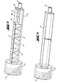
- the static mixer comprises a jacket tube 1 with an inlet opening 2, through which the components of the multi-component compositions are introduced into the static mixer and mixed there, and an outlet opening 3 for the mix.
- the jacket tube 1 at least one mixing section 4 is provided in which one or more mixing elements 5 are provided, which are adapted in their outer dimensions to the inner dimensions of the jacket tube.
- at least one chamber 6 is provided in the jacket tube, in which the additives to be introduced into the mix are arranged.
- the chamber 6 can be arranged in the conveying direction before or after the mixing section 4 or between two mixing sections 4.
- the jacket tube 1 may have a circular, oval and / or angular, preferably circular and / or square inner cross section, wherein the outer cross section may be formed as desired. Furthermore, the defined by the jacket tube 1 interior can be cylindrically shaped, that is, the cross-sectional area is the same in all areas. On the other hand, it is also possible that the cross-sectional area of the jacket tube increases or decreases from the inlet opening to the outlet opening, but preferably decreases, that is, the jacket tube 1 narrows from the inlet opening 2 to the outlet opening third
- the at least one chamber 6 for receiving the introduced into the mix additives 7 at its inlet end or its outlet end by at least one matched in their outer dimensions to the inner dimensions of the casing tube 1 demarcation. This delimitation should be permeable to the mix, but withhold the added to the mix but not yet dissolved or not dispersed in the mix additives 7.
- the at least one chamber 6 is delimited by two delimitations 8 and 9.
- delimitations 8 or 9 may be in the form of a sieve, a perforated plate, a sintered plate and / or a fleece or filter material, for example in the form of a filter bag, these delimitations being arbitrary Materials can be made, for example, paper, metal, glass and / or plastic.
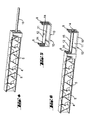
- the embodiment of the static mixer according to the invention shown in Figures 2 to 6 has a square casing tube 1 with square inner and outer cross-section.
- the jacket tube has an inlet opening 2 and an outlet opening 3, wherein at the inlet opening 2 of the jacket tube, a plug connection, screw connection, clamp connection and / or bayonet connection, preferably a thread, is provided for releasably securing the jacket tube to the outlet opening of the components of the liquid , reactive multi-component composition in separate storage containers containing, not shown in the drawing, Auspreß réelles.
- the connector, screw, clamp connection and / or bayonet connection or the thread 17 may be provided with a suitable seal, which prevents the escape of the mix at the junction.
- FIG. 2 shows the mixing element 5 arranged in the mixing section of the jacket tube in a dashed representation and a container 13 present in the chamber 6 for receiving the additives 7 to be introduced into the mix, this container likewise being shown in dashed lines.
- FIG. 3 shows a schematic representation of the jacket tube 1 of this embodiment of the static mixer with the inlet opening 2 and the thread 17 present there as well as the outlet opening 3.
- FIG. 4 shows the mixing element 5 taken out of the jacket tube 1, wherein the shape of the mixing element known per se corresponds to that of a Kenics mixer known per se.
- the mixing element 5 has at one end the centering mandrel 15, for centering the container 13 shown in Figure 5 for receiving the introduced into the mix, not shown additives 7.
- This container 13 is formed from the boundaries 8 and 9, for the Mixtures are permeable, but retains the introduced into the mix but not yet dissolved or dispersed additives 7.
- the boundaries 8 and 9 are at one to the inner dimensions the chamber 6 adapted longitudinal beams 10 attached.
- this side rail 10 has side walls 11 and 12 and in this way forms an upwardly open container 13 for receiving the additives to be introduced into the mix 7.
- the boundaries 8 and 9 have openings 14 which make it possible Move container on the centering pin 15 on the mixing element 5.
- the inner diameter of the openings 14 is adapted to the outer diameter of the centering mandrel 15 that a penetration of the mixed material between the inner edge of the openings 14 and the outer periphery of the centering mandrel 15 is largely prevented.
- the container 13 shown in FIG. 5 is charged with the additives 7 to be introduced into the mix, pushed onto the centering pin 15 and the combination of the mixing part 5 and the container 13 shown in FIG introduced in Figure 3 jacket tube 1.
- the combination formed in this manner is then threaded over the thread 17 at the exit port of a squeezing device containing the components of the multi-component liquid reactive compositions in separate reservoirs and secured in such a manner as to prevent leakage of the mixture at the point of connection.
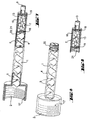
- the static mixer comprises a cylindrical shaped jacket tube 1 with a circular cross-section, which is provided at its inlet opening 2 with a thread 17, for fixing the jacket tube to a squeezing device, as already above has been addressed.
- the mixing section 4 is the mixing element 5, which is shown in dashed lines.
- the chamber 6 is in the form of a releasably connected to the adjacent casing tube 1 and the outlet opening 3 casing pipe piece 16. As shown in FIG. 7, the additives 7 are arranged in this casing pipe section 16.
- the casing pipe section 16 is adapted in its inner cross-section and its cross-sectional surface profile to the circular, oval and / or angular, preferably circular and / or square inner cross-section and the cross-sectional profile of the jacket tube 1.
- the casing pipe piece 16 is also cylindrical and has a circular cross-section which corresponds to that of the casing tube 1.
- the casing pipe piece 16 is fixedly connected to the outlet opening 3 and releasably connected to the casing tube 1, in particular via the threaded connection 20, 21 on the casing tube 1 or the casing pipe piece 16.
- casing pipe section 16 and outlet opening 3 integrally formed, preferably in the form of a molded plastic part, which has been produced for example by injection molding and can be connected via the thread 21 with the jacket tube 1.
- removable separations 18, 19 are provided between the casing pipe section 16 and the casing pipe 1 or before the outlet opening 3, preferably in the form of screens, perforated plates and / or sintered plates made of paper, metal, plastic and / or glass or in the form of a non-woven or Filter material, such as a filter bag.
- the at least one mixing element 5, the container 13 and the boundaries 8, 9, 18, 19 secured against rotation and displacement in the conveying direction for example by the configuration of the inner cross section of the jacket tube, or the outer cross section of the mixing elements 5, the boundaries 8, 9, 18, 19 and the container 13, by grooves in the inner surface of the jacket tube and corresponding lugs of the mixing elements 5, the boundaries 8, 9, 18, 19 and the container 13th
- the boundaries 8, 9, 18, 19 such sized openings that the mix can penetrate, but are retained in the mix to be introduced but not yet dissolved or dispersed additives.
- these openings which are in the form of holes, screen openings, sintering openings, pores or the like, dimensions corresponding to a diameter of 0.2 mm to 2.0 mm, preferably 1 mm to 1.5 mm.
- At least one mixing element 5 is arranged in the at least one chamber 6 or the casing pipe piece 16, which carries on at least one of its surfaces the additives 7 to be introduced into the mix, or is formed from these additives 7.
- this mixing element of a catalytically active material which catalyzes and accelerates the reaction of the reacting mixture formed from the liquid, reactive components of the multi-component compositions. In this way, it is achieved that while the passage material has a sufficiently low viscosity for the passage through the static mixer, but on exit from the outlet opening 3 has a viscosity which prevents the material from flowing down after being applied to ceilings or walls ,
- the mixing elements 5 are shaped to effect mixing of the constituents of the mix by utilizing the flow energy of the components of the liquid reactive multi-component composition introduced under pressure into the static mixer.
- the mixing elements 5 are secured against rotation in the jacket tube 1, for example by grooves in the inner wall of the jacket tube and corresponding lugs on the outside of the mixing elements fifth
- the jacket tube of the static mixer according to the invention can also have a plug-in connection, screw connection, clamping connection and / or bayonet connection preventing the outlet of the mixture at the connection point, but preferably a thread with which the jacket tube can be fastened to the outlet opening of a squeezing device which contains the components of the liquid, reactive multicomponent composition in separate storage containers. This is done after arranging the introduced into the mix additives 7 in the chamber 6. The choice of type and amount of these additives depending on the ongoing reaction between the liquid, reactive components of the multi-component composition and the resulting in the static mixer formed Mischguts and the desired properties of the emerging from the outlet opening 3 of the static mixer mixed material.
- Another object of the invention relates to the use of the static mixer described above for the introduction of additives in the mix, which are suitable for modifying the physical and / or chemical properties of the liquid mixture formed from the liquid, reactive multi-component composition.
- additives which increase the viscosity of the mix.
- the static mixer according to the invention is used to increase the viscosity of a liquid fire-resistant foam produced in the at least one mixing section 4 and not yet fully reacted.
- the static mixer according to the invention for the speed of the polyurethane formation and the foaming process to introduce an additive from the liquid, reactive multi-component composition formed liquid polyurethane foam system additives in the mix and mix it homogeneously.
Landscapes
- Chemical & Material Sciences (AREA)
- Chemical Kinetics & Catalysis (AREA)
- Dispersion Chemistry (AREA)
- Engineering & Computer Science (AREA)
- Mechanical Engineering (AREA)
- Processing And Handling Of Plastics And Other Materials For Molding In General (AREA)
- Preparation Of Compounds By Using Micro-Organisms (AREA)
Abstract
Description
Gegenstand der vorliegenden Erfindung sind ein statischer Mischer zum Vermischen der Komponenten von flüssigen, reaktiven Mehrkomponenten-Zusammensetzungen, mit einem mindestens einen Mischabschnitt definierenden Mantelrohr, mit Eintrittsöffnung und Austrittsöffnung für das Mischgut, und mindestens einem in dem Mischabschnitt angeordneten, in seinen Außenabmessungen an die Innenabmessungen des Mantelrohrs angepaßten Mischelement, sowie die Verwendung dieses statischen Mischers zur Einführung von die physikalischen und/oder chemischen Eigenschaften des aus der flüssigen, reaktiven Mehrkomponenten-Zusammensetzung gebildeten flüssigen Mischguts beeinflussenden Zusatzstoffen.The present invention relates to a static mixer for mixing the components of liquid, reactive multi-component compositions, with a jacket tube defining at least one mixing section, with inlet opening and outlet opening for the mix, and at least one arranged in the mixing section, in its outer dimensions to the inner dimensions the jacket tube adapted mixing element, and the use of this static mixer for the introduction of the physical and / or chemical properties of the liquid mixture formed from the liquid, reactive multi-component composition influencing additives.
Flüssige, reaktive Mehrkomponenten-Zusammensetzungen werden in vielfältiger Weise eingesetzt, beispielsweise als Zweikomponenten-Klebstoffe, Zweikomponenten-Mörtelmassen zur Befestigung von Bauteilen, Ankerstangen und dergleichen in festen Untergründen, wie Mauerwerk, Beton oder sonstigen harten Unterlagen oder zur Bildung von Brandschutzschäumen oder Konstruktionsschäumen, die zum Ausfüllen von Durchbrüchen, Durchführungen und Öffnungen in Wänden, Decken und Böden von Gebäuden oder aber auch zum Einbau von Fenstern und Türen in Gebäuden. Solche Mehrkomponenten-Zusammensetzungen, namentlich solche, die für diese Zwecke auf Baustellen vor Ort eingesetzt werden, liegen normalerweise in Mehrkammer-Behältern oder -Beuteln vor, in denen die miteinander reagierenden Komponenten reaktionsinhibierend voneinander getrennt gelagert sind. Bei der bestimmungsgemäßen Anwendung werden die verschiedenen Komponenten aus den getrennten Behältern ausgebracht, beispielsweise durch Auspressen mit Hilfe eines Auspreßgerätes, und dann vermischt, wonach dann das erhaltene Mischgut auf den Anwendungsbereich aufgebracht, beispielsweise in ein Dübelloch eingeführt wird.Liquid, reactive multi-component compositions are used in a variety of ways, for example as two-component adhesives, two-component mortar compositions for attachment of components, anchor rods and the like in solid substrates, such as masonry, concrete or other hard documents or for the formation of fire protection foams or structural foams to fill openings, ducts and openings in walls, ceilings and floors of buildings or else to install windows and doors in buildings. Such multicomponent compositions, especially those which are used on site for these purposes on construction sites, are normally present in multi-chamber containers or bags, in which the mutually reactive components are stored separately from one another in a reaction-inhibiting manner. In the intended use, the various components are discharged from the separate containers, for example by pressing with the aid of a squeezing, and then mixed, after which the resulting mix is applied to the application, for example, introduced into a dowel hole.
Anschließend werden die zu befestigenden Bauteile aufgebracht, beispielsweise die Ankerstange, in das mit dem Mischgut beschickte Dübelloch eingebracht, in dem die Aushärtung der Zusammensetzung erfolgt, die bereits nach dem Vermischen der Komponenten des Mischguts einsetzt.Subsequently, the components to be fastened are applied, for example, the anchor rod, introduced into the dowel hole charged with the mix, in which the curing of the composition takes place, which already starts after mixing the components of the mix.
Im Bereich der thermischen Isolierung von Gebäuden werden weiterhin Dosiermaschinen verwendet, um großflächig Isolierschäume auf Wände und Decken aufzusprühen. Hierzu werden im vorderen Bereich der Sprühpistolen Aufsätze aufgebracht, mit denen die einzelnen Komponenten der Mehrkomponenten-Isolierschaumzusammensetzungen vermischt werden.In the field of thermal insulation of buildings dosing machines continue to be used to spray insulation foams on walls and ceilings over a large area. For this purpose, attachments are applied in the front region of the spray guns, with which the individual components of the multicomponent insulating foam compositions are mixed.
Für das Vermischen der verschiedenen Komponenten der Zusammensetzungen werden üblicherweise statische Mischer oder Statikmischer eingesetzt, die in einem Mantelrohr ein Mischelement enthalten, welches ein homogenes Vermischen der Bestandteile des Mischgutes unter Nutzung der Strömungsenergie der unter Druck in den statischen Mischer eingebrachten Komponenten der Mehrkomponenten-Zusammensetzungen bewirkt. Es handelt sich dabei um Mischeinrichtungen, die weder einen bewegten Behälter noch bewegte Mischwerkzeuge aufweisen, bei denen das Durchmischen des Mischgutes lediglich unter der Einwirkung der Bewegungsenergie des Mischgutes erfolgt, welches kontinuierlich durch den statischen Mischer geführt wird und aufgrund der in dem Strömungsverlauf vorliegenden Mischelemente eine intensive Durchmischung des Mischgutes bewirkt. Solche Mischelemente sind Krümmer, Erweiterungen, Injektoren, Gegenstromstrahlen, Drallapparate, Leitbleche oder Einbauten verschiedenster Art, die durch ihre geometrische Ausbildung zu einer intensiven Quervermischung des Mischgutes führen.For mixing the various components of the compositions, static mixers or static mixers are usually used, which in a jacket tube contain a mixing element which effects homogeneous mixing of the constituents of the mixed material using the flow energy of the components of the multi-component compositions introduced under pressure into the static mixer , These are mixing devices which have neither a moving container nor moving mixing tools, in which the mixing of the mixed material takes place only under the effect of the kinetic energy of the mixed material, which is continuously passed through the static mixer and due to the mixing elements present in the flow intensive mixing of the mix causes. Such mixing elements are manifolds, extensions, injectors, countercurrent jets, twisting devices, baffles or internals of various kinds, which lead by their geometric design to intensive cross-mixing of the mix.
Sowohl das Mantelrohr als auch die Mischelemente solcher statischer Mischer können aus den unterschiedlichsten Materialien bestehen, beispielsweise aus Metall, Glas und insbesondere Kunststoff, wobei insbesondere die für das Vermischen und Ausbringen von Mehrkomponenten-Zusammensetzungen in Form von Mörtelmassen, Bauschäumen etc. eingesetzten statischen Mischer aus Kunststoff bestehen, mit herausnehmbaren Mischelementen unterschiedlichster Ausgestaltung.Both the jacket tube and the mixing elements of such static mixers can be made of a wide variety of materials, for example metal, glass and in particular plastic, wherein in particular the static mixers used for mixing and dispensing of multi-component compositions in the form of mortar compounds, building materials, etc. Plastic consist, with removable mixing elements of different design.
Die für das Durchmischen von Mehrkomponenten-Zusammensetzungen, die als Mörtelmassen, Bauschäume, Brandschutzschäume etc. vor Ort auf der Baustelle eingesetzten Mischer liegen im allgemeinen in Form von einmal benutzten, wegwerfbaren Kunststoffstatikmischern vor, in Form eines Mantelrohrs und darin vorliegenden Mischelementen, die auf die Austrittsöffnung des Auspreßgerätes aufgesetzt und dort fixiert werden. Aus dem Auspreßgerät werden die in getrennten Behältern vorliegenden Bestandteile der Mehrkomponenten-Zusammensetzung unter Druckeinwirkung, sei es durch mechanischen Auspreßdruck oder unter Einsatz eines Druckfluids oder eines Treibmittels, aus den getrennten Vorratsbehältern ausgepresst und durch den aufgesetzten statischen Mischer hindurchgeführt.The mixers used for the mixing of multicomponent compositions used as mortar masses, construction foams, fire protection foams etc. on site at the construction site are generally in the form of disposable plastic static mixers used once, in the form of a jacket tube and mixing elements present therein Outlet opening of the Auspreßgerätes placed and fixed there. From the Auspreßgerät be present in separate containers components of the multi-component composition under pressure, be it by mechanical squeezing pressure or by using a pressurized fluid or a propellant, squeezed out of the separate storage containers and passed through the attached static mixer.
Bei der Anwendung solcher Mehrkomponenten-Zusammensetzungen auf der Baustelle, beispielsweise an Wänden und Decken, besteht nun häufig das Problem, daß das aus dem Mundstück des statischen Mischers austretende Mischgut, in dem die Aushärtungs- und/oder Aufschäumreaktionen ablaufen, nach dem Aufbringen auf den Bestimmungsort, beispielsweise an der Decke oder an senkrechten Wänden, noch keine ausreichende Viskosität aufweist und aus den zu verschließenden Öffnungen heraus- und an den Wänden herunterfließt. Gewöhnlich wird daher üblicherweise eine Schalung aus Pappkarton verwendet, die mit Klebeband an der Unterseite der Decke oder der Wand befestigt wird, um dieses Ausfließen der ausreagierenden Zusammensetzung zu verhindern. Im Bereich von Öffnungen in Trockenbauwänden werden auch Schalungen aus feinem Drahtgeflecht oder Streckmetall eingesetzt, die für die jeweilige Öffnung passend zurechtgebogen werden. Es ist ersichtlich, daß das Anbringen einer Schalung zur Verhinderung des Abfließens der reagierenden Mehrkomponenten-Zusammensetzung einen zusätzlichen Arbeitsschritt und damit höhere Kosten mit sich bringt.When applying such multi-component compositions on the construction site, for example on walls and ceilings, there is now often the problem that the emerging from the mouthpiece of the static mixer mix in which run the curing and / or Aufschäumreaktionen after application to the Destination, for example, on the ceiling or on vertical walls, not yet having sufficient viscosity and out of the openings to be closed and runs down the walls. Usually, therefore, a formwork of cardboard is used, which is adhesively attached to the underside of the ceiling or the wall to prevent this outflow of the ausreagierenden composition. In the area of openings in drywall walls also formworks made of fine wire mesh or expanded metal are used, which are bent suitable for the respective opening. It can be seen that the provision of a form to prevent the outflow of the reacting multi-component composition brings an additional step and thus higher costs.
Weiterhin ist es bekannt, daß solche Mörtelmassen und insbesondere Schäume durch chemische oder physikalische Thixotropiermittel so modifiziert werden können, daß sie auch in nicht vollständig ausreagiertem Zustand eine ausreichende "Standfestigkeit" aufweisen. Durch die Anwendung von solchen thixotropierenden Mittel lassen sich zwar füllstoffreie Isolierschäume niedriger Dichte standfest einstellen. Bei hochgefüllten Brandschutzschäumen mit hoher Dichte führt die Viskositätserhöhung durch die Thixotropiermittel zu Problemen beim Auspressen der Komponenten durch den erhöhten Fließwiderstand.Furthermore, it is known that such mortar compositions and in particular foams can be modified by chemical or physical thixotropic agents so that they have a sufficient "stability" even when not fully reacted. Through the use of such thixotropic agents, filler-free insulating foams of low density can be set steadily. For highly filled, high density fire protection foams, the increase in viscosity due to the thixotropic agents leads to problems when extruding the components due to the increased flow resistance.
Es hat sich weiterhin gezeigt, daß man die Standfestigkeit von Zweikomponenten-Poyurethan-Schäumen, die als solche Bauschäume eingesetzt werden können, dadurch erhöhen kann, daß man zusätzlich Acrylat in das Mischgut einbringt. Diese Viskositätserhöhung wird erreicht durch einen der Polyurethan-Bildungsreaktionen vorgelagerten physikalischen Effekt, nämlich des Brechens der Acrylatdispersion in dem Mischgut durch den Polaritätsunterschied des Isocyanats zu der ersten Komponente. Dies führt zu einer Vergelung und damit zu einer Erhöhung der Viskosität des Mischgutes.It has also been shown that one can increase the stability of two-component Poyurethan foams that can be used as such construction foam, thereby introducing additional acrylate in the mix. This increase in viscosity is achieved by a physical effect upstream of the polyurethane formation reactions, namely the Breaking the acrylate dispersion in the mix by the polarity difference of the isocyanate to the first component. This leads to a gelling and thus to an increase in the viscosity of the mix.
Der Vorteil eines solchen Brechens der Acrylatdispersion ist der, daß das Mischgut beim Eintritt in den statischen Mischer eine geringe Viskosität aufweist, welche dann beim Hindurchtreten durch den statischen Mischer langsam ansteigt, was zur Folge hat, daß der Anwender nur geringe Kräfte aufbieten muß, um das Mischgut aus dem statischen Mischer auszupressen. Wenn der Schaum aus dem statischen Mischer austritt, besitzt er eine ausreichend hohe Klebrigkeit, um an der Wand anzuhaften, weist jedoch eine Viskosität auf, die ein Herausfließen des Mischgutes aus den Öffnungen beziehungsweise ein Herunterfließen an der Wand zu verhindert.The advantage of such breakage of the acrylate dispersion is that the mix, on entering the static mixer, has a low viscosity, which then slowly increases as it passes through the static mixer, with the result that the operator only has to exert small forces to squeeze the mix out of the static mixer. When the foam exits the static mixer, it has a sufficiently high tack to adhere to the wall, but has a viscosity which prevents the mixture from flowing out of the openings or flowing down the wall.
Der Nachteil des oben angesprochenen Effektes des Brechens der Acrylatdispersion in einer Zweikomponenten-Polyurethan/Acrylat-Schaumzusammensetzung ist die Temperaturabhängigkeit der nachgelagerten Polyurethanreaktion. Bei hohen Anwendungstemperaturen oberhalb 25°C, die man beispielsweise im Sommer auf der Baustelle antrifft, besteht die Gefahr, daß die Polyurethanbildungsreaktion schneller abläuft als das Brechen der Acrylatdispersion unter Erhöhung der Viskosität, so daß der angestrebte Effekt des Verhinderns des Herabfließens des Mischgutes nicht erreicht wird. Dies hat zur Folge, daß der erwünschte physikalische Dispersionsbruch unterdrückt wird und daß die angestrebten physikalischen Eigenschaften des ausgehärteten Schaumes nicht erreicht werden, beispielsweise durch eine geringe Dichte des ausgehärteten Materials. Zwar ist es möglich, die Geschwindigkeit des Dispersionsbruches durch geeignete Zusätze in der Polyolkomponente und in der Polyisocyanatkomponente und durch die Mischgüte des statischen Mischers zu variieren. Allerdings sind der Geschwindigkeitserhöhung des Brechens der Dispersion aber Grenzen gesetzt durch die physikalische Länge des Mischers. Für den Fall, daß das Brechen der Dispersion zu schnell stattfindet, ergibt sich ein Ausfällen der Dispersion in dem statischen Mischer, was zur Folge hat, daß der Anwender zu hohe Kräfte aufbringen muß, um das Mischgut aus dem statischen Mischer auszubringen.The disadvantage of the above-mentioned effect of breaking the acrylate dispersion in a two-part polyurethane / acrylate foam composition is the temperature dependence of the downstream polyurethane reaction. At high application temperatures above 25 ° C, which occurs for example in the summer on the site, there is a risk that the polyurethane formation reaction proceeds faster than the breaking of the acrylate dispersion with increase in viscosity, so that the desired effect of preventing the downflow of the mix does not reach becomes. This has the consequence that the desired physical dispersion fracture is suppressed and that the desired physical properties of the cured foam are not achieved, for example by a low density of the cured material. Although it is possible to vary the speed of dispersion breakage by suitable additives in the polyol component and in the polyisocyanate component and by the mixing quality of the static mixer. However, the speed increase of the breaking of the dispersion is limited by the physical length of the mixer. In the event that the breakage of the dispersion takes place too rapidly, the precipitation of the dispersion in the static mixer results, with the result that the user must apply excessive forces in order to discharge the mix from the static mixer.
Die der vorliegenden Erfindung zugrundeliegende Aufgabe besteht nun darin, einen statischen Mischer bereitzustellen, mit dem es gelingt, dem aus der flüssigen, reaktiven Mehrkomponenten-Zusammensetzung gebildeten flüssigen Mischgut Zusatzstoffe zuzuführen, mit denen die physikalischen und/oder chemischen Eigenschaften dieses Mischguts gezielt beeinflußt werden können in der Weise, daß die angestrebten Eigenschaften erst nach dem Austritt aus dem Mischer erreicht werden und dadurch ein leichtes Auspressen des Mischgutes aus dem statischen Mischer möglich wird.The object underlying the present invention is now to provide a static mixer, with which it is possible from the liquid mix formed liquid liquid reactive additives, with which the physical and / or chemical properties of this mixture can be selectively influenced in such a way that the desired properties are achieved only after exiting the mixer and thereby a slight squeezing of the Mixing material from the static mixer is possible.
Gleichzeitig soll durch ein gutes Durchmischen der Zusatzstoffe mit dem Mischgut eine schnelle Beeinflussung der physikalischen und/oder chemischen Eigenschaften des Mischgutes erreicht werden, so daß das Mischgut unmittelbar nach dem Ausbringen des Mischgutes aus der Austrittsöffnung des statischen Mischers die angestrebten physikalischen und/oder chemischen Eigenschaften aufweist. Hierdurch soll erreicht werden, daß beispielsweise ein ausgebrachter Bauschaum eine hohe Klebrigkeit aufweist und damit gut an dem bestimmungsgemäßen Ort anhaftet und eine ausreichend hohe Standfestigkeit aufweist, so daß ein schalungsfreies Auftragen des Schaumes auf der Wand und an der Decke möglich wird. Gleichzeit soll es möglich sein, die zuzuführenden Zuschlagstoffe ohne weiteres vor Ort in Abhängigkeit von den einzuhaltenden Umgebungsbedingungen beziehungsweise den anzustrebenden Eigenschaften des Mischgutes auszuwählen und in den erforderlichen Mengen in das Mischgut einzubringen.At the same time a rapid influence of the physical and / or chemical properties of the mix is to be achieved by a good mixing of the additives with the mix, so that the mix immediately after the application of the mix from the outlet of the static mixer the desired physical and / or chemical properties having. This is intended to ensure that, for example, a spent construction foam has a high tackiness and thus adheres well to the intended location and has a sufficiently high stability, so that a shuttering-free application of the foam on the wall and on the ceiling is possible. At the same time it should be possible to easily select the additives to be supplied on site depending on the environmental conditions to be respected or the desired properties of the mix and bring in the required quantities in the mix.
Es hat sich gezeigt, daß diese Aufgabe dadurch gelöst werden kann, daß man die in das Mischgut einzubringenden Zusatzstoffe vorzugsweise in fester Form in eine in dem Mantelrohr vorgesehene Kammer des statischen Mischers einbringt, die sich vorzugsweise im Bereich in der Nähe der Austrittsöffnung findet. Bei der erfindungsgemäßen Benutzung strömt das durch den statischen Mischer hindurchgeförderte und durchmischte Mischgut an diesen Zusatzstoffen vorbei und nimmt diese unter gleichzeitiger Durchmischung auf, wodurch eine gute Durchmischung der Zusatzstoffe mit dem Mischgut unmittelbar vor der Austrittsöffnung des statischen Mischers erreicht und damit die angestrebten Eigenschaften des aus dem statischen Mischer austretenden Mischgutes erzielt werden.It has been found that this object can be achieved by introducing the introduced into the mix additives preferably in solid form in a provided in the casing tube chamber of the static mixer, which is preferably in the area in the vicinity of the outlet opening. When used according to the invention, the mixed mix conveyed through and mixed through the static mixer flows past these additives and absorbs them with simultaneous mixing, whereby a thorough mixing of the additives with the mix directly before the outlet opening of the static mixer and thus the desired properties of the static mixer escaping mixed material can be achieved.
Gegenstand der Erfindung ist daher der statische Mischer gemäß Hauptanspruch. Die Unteransprüche betreffen bevorzugte Ausführungsformen dieses Erfindungsgegenstandes sowie die Verwendung dieses statischen Mischers zur Einführung von physikalischen und/oder chemischen Eigenschaften des Mischgutes beeinflussenden Zusatzstoffen in dieses Mischgut.The invention is therefore the static mixer according to the main claim. The subclaims relate to preferred embodiments of this subject of the invention as well as the use of this static mixer for the introduction of physical and / or chemical properties of the mix influencing additives in this mix.
Die Erfindung betrifft insbesondere einen statischen Mischer zum Vermischen der Komponenten von flüssigen, reaktiven Mehrkomponenten-Zusammensetzungen, mit einem mindestens einen Mischabschnitt definierenden Mantelrohr, mit Eintrittsöffnung und Austrittsöffnung für das Mischgut, und mindestens einem in dem Mischabschnitt angeordneten, in seinen Außenabmessungen an die Innenabmessungen des Mantelrohrs angepaßten Mischelement, welcher gekennzeichnet ist durch mindestens eine zwischen der Eintrittsöffnung und der Ausgangsöffnung in dem Mantelrohr vorgesehene Kammer zur Aufnahme von in das Mischgut einzubringenden Zusatzstoffen.The invention particularly relates to a static mixer for mixing the components of liquid, reactive multicomponent compositions, with a jacket tube defining at least one mixing section, with inlet opening and outlet opening for the mix, and at least one arranged in the mixing section, in its outer dimensions to the inner dimensions of Jacket tube adapted mixing element, which is characterized by at least one provided between the inlet opening and the outlet opening in the jacket tube chamber for receiving introduced into the mix additives.
Bei diesen Zusatzstoffen handelt es sich beispielsweise um an sich bekannte Produkte, welche die Viskosität des durch den statischen Mischer strömenden Mischgutes erhöhen und eine Gelbildung verursachen. Beispielsweise kommen als solche Dispersionen brechende Mittel Salze oder den pH-Wert erhöhende chemische Stoffe in Frage, die sich relativ leicht in dem Mischgut lösen oder dispergieren. Als Zusatzstoffe können auch Polymerisationsbeschleuniger, Thixotropiermittel, Ausfällungsmittel, verflüssigende Mittel und dergleichen eingesetzt werden. Weiterhin ist es möglich, als Zusatzstoffe dieser Art Katalysatoren für die in dem Mischgut ablaufenden Reaktionen zu verwenden.These additives are, for example, known per se products which increase the viscosity of the mixture flowing through the static mixer and cause gelation. For example, salts or pH-increasing chemical substances which dissolve or disperse relatively easily in the mix are suitable as such dispersants. As additives, polymerization accelerators, thixotropic agents, precipitating agents, liquefying agents and the like can also be used. Furthermore, it is possible to use as additives of this type catalysts for the running in the mix reactions.
Das Ausmaß der Veränderung der physikalischen und/oder chemischen Eigenschaften beziehungsweise der Reaktionsbedingungen des reagierenden Mischgutes wird durch die Art, die Menge und die Teilchengröße der vorzugsweise festen Zusatzstoffe gesteuert, die in der in dem Mantelrohr vorgesehenen Kammer vorliegen und die sich im Zuge des Hindurchführens des Mischgutes in diesem lösen oder dispergieren, während die nicht gelösten oder nicht dispergierten Zusatzstoffe in der Kammer zurückgehalten werden.The extent of the change in the physical and / or chemical properties or the reaction conditions of the reacting mixed material is controlled by the type, the amount and the particle size of the preferably solid additives which are present in the chamber provided in the jacket tube and in the course of passing the Mix or disperse mixed material in it, while the undissolved or undispersed additives are retained in the chamber.
Da es mit Hilfe des erfindungsgemäßen statischen Mischers möglich ist, die in das Mischgut einzubringenden Zusatzstoffe an beliebigen Stellen des statischen Mischers einzubringen, wird es möglich, die angestrebte Veränderung der physikalischen und/oder chemischen Eigenschaften des Mischgutes in der Weise zu steuern, daß das Mischgut nach dem Austreten aus der Austrittsöffnung des statischen Mischers die angestrebten Eigenschaften aufweist.Since it is possible with the aid of the static mixer according to the invention to introduce the introduced into the mix additives at any point of the static mixer, it is possible to control the desired change in the physical and / or chemical properties of the mix in such a way that the mix after exiting the exit opening the static mixer has the desired properties.
Die Erfindung sei im folgenden näher unter Bezugnahme auf die beigefügten Zeichnungen erläutert.The invention will be explained in more detail below with reference to the accompanying drawings.
In den Zeichnungen zeigen:
- Figur 1:
- Eine schematische Darstellung des erfindungsgemäßen statischen Mischers;
- Figur 2:
- eine perspektivische Darstellung einer ersten bevorzugten Ausführungsform des erfindungsgemäßen statischen Mischers in zusammengefügtem Zustand, wobei in dem die innerhalb des Mantelrohrs liegenden Mischelemente und die Bestandteile der Kammer gestrichelt wiedergegeben sind;
- Figur 3:
- eine perspektivische Darstellung des Mantelrohrs dieser Ausführungsform des erfindungsgemäßen statischen Mischers;
- Figur 4:
- eine perspektivische Darstellung des Mischelements dieser Ausführungsform des statischen Mischers;
- Figur 5:
- eine perspektivische Darstellung eines in die Kammer einzubringenden Behälters zur Aufnahme der in das Mischgut einzubringenden Zusatzstoffe;
- Figur 6:
- eine perspektivische Darstellung der zusammengefügten Kombination aus dem Mischelement und diesem Behälter zur Aufnahme der Zusatzstoffe;
- Figur 7:
- eine perspektivische Darstellung einer weiteren bevorzugten Ausführungsform des erfindungsgemäßen statischen Mischers in zusammengebautem Zustand, wobei die innenliegenden Mischelemente und die Zusatzstoffe gestrichelt wiedergegeben sind;
- Figur 8:
- eine perspektivische Teildarstellung dieser Ausführungsform des erfindungsgemäßen statischen Mischers ohne die abgenommene Kammer zur Aufnahme der in das Mischgut einzubringenden Zusatzstoffe; und
- Figur 9:
- eine perspektivische Darstellung dieser abgenommenen Kammer zur Aufnahme der Zusatzstoffe.
- FIG. 1:
- A schematic representation of the static mixer according to the invention;
- FIG. 2:
- a perspective view of a first preferred embodiment of the static mixer according to the invention in an assembled state, in which the mixing elements lying within the jacket tube and the components of the chamber are shown in dashed lines;
- FIG. 3:
- a perspective view of the jacket tube of this embodiment of the static mixer according to the invention;
- FIG. 4:
- a perspective view of the mixing element of this embodiment of the static mixer;
- FIG. 5:
- a perspective view of a container to be introduced into the chamber for receiving the additives to be introduced into the mix;
- FIG. 6:
- a perspective view of the assembled combination of the mixing element and this container for receiving the additives;
- FIG. 7:
- a perspective view of another preferred embodiment of the static mixer according to the invention in the assembled state, wherein the internal mixing elements and the additives are shown in dashed lines;
- FIG. 8:
- a partial perspective view of this embodiment of the static mixer according to the invention without the removed chamber for receiving the introduced into the mix additives; and
- FIG. 9:
- a perspective view of this removed chamber for receiving the additives.
Wie aus der Figur 1 hervorgeht, umfaßt der erfindungsgemäße statische Mischer ein Mantelrohr 1 mit einer Eintrittsöffnung 2, durch welche die Bestandteile der Mehrkomponenten-Zusammensetzungen in den statischen Mischer eingeführt und dort durchmischt werden, und einer Austrittsöffnung 3 für das Mischgut. In dem Mantelrohr 1 ist mindestens ein Mischabschnitt 4 vorgesehen in dem ein oder mehrere Mischelemente 5 vorgesehen sind, die in ihren Außenabmessungen an die Innenabmessungen des Mantelrohrs angepaßt sind. Zwischen der Eintrittsöffnung 2 und der Austrittsöffnung 3 ist mindestens eine Kammer 6 in dem Mantelrohr vorgesehen, in der die in das Mischgut einzubringenden Zusatzstoffe angeordnet werden.As is apparent from Figure 1, the static mixer according to the invention comprises a
Die Kammer 6 kann in Förderrichtung vor oder nach dem Mischabschnitt 4 oder zwischen zwei Mischabschnitten 4 angeordnet sein.The
Das Mantelrohr 1 kann einen kreisförmigen, ovalen und/oder eckigen, vorzugsweise kreisförmigen und/oder quadratischen Innenquerschnitt aufweisen, wobei der Außenquerschnitt beliebig ausgebildet sein kann. Weiterhin kann der durch das Mantelrohr 1 definierte Innenraum zylindrisch geformt sein, das heißt die Querschnittsfläche ist in allen Bereichen die gleiche. Anderseits ist es auch möglich, daß die Querschnittsfläche des Mantelrohres von der Eintrittsöffnung zur Austrittsöffnung zunimmt oder abnimmt, vorzugsweise nimmt sie jedoch ab, das heißt das Mantelrohr 1 verengt sich von der Eintrittsöffnung 2 zur Austrittsöffnung 3.The
Gemäß einer bevorzugten Ausführungsform kann die mindestens eine Kammer 6 zur Aufnahme der in das Mischgut einzubringenden Zusatzstoffe 7 an ihrem Einlaufende beziehungsweise ihrem Auslaufende durch mindestens eine in ihren Außenabmessungen an die Innenabmessungen des Mantelrohrs 1 angepaßte Abgrenzung aufweisen. Diese Abgrenzung soll für das Mischgut durchlässig sein, jedoch die in das Mischgut einzubringenden aber noch nicht gelösten oder nicht in dem Mischgut dispergierten Zusatzstoffe 7 zurückhalten. Gemäß einer bevorzugten Ausführungsform wird die mindestens eine Kammer 6 durch zwei Abgrenzungen 8 und 9 begrenzt. Diese Abgrenzungen 8 beziehungsweise 9 können in Form eines Siebes, einer Lochplatte, einer Sinterplatte und/oder eines Vlies- oder Filtermaterials, beispielsweise in Form eines Filterbeutels, vorliegen, wobei diese Abgrenzungen aus beliebigen Materialien gefertigt sein können, beispielsweise aus Papier, Metall, Glas und/oder Kunststoff.According to a preferred embodiment, the at least one
Die in den Figuren 2 bis 6 dargestellte Ausführungsform des erfindungsgemäßen statischen Mischers weist ein quadratisches Mantelrohr 1 mit quadratischem Innen- und Außenquerschnitt auf. Das Mantelrohr weist eine Eintrittsöffnung 2 und eine Austrittsöffnung 3 auf, wobei an der Eintrittsöffnung 2 des Mantelrohrs eine Steckverbindung, Schraubverbindung, Klemmverbindung und/oder Bayonettverbindung, vorzugsweise ein Gewinde, vorgesehen ist, zur lösbaren Befestigung des Mantelrohrs an der Austrittsöffnung eines die Komponenten der flüssigen, reaktiven Mehrkomponenten-Zusammensetzung in getrennten Vorratsbehältern enthaltenden, in der Zeichnung nicht dargestellten Auspreßgeräts. Dabei kann die Steckverbindung, Schraubverbindung, Klemmverbindung und/oder Bayonettverbindung oder auch das Gewinde 17 mit einer geeigneten Dichtung versehen sein, die das Austreten des Mischguts an der Verbindungsstelle verhindert.The embodiment of the static mixer according to the invention shown in Figures 2 to 6 has a
Die Figur 2 zeigt dabei das in dem Mischabschnitt des Mantelrohrs angeordnete Mischelement 5 in gestrichelter Darstellung sowie einen in der Kammer 6 vorliegenden Behälter 13 zur Aufnahme der in das Mischgut einzubringenden Zusatzstoffe 7, wobei dieser Behälter ebenfalls gestrichelt wiedergegeben ist.FIG. 2 shows the mixing
Die Figur 3 zeigt eine schematische Darstellung des Mantelrohrs 1 dieser Ausführungsform des statischen Mischers mit der Eintrittsöffnung 2 und dem dort vorliegenden Gewinde 17 sowie der Austrittsöffnung 3.FIG. 3 shows a schematic representation of the
In der Figur 4 ist das aus dem Mantelrohr 1 herausgenommene Mischelement 5 wiedergegeben, wobei die Ausformung des an sich bekannten Mischelements derjenigen eines an sich bekannten Kenics-Mischers entspricht. Das Mischelement 5 weist an einem Ende den Zentrierdorn 15 auf, zum Zentrieren des in der Figur 5 dargestellten Behälters 13 zur Aufnahme der in das Mischgut einzubringenden, nicht dargestellten Zusatzstoffe 7. Dieser Behälter 13 ist aus den Abgrenzungen 8 und 9 gebildet, die für das Mischgut durchlässig sind, jedoch die in das Mischgut einzubringenden aber noch nicht gelösten oder dispergierten Zusatzstoffe 7 zurückhält. Gemäß dieser bevorzugten Ausführungsform sind die Abgrenzungen 8 und 9 an einem an die Innenabmessungen der Kammer 6 angepaßten Längsträger 10 befestigt. Weiterhin weist dieser Längsträger 10 Seitenwangen 11 und 12 auf und bildet in dieser Weise einen nach oben offenen Behälter 13 zur Aufnahme der in das Mischgut einzubringenden Zusatzstoffe 7. Bei dieser bevorzugten Ausführungsform weisen die Abgrenzungen 8 und 9 Öffnungen 14 auf, die es ermöglichen, den Behälter über den Zentrierdorn 15 auf das Mischelement 5 aufzuschieben. Dabei ist der Innendurchmesser der Öffnungen 14 derart an den Außendurchmesser des Zentrierdorns 15 angepaßt, daß ein Hindurchdringen des Mischgutes zwischen der Innenkante der Öffnungen 14 und dem Außenumfang des Zentrierdornes 15 weitgehend verhindert wird.FIG. 4 shows the mixing
Bei der bestimmungsgemäßen Benutzung dieses statischen Mischers wird beispielsweise der in der Figur 5 dargestellte Behälter 13 mit den in das Mischgut einzubringenden Zusatzstoffen 7 beschickt, auf den Zentrierdorn 15 aufgeschoben und die in der Figur 6 dargestellte Kombination aus dem Mischteil 5 und dem Behälter 13 in das in der Figur 3 dargestellte Mantelrohr 1 eingeführt. Die in dieser Weise gebildete Kombination wird dann über das Gewinde 17 an der Austrittsöffnung eines die Komponenten der flüssigen reaktiven Mehrkomponenten-Zusammensetzungen in getrennten Vorratsbehältern enthaltenden Auspreßgeräts aufgeschraubt und in der Weise befestigt, daß ein Austreten des Mischgutes an der Verbindungsstelle verhindert wird.During the intended use of this static mixer, for example, the
Bei der in den Figuren 7 bis 9 dargestellten weiteren Ausführungsform der Erfindung umfaßt der statische Mischer ein zylindrisch geformtes Mantelrohr 1 mit kreisförmigem Querschnitt, welches an seiner Eintrittsöffnung 2 mit einem Gewinde 17 versehen ist, zur Befestigung des Mantelrohrs an einer Auspreßeinrichtung, wie sie oben bereits angesprochen worden ist. In dem Mischabschnitt 4 befindet sich das Mischelement 5, welches gestrichelt wiedergegeben ist. Bei dieser Ausführungsform liegt die Kammer 6 in Form eines lösbar mit dem benachbarten Mantelrohr 1 und der Austrittsöffnung 3 verbundenen Mantelrohrstücks 16 vor. Wie in der Figur 7 dargestellt ist, sind die Zusatzstoffe 7 in diesem Mantelrohrstück 16 angeordnet.In the further embodiment of the invention shown in Figures 7 to 9, the static mixer comprises a cylindrical shaped
Vorzugsweise ist das Mantelrohrstück 16 in seinem Innen-Querschnitt und seinem Querschnittsflächenverlauf an den kreisförmigen, ovalen und/oder eckigen, vorzugsweise kreisförmigen und/oder quadratischen Innen-Querschnitt und den Querschnittsverlauf des Mantelrohrs 1 angepaßt. Bei der in den Figuren 7 bis 9 dargestellten Ausführungsform ist das Mantelrohrstück 16 ebenfalls zylindrisch und weist einen kreisförmigen Querschnitt auf, der demjenigen des Mantelrohrs 1 entspricht.Preferably, the
Gemäß einer weiteren bevorzugten Ausführungsform ist das Mantelrohrstück 16 fest mit der Austrittsöffnung 3 und lösbar mit dem Mantelrohr 1 verbunden, insbesondere über die Gewindeverbindung 20, 21 an dem Mantelrohr 1 beziehungsweise dem Mantelrohrstück 16. Einer weiteren bevorzugten Ausführungsform der Erfindung zufolge sind Mantelrohrstück 16 und Austrittsöffnung 3 einstückig ausgebildet, vorzugsweise in Form eines Kunststofformteils, welches beispielsweise durch Spritzguß hergestellt worden ist und über das Gewinde 21 mit dem Mantelrohr 1 verbunden werden kann.According to a further preferred embodiment, the
Vorzugsweise sind zwischen dem Mantelrohrstück 16 und dem Mantelrohr 1 beziehungsweise vor der Austrittsöffnung 3 herausnehmbare Abgrenzungen 18, 19 vorgesehen, vorzugsweise in Form von Sieben, Lochplatten und/oder Sinterplatten aus Papier, Metall, Kunststoff und/oder Glas oder in Form eines Vlies- oder Filtermaterials, beispielsweise eines Filterbeutels.Preferably
Gemäß einer weiteren bevorzugten Ausführungsform der Erfindung sind das mindestens eine Mischelement 5, der Behälter 13 und die Abgrenzungen 8, 9, 18, 19 gegen ein Verdrehen und Verschieben in Förderrichtung gesichert, beispielsweise durch die Ausgestaltung des Innenquerschnitts des Mantelrohrs, beziehungsweise des Außenquerschnitts der Mischelemente 5, der Abgrenzungen 8, 9, 18, 19 und des Behälters 13, durch Nuten in der Innenoberfläche des Mantelrohrs und entsprechende Nasen der Mischelemente 5, der Abgrenzungen 8, 9, 18, 19 beziehungsweise des Behälters 13.According to a further preferred embodiment of the invention, the at least one
Erfindungsgemäß weisen die Abgrenzungen 8, 9, 18, 19 derart bemessene Öffnungen auf, daß das Mischgut hindurchdringen kann, jedoch die in das Mischgut einzubringenden aber noch nicht gelösten oder dispergierten Zusatzstoffe zurückgehalten werden. Vorzugsweise besitzen diese Öffnungen, die in Form von Löchern, Sieböffnungen, Sinteröffnungen, Poren oder dergleichen, Abmessungen, die einem Durchmesser von 0,2 mm bis 2,0 mm, vorzugsweise 1 mm bis 1,5 mm entsprechen.According to the invention, the
Gemäß einer weiteren bevorzugten Ausführungsform ist in der mindestens einen Kammer 6 oder dem Mantelrohrstück 16 mindestens ein Mischelement 5 angeordnet, welches auf mindestens einer seiner Oberflächen die in das Mischgut einzubringenden Zusatzstoffe 7 trägt, beziehungsweise aus diesen Zusatzstoffen 7 ausgebildet ist. Beispielsweise ist es möglich, dieses Mischelement aus einem katalytisch wirksamen Material auszubilden oder damit zu beschichten, welches die Reaktion des aus den flüssigen, reaktiven Komponenen der Mehrkomponenten-Zusammensetzungen gebildeten reagierenden Mischguts katalysiert und beschleunigt. In dieser Weise wird erreicht, daß das Mischgut zwar bei der Hindurchführung durch den statischen Mischer eine für den Transport ausreichend niedrige Viskosität aufweist, jedoch beim Austreten aus der Austrittsöffnung 3 eine Viskosität besitzt, die ein Herabfließen des Materials nach dem Aufbringen auf Decken oder Wände verhindert.According to a further preferred embodiment, at least one
Vorzugsweise sind die Mischelemente 5 derart geformt, daß sie das Vermischen der Bestandteile des Mischguts unter Nutzung der Strömungsenergie der unter Druck in den statischen Mischer eingebrachten Komponenten der flüssigen, reaktiven Mehrkomponenten-Zusammensetzung bewirken.Preferably, the mixing
Mit Vorteil sind die Mischelemente 5 gegen ein Verdrehen in dem Mantelrohr 1 gesichert, beispielsweise durch Nuten in der Innenwandung des Mantelrohrs und entsprechende Nasen auf der Außenseite der Mischelemente 5.Advantageously, the mixing
Weiterhin sind die Außenabmessungen der Mischelemente 5 und der Abgrenzungen 8, 9, 18, 19 derart an die Innenabmessungen des Mantelrohrs 1 beziehungsweise des Mantelrohrstücks 16 angepaßt, daß ein Vorbeiströmen des Mischguts zwischen der Innenwand des Mantelrohrs 1 und dem Außenumfang der Mischelemente 5 und der Abgrenzungen 8, 9, 18, 19 verhindert wird, um in diese Weise zu bewirken, daß das Mischgut stets mit einem guten Kontakt zu den in das Mischgut einzubringenden Zusatzstoffen durch den statischen Mischer geführt wird.Furthermore, the outer dimensions of the
Wenngleich die lösbare Verbindung des Mantelrohrstücks 16 mit dem Mantelrohr 1, wie in den Figuren 7 bis 9 dargestellt, als Schraubverbindung dargestellt ist, ist es natürlich möglich, eine Steckverbindung, Klemmverbindung und/oder Bayonettverbindung vorzusehen. Vorzugsweise kann an der Verbindungsstelle eine geeignete Dichtung vorgesehen werden, die das Austreten des Mischguts an der Verbindungsstelle verhindert.Although the detachable connection of the
Bei dem erfindungsgemäßen statischen Mischer können das Mantelrohr 1, das Mantelrohrstück 16, die Mischelemente 5, die Bestandteile des Behälters 13 und die Abgrenzungen 8, 9, 18, 19 aus Glas, Kunststoff und/oder Metall gefertigt sein.In the static mixer according to the invention, the
Das Mantelrohr des erfindungsgemäßen statischen Mischers kann anstelle des in den Figuren 2, 3, 7 und 8 dargestellten Gewindes 17 auch eine das Austreten des Mischguts an der Verbindungsstelle verhindernde Steckverbindung, Schraubverbindung, Klemmverbindung und/oder Bayonettverbindung aufweisen, vorzugsweise jedoch ein Gewinde, mit dem das Mantelrohr an der Austrittsöffnung eines die Komponenten der flüssigen, reaktiven Mehrkomponenten-Zusammensetzung in getrennten Vorratsbehältern enthaltenden Auspreßgeräts befestigt werden kann. Dies erfolgt nach dem Anordnen der in das Mischgut einzubringenden Zusatzstoffe 7 in die Kammer 6. Dabei erfolgt die Auswahl von Art und Menge dieser Zusatzstoffe in Abhängigkeit von der ablaufenden Reaktion zwischen den flüssigen, reaktiven Komponenten der Mehrkomponenten-Zusammensetzung beziehungsweise des daraus in dem statischen Mischer gebildeten Mischguts und den angestrebten Eigenschaften des aus der Austrittsöffnung 3 des statischen Mischers austretenden Mischgutes.Instead of the
Ein weiterer Gegenstand der Erfindung betrifft die Verwendung des oben beschriebenen statischen Mischers zur Einführung von Zusatzstoffen in das Mischgut, welche dazu geeignet sind, die physikalischen und/oder chemischen Eigenschaften des aus der flüssigen, reaktiven Mehrkomponenten-Zusammensetzung gebildeten flüssigen Mischguts zu modifizieren. Vorzugsweise verwendet man Zusatzstoffe, welche die Viskosität des Mischguts erhöhen. In besonders vorteilhafter Weise verwendet man den erfindungsgemäßen statischen Mischer zur Erhöhung der Viskosität eines in dem mindestens einen Mischabschnitt 4 erzeugten, noch nicht ausreagierten, flüssigen Brandschutzschaum.Another object of the invention relates to the use of the static mixer described above for the introduction of additives in the mix, which are suitable for modifying the physical and / or chemical properties of the liquid mixture formed from the liquid, reactive multi-component composition. Preferably used additives which increase the viscosity of the mix. In a particularly advantageous manner, the static mixer according to the invention is used to increase the viscosity of a liquid fire-resistant foam produced in the at least one
Weiterhin ist es möglich, den erfindungsgemäßen statischen Mischer dazu zu verwenden, die Geschwindigkeit der Polyurethanbildung und des Aufschäumvorgangs eines aus der flüssigen, reaktiven Mehrkomponenten-Zusammensetzung gebildeten flüssigen Polyurethanschaumstoff-Systems erhöhende Zusatzstoffe in das Mischgut einzubringen und damit homogen zu vermischen.Furthermore, it is possible to use the static mixer according to the invention for the speed of the polyurethane formation and the foaming process to introduce an additive from the liquid, reactive multi-component composition formed liquid polyurethane foam system additives in the mix and mix it homogeneously.
Claims (33)
- Static mixer for mixing components of liquid reactive multi-component compositions, comprising at least one casing pipe (1) which defines a mixing section, with inlet opening (2) and outlet opening (3) for the mixed material, and at least one mixing element (5) arranged in the mixing section (4) and matched in its external dimensions to the internal dimensions of the casing pipe (1), characterised by at least one chamber (6) provided between the inlet opening (2) and the outlet opening (3) in the casing pipe (1) for accommodation of supplementary materials (7) to be added to the mixing components.
- Static mixer according to Claim 1, characterised in that the chamber (6) is arranged, as seen in the conveying direction, in front of or behind the mixing section (4) or between two mixing sections (4).
- Static mixer according to Claim 1 or 2, characterised in that the inside cross-section of the casing pipe (1) is circular, oval and/or cornered, preferably circular and/or square.
- Static mixer according to Claim 3, characterised in that the inner area as defined by the casing pipe (1) is cylindrical in shape or its cross-sectional surface reduces from the inlet opening (2) to the outlet opening (3).
- Static mixer according to at least one of Claims 1 to 4, characterised in that the at least one chamber (6) is at its inlet end or outlet end defined by at least one definition (8 or 9) which is in its external dimensions matched to the inside dimensions of the casing pipe (1) and which allows mixing material to pass through, however, it holds back non-dissolved or non-dispersed supplementary materials (7) which are to be added to the mixing material.
- Static mixer according to Claim 5, characterised in that the at least one chamber (5) is defined by two definitions (8 or 9).
- Static mixer according to Claim 5 or 6,characterised in that the at least one definition (8 or 9) is offered in the form of a sieve, a perforated plate, a sintered plate, a fleece material and/or a filter bag.
- Static mixer according to Claims 5 to 7, characterised in that the at least one definition (8 or 9) of the at least one chamber (6) is mounted on a longitudinal support (10) which is matched to the inside dimensions of the chamber (6).
- Static mixer according to Claim 8, characterised in that the longitudinal support (1) has lateral cheeks (11, 12) which define a container (13) for accommodating supplementary materials (7) which are to be added to the mixing material.
- Static mixer according to at least one of Claims 5 to 9, characterised in that the at least one definition (8 or 9) of the at least one chamber (6) has openings (14) for accommodating a centring pin (15) which is mounted at the end of the mixing section (4).
- Static mixer according to Claim 10, characterised in that the centring pin (15) is mounted on a neighbouring mixing element (5).
- Static mixer according to at least one of the above claims, characterised in that the chamber (5) is formed by a casing pipe piece (16) which is detachably connected to a neighbouring casing pipe (1) and the outlet opening (3).
- Static mixer according to Claim 12, characterised in that the casing pipe piece (16) is in its inside cross-section and its cross-sectional surface orientation matched to the circular, oval and/or cornered, preferably circular and/or square inside cross-section and its cross-sectional surface orientation of the casing pipe (1).
- Static mixer according to Claims 12 and 13, characterised in that the casing pipe piece (16) is firmly connected to the outlet opening (3) and detachably to the casing pipe (1).
- Static mixer according to at least one of Claims 12 to 14, characterised in that the casing pipe piece (16) and the outlet opening (3) are made in one piece.
- Static mixer according to at least one of Claims 12 to 15, characterised in that between the casing pipe piece (16) and the casing pipe (1) or ahead of the outlet opening (3) are provided three extractable definitions (18 or 19).
- Static mixer according to Claim 16, characterised in that the extractable definitions (18, 19) are offered in the form of sieves, perforated plates, sintered plates, fleece materials and/or filter bags.
- Static mixer according to Claim 17, characterised in that the extractable definitions (18, 19) are secured against displacement in the conveying direction.
- Static mixer according to at least one of the above claims, characterised in that the definitions (8, 9, 18, 19) have openings of such dimension that the mixing material can penetrate through it whilst holding back non-dissolved or non-dispersed supplementary materials which are to be added into the mixing material.
- Static mixer according to Claim 19, characterised in that the openings of the definitions (8, 9, 18, 19) have a diameter of between 0.2 and 2 mm, preferably between 1 and 1.5 mm.
- Static mixer according to at least one of the above claims, characterised in that in the at least one chamber (6) or in the casing pipe piece (16) is arranged at least one mixing element (5) which is made of, or carries on its surfaces the supplementary materials (7) which are to be added to the mixing material.
- Static mixer according to at least one of the above claims, characterised in that the inner surface of the at least one chamber (6) and/or the casing pipe piece (16) is made of, or carries the supplementary materials (7) which are to be added to the missing material.
- Static mixer according to at least one of the above claims, characterised in that the mixing elements (5) are formed in such a manner that they cause mixing of components of the mixing material whilst utilising the flow energy of components of liquid reactive multi-component compositions which have been entered into the static mixer under pressure.
- Static mixer according to at least one of the above claims, characterised in that the mixing elements (5) are secured against rotation in the casing pipe (1).
- Static mixer according to at least one of the above claims, characterised in that the outside dimensions of the mixing elements (5) and the definitions (8, 9, 18, 19) are matched to the inside dimensions of the casing pipe (1) or the casing pipe piece (16) in such a manner that mixing material is prevented from flowing between the inside wall of the casing pipe (1) and the outside periphery of the mixing elements (5) and their definitions (8, 9, 18, 19).
- Static mixer according to at least one of the above claims, characterised in that for the purpose of detachable connection of the casing pipe piece (16) to the casing pipe (1) and the outlet opening (3) is provided a plug connection, screw connection, clamping connection and/or bayonet connection which prevent discharge of mixing material at the connection point.
- Static mixer according to Claim 26, characterised in that the detachable connection of the casing pipe piece (16) to the casing pipe (1) and the outlet opening (3) is carried out via a screw connection (20, 21).
- Static mixer according to at least one of the above claims, characterised in that the casing pipe (1), the casing pipe piece (16), the mixing elements (5), the components of the container (13) and the definitions (8, 9, 18, 19) are made of glass, plastic and/or metal.
- Static mixer according to at least one of the above claims, characterised in that at the inlet opening (2) of the casing pipe (1) is provided a plug connection, screw connection, clamping connection and/or bayonet connections, preferably a thread (17) for detachable mounting on the outlet opening of one of the squeezing devices which contains the liquid reactive multi-component composition in separate storage containers.
- Use of the static mixers according to at least one of the above claims for introducing into the mixing material supplementary materials which affect the physical and/or chemical properties of a liquid mixing material produced from the liquid, reactive multi-component composition.
- Use according to Claim 30 for working-in supplementary materials which increase the viscosity of the liquid mixing material produced from the liquid reactive multi-component composition.
- Use according to Claim 31 for increasing the viscosity of a liquid fire-protection foam which has been produced in the at least one mixing section (4) but which has not yet been cured.
- Use according to Claim 30 for working into the polyurethane foam material system complementary substances which increase the speed of polyurethane development and the foaming process of a polyurethane foam material system which has been formed from the liquid reactive multi-component composition.
Applications Claiming Priority (2)
| Application Number | Priority Date | Filing Date | Title |
|---|---|---|---|
| DE102004008755 | 2004-02-23 | ||
| DE102004008755A DE102004008755A1 (en) | 2004-02-23 | 2004-02-23 | Static mixer and its use |
Publications (2)
| Publication Number | Publication Date |
|---|---|
| EP1566211A1 EP1566211A1 (en) | 2005-08-24 |
| EP1566211B1 true EP1566211B1 (en) | 2006-09-27 |
Family
ID=34706896
Family Applications (1)
| Application Number | Title | Priority Date | Filing Date |
|---|---|---|---|
| EP05101279A Not-in-force EP1566211B1 (en) | 2004-02-23 | 2005-02-21 | Static mixer and use thereof |
Country Status (7)
| Country | Link |
|---|---|
| US (1) | US7484881B2 (en) |
| EP (1) | EP1566211B1 (en) |
| JP (1) | JP2005238232A (en) |
| CN (1) | CN1669626A (en) |
| AT (1) | ATE340636T1 (en) |
| DE (2) | DE102004008755A1 (en) |
| ES (1) | ES2273308T3 (en) |
Cited By (1)
| Publication number | Priority date | Publication date | Assignee | Title |
|---|---|---|---|---|
| EP2485852A1 (en) | 2009-10-06 | 2012-08-15 | Medmix Systems AG | Discharge arrangement having a connecting device between a multi-component cartridge and an accessory part |
Families Citing this family (47)
| Publication number | Priority date | Publication date | Assignee | Title |
|---|---|---|---|---|
| KR100707599B1 (en) * | 2005-06-24 | 2007-04-13 | 삼성에스디아이 주식회사 | Mixing tank and fuel cell apparatus having the same |
| FR2894942A1 (en) * | 2005-12-15 | 2007-06-22 | Ronith Stemmer | DEVICE FOR PACKAGING AND DISPENSING DENTAL PRODUCTS |
| JP5467767B2 (en) | 2006-04-05 | 2014-04-09 | 日機装株式会社 | Mixer, mixing device and medical component measurement unit |
| US8136980B2 (en) * | 2006-07-27 | 2012-03-20 | Komax Systems, Inc. | Meter flow conditioner |
| JP2008114151A (en) * | 2006-11-02 | 2008-05-22 | Anemosu:Kk | Fluid mixer and mixing element member |
| JP5013073B2 (en) * | 2007-03-09 | 2012-08-29 | 株式会社エクサ | Two-component mixing injection apparatus and mixer |
| DE102007057763A1 (en) * | 2007-11-30 | 2009-06-04 | Hilti Aktiengesellschaft | Self-drilling composite anchor |
| KR101135614B1 (en) * | 2008-12-23 | 2012-04-17 | 제일모직주식회사 | Mixing Element for Static Mixer and Static Mixer Using the Same |
| DE102009018539A1 (en) * | 2009-04-24 | 2010-11-18 | Bayer Technology Services Gmbh | Modular mixers |
| EP2286925B1 (en) * | 2009-08-20 | 2018-03-14 | Sulzer Mixpac AG | Static spray mixer |
| EP2368625A1 (en) * | 2010-03-22 | 2011-09-28 | Sulzer Chemtech AG | Method and device for dispersion |
| US9247931B2 (en) * | 2010-06-29 | 2016-02-02 | Covidien Lp | Microwave-powered reactor and method for in situ forming implants |
| BR112012031013B1 (en) | 2010-07-20 | 2021-03-09 | Sulzer Mixpac Ag | static spray mixer |
| US20120294680A1 (en) * | 2011-05-18 | 2012-11-22 | Mcclellan Richard Stanton | Device and method for anchoring a cable bolt |
| RU2584990C2 (en) * | 2011-05-19 | 2016-05-27 | Минова Интернешнл Лтд | Method of fastening cable anchor |
| DE202011101066U1 (en) * | 2011-05-25 | 2011-09-15 | Ritter Gmbh | Static mixer |
| CN102500259B (en) * | 2011-10-28 | 2014-03-26 | 彭墘精 | Nozzle static colour paste mixer |
| US20130112783A1 (en) * | 2011-11-08 | 2013-05-09 | Christopher I. JOHNSON | Hose adapter |
| US20130128688A1 (en) * | 2011-11-18 | 2013-05-23 | Michael B. Doolin | Flow Reversing Static Mixer and Method |
| DE102012209517B3 (en) * | 2012-06-06 | 2013-11-07 | Henkel Ag & Co. Kgaa | frothing |
| US20140091489A1 (en) * | 2012-10-03 | 2014-04-03 | Trexel, Inc. | Blowing agent introduction in polymer foam processing |
| US9492798B2 (en) * | 2013-04-19 | 2016-11-15 | Vaughan Industries Inc. | Foam generation assembly and method for manufacturing the foam generation assembly |
| WO2015187026A1 (en) * | 2014-06-03 | 2015-12-10 | Scale Protection As | Device and method for scaling reduction in a dead water zone of a fluid conduit |
| US20160001255A1 (en) | 2014-07-03 | 2016-01-07 | Chevron U.S.A. Inc. | Novel reactor for ionic liquid catalyzed alkylation based on motionless mixer |
| CN104280488A (en) * | 2014-10-24 | 2015-01-14 | 王峰 | Static mixer for liquid chromatographic analyzer |
| EP3034159B1 (en) * | 2014-12-18 | 2020-11-04 | The Procter and Gamble Company | Static mixer and method of mixing fluids |
| CN104535699B (en) * | 2015-01-05 | 2018-04-03 | 上海谱宁分析技术有限公司 | Prolong suppressor, the efficient liquid phase chromatographic analysis device and method using it before peak shape |
| US20160273847A1 (en) * | 2015-03-20 | 2016-09-22 | Hamilton Sundstrand Corporation | Heat exchanger distributor swirl vane |
| US10729600B2 (en) | 2015-06-30 | 2020-08-04 | The Procter & Gamble Company | Absorbent structure |
| US10850236B2 (en) | 2015-08-31 | 2020-12-01 | Palo Alto Research Center Incorporated | Low dispersion, fast response mixing device |
| US11173078B2 (en) | 2015-11-04 | 2021-11-16 | The Procter & Gamble Company | Absorbent structure |
| PL3370664T3 (en) | 2015-11-04 | 2022-03-07 | The Procter & Gamble Company | Absorbent article comprising an absorbent structure |
| KR102191612B1 (en) * | 2017-08-22 | 2020-12-15 | 주식회사 엘지화학 | Method for mixing heat-dissipating material |
| EA038057B1 (en) * | 2017-09-01 | 2021-06-29 | Оутотек (Финлэнд) Ой | Feed mixture distribution device |
| DE102017128116B4 (en) | 2017-11-28 | 2019-06-13 | Coexal Gmbh | Mixer component, static mixer and process for their preparation |
| JP6512344B1 (en) * | 2018-05-23 | 2019-05-15 | 東洋インキScホールディングス株式会社 | Method of manufacturing laminate and method of coating adhesive |
| SI3574989T1 (en) * | 2018-05-29 | 2021-12-31 | Soudal | Dispensing system for mixture of two components and static mixing nozzle therefor |
| CN109531851B (en) * | 2019-01-16 | 2023-08-01 | 浙江富士特硅橡胶材料有限公司 | Addition type liquid silicone rubber mixing device for infant products |
| USD1008485S1 (en) * | 2020-12-18 | 2023-12-19 | Commonwealth Scientific And Industrial Research Organisation | Static mixer |
| USD1008417S1 (en) * | 2020-12-18 | 2023-12-19 | Commonwealth Scientific And Industrial Research Organisation | Static mixer |
| USD1009216S1 (en) * | 2020-12-18 | 2023-12-26 | Commonwealth Scientific And Industrial Research Organisation | Static mixer |
| USD1009221S1 (en) * | 2020-12-18 | 2023-12-26 | Commonwealth Scientific And Industrial Research Organisation | Static mixer |
| USD1009222S1 (en) * | 2020-12-18 | 2023-12-26 | Commonwealth Scientific And Industrial Research Organisation | Static mixer |
| USD1008418S1 (en) * | 2020-12-18 | 2023-12-19 | Commonwealth Scientific And Industrial Research Organisation | Static mixer |
| USD992691S1 (en) * | 2020-12-18 | 2023-07-18 | Commonwealth Scientific And Industrial Research Organisation | Static mixer |
| DE202021002842U1 (en) | 2021-09-02 | 2022-01-19 | IAB-Institut für Angewandte Bauforschung Weimar gemeinnützige GmbH | Device for gentle homogenization of two separately produced foams into one foam |
| US20240141246A1 (en) * | 2022-10-26 | 2024-05-02 | CF Vessel LLC | Treatment System |
Family Cites Families (21)
| Publication number | Priority date | Publication date | Assignee | Title |
|---|---|---|---|---|
| US302675A (en) * | 1884-07-29 | Wallace suits | ||
| US1626487A (en) * | 1924-01-10 | 1927-04-26 | Warren David | Emulsifier |
| US1857348A (en) * | 1928-05-14 | 1932-05-10 | Bokenkroger William | Filter for gaseous substances |
| US2006085A (en) * | 1933-04-01 | 1935-06-25 | Henry W Lehmkuhl | Washing apparatus |
| US2600733A (en) * | 1950-12-06 | 1952-06-17 | Standard Oil Co | Gas mixing apparatus |
| US3018841A (en) * | 1960-01-04 | 1962-01-30 | Gerlich Stephen | Muffler |
| BE754657Q (en) * | 1965-11-29 | 1971-01-18 | Kenics Corp | MIXER APPLIANCE |
| US4293425A (en) * | 1976-10-27 | 1981-10-06 | Kenneth E. Price | Method of chlorinating swimming pools and the like |
| US4204775A (en) * | 1978-08-08 | 1980-05-27 | General Dynamics Corporation Pomona Division | Mixing device for simultaneously dispensing two-part liquid compounds from packaging kit |
| DE3609556C1 (en) * | 1986-03-21 | 1987-10-22 | Joachim Sinsch | Static mixer |
| DE3644459A1 (en) * | 1986-12-24 | 1988-07-07 | Basf Ag | CONTINUOUS PROCESS FOR THE PRODUCTION OF SOLUTIONS FROM LOW-VISCOSE SOLVENTS AND HIGH-VISCOSES, PASTOESE PRODUCTS |
| USRE36235E (en) * | 1987-01-16 | 1999-06-29 | Wilhelm Keller | Dispensing and mixing apparatus |
| JPS63258626A (en) * | 1987-04-16 | 1988-10-26 | Aoki Kensetsu:Kk | Viscous material stirring/mixing method and its device |
| AU3310293A (en) * | 1992-03-04 | 1993-09-09 | Rohm And Haas Company | Process and device for metering of solutes into liquids |
| JPH06296974A (en) * | 1993-04-19 | 1994-10-25 | Nippon Soda Co Ltd | Water introducing type solid chemical dissolving device and treatment of water with chlorine using the same |
| DE4412261C2 (en) * | 1994-04-09 | 1996-10-17 | Jonas Konrad H | Device for merging at least two flow media |
| DE19730424A1 (en) * | 1997-07-16 | 1999-01-21 | Henkel Teroson Gmbh | Device for storing and squeezing flowable compositions |
| US5904851A (en) * | 1998-01-19 | 1999-05-18 | Life International Products, Inc. | Oxygenating apparatus, method for oxygenating liquid therewith, and applications thereof |
| US6062492A (en) * | 1998-05-15 | 2000-05-16 | Sealant Equipment & Engineering, Inc. | Viscous material dispense system |
| DE10297145T5 (en) * | 2001-08-24 | 2004-07-22 | Dober Chemical Corporation, Midlothian | Controlled release of additives in fluid systems |
| US6677387B2 (en) * | 2002-06-03 | 2004-01-13 | Intevep, S.A. | Preparation of stable emulsion using dynamic or static mixers |
-
2004
- 2004-02-23 DE DE102004008755A patent/DE102004008755A1/en not_active Withdrawn
-
2005
- 2005-02-18 CN CNA2005100093863A patent/CN1669626A/en active Pending
- 2005-02-21 AT AT05101279T patent/ATE340636T1/en active
- 2005-02-21 ES ES05101279T patent/ES2273308T3/en active Active
- 2005-02-21 DE DE502005000116T patent/DE502005000116D1/en active Active
- 2005-02-21 EP EP05101279A patent/EP1566211B1/en not_active Not-in-force
- 2005-02-23 JP JP2005047183A patent/JP2005238232A/en active Pending
- 2005-02-23 US US11/063,958 patent/US7484881B2/en not_active Expired - Fee Related
Cited By (2)
| Publication number | Priority date | Publication date | Assignee | Title |
|---|---|---|---|---|
| EP2485852A1 (en) | 2009-10-06 | 2012-08-15 | Medmix Systems AG | Discharge arrangement having a connecting device between a multi-component cartridge and an accessory part |
| US9010578B2 (en) | 2009-10-06 | 2015-04-21 | Medix Systems AG | Discharge arrangement having a connecting device between a multi-component cartridge and an accessory part |
Also Published As
| Publication number | Publication date |
|---|---|
| EP1566211A1 (en) | 2005-08-24 |
| US7484881B2 (en) | 2009-02-03 |
| US20050185508A1 (en) | 2005-08-25 |
| CN1669626A (en) | 2005-09-21 |
| ES2273308T3 (en) | 2007-05-01 |
| JP2005238232A (en) | 2005-09-08 |
| DE102004008755A1 (en) | 2005-09-08 |
| ATE340636T1 (en) | 2006-10-15 |
| DE502005000116D1 (en) | 2006-11-09 |
Similar Documents
| Publication | Publication Date | Title |
|---|---|---|
| EP1566211B1 (en) | Static mixer and use thereof | |
| EP0755300B1 (en) | Method and device for combining at least two flowable media | |
| EP1268046B1 (en) | Foam, spray or atomizer nozzle | |
| DE2708200C2 (en) | Static mixing device for a plastics machine, in particular an injection molding machine or extruder | |
| EP2548634B1 (en) | Mixing element for static mixer | |
| EP1588757B1 (en) | Static mixer for production of curable mixtures from liquid components, and its use | |
| EP1825925B1 (en) | Device and method for mixing a binding and a curing component to produce a ready made filler | |
| EP1402940A2 (en) | Mixer for multi-component pastes | |
| EP1885620A1 (en) | Applicator for two or more components | |
| EP0090257B1 (en) | Mixing apparatus for producing a chemically reactive mixture of at least two liquid plastics components | |
| DE202007016136U1 (en) | Device for producing a ready-to-use filler by mixing a binder and a hardener component | |
| DE10347938A1 (en) | Head part for a multi-compartment hose bag | |
| EP1900443B1 (en) | Device for mixing a binder and a hardener component for producing a ready-to-use body filler | |
| EP1825924B1 (en) | Apparatus and method for mixing a binder and a curing agent to produce a ready for use filler mass. | |
| DE9319325U1 (en) | Two-component discharge device | |
| EP2975487B1 (en) | Device for dosing and mixing two flowable components | |
| DE8717424U1 (en) | Mixing device for substances comprising at least two components | |
| EP1974804A2 (en) | Device for mixing a binder and a hardener component for producing a ready-to-use body filler | |
| DE1683960C3 (en) | Apparatus for producing and applying a mortar containing a thermosetting synthetic resin and a mineral filler, and a method for applying the mortar to a surface | |
| DE3539426A1 (en) | Static mixing appliance for low- and high-viscosity substances | |
| EP1731216A1 (en) | Mixing insert and method for pre-mixing two flowable components | |
| DE10016926C2 (en) | Foaming device | |
| DE202010016702U1 (en) | Device for producing a ready-to-use filler by mixing a binder and a hardener component | |
| DE202023106686U1 (en) | Static mixer | |
| EP0896833A1 (en) | Device for homogenizing flowable materials |
Legal Events
| Date | Code | Title | Description |
|---|---|---|---|
| PUAI | Public reference made under article 153(3) epc to a published international application that has entered the european phase |
Free format text: ORIGINAL CODE: 0009012 |
|
| AK | Designated contracting states |
Kind code of ref document: A1 Designated state(s): AT BE BG CH CY CZ DE DK EE ES FI FR GB GR HU IE IS IT LI LT LU MC NL PL PT RO SE SI SK TR |
|
| AX | Request for extension of the european patent |
Extension state: AL BA HR LV MK YU |
|
| GRAP | Despatch of communication of intention to grant a patent |
Free format text: ORIGINAL CODE: EPIDOSNIGR1 |
|
| 17P | Request for examination filed |
Effective date: 20060224 |
|
| AKX | Designation fees paid |
Designated state(s): AT BE BG CH CY CZ DE DK EE ES FI FR GB GR HU IE IS IT LI LT LU MC NL PL PT RO SE SI SK TR |
|
| GRAS | Grant fee paid |
Free format text: ORIGINAL CODE: EPIDOSNIGR3 |
|
| GRAA | (expected) grant |
Free format text: ORIGINAL CODE: 0009210 |
|
| AK | Designated contracting states |
Kind code of ref document: B1 Designated state(s): AT BE BG CH CY CZ DE DK EE ES FI FR GB GR HU IE IS IT LI LT LU MC NL PL PT RO SE SI SK TR |
|
| PG25 | Lapsed in a contracting state [announced via postgrant information from national office to epo] |
Ref country code: RO Free format text: LAPSE BECAUSE OF FAILURE TO SUBMIT A TRANSLATION OF THE DESCRIPTION OR TO PAY THE FEE WITHIN THE PRESCRIBED TIME-LIMIT Effective date: 20060927 Ref country code: LT Free format text: LAPSE BECAUSE OF FAILURE TO SUBMIT A TRANSLATION OF THE DESCRIPTION OR TO PAY THE FEE WITHIN THE PRESCRIBED TIME-LIMIT Effective date: 20060927 Ref country code: IT Free format text: LAPSE BECAUSE OF FAILURE TO SUBMIT A TRANSLATION OF THE DESCRIPTION OR TO PAY THE FEE WITHIN THE PRESCRIBED TIME-LIMIT;WARNING: LAPSES OF ITALIAN PATENTS WITH EFFECTIVE DATE BEFORE 2007 MAY HAVE OCCURRED AT ANY TIME BEFORE 2007. THE CORRECT EFFECTIVE DATE MAY BE DIFFERENT FROM THE ONE RECORDED. Effective date: 20060927 Ref country code: SK Free format text: LAPSE BECAUSE OF FAILURE TO SUBMIT A TRANSLATION OF THE DESCRIPTION OR TO PAY THE FEE WITHIN THE PRESCRIBED TIME-LIMIT Effective date: 20060927 Ref country code: FI Free format text: LAPSE BECAUSE OF FAILURE TO SUBMIT A TRANSLATION OF THE DESCRIPTION OR TO PAY THE FEE WITHIN THE PRESCRIBED TIME-LIMIT Effective date: 20060927 Ref country code: PL Free format text: LAPSE BECAUSE OF FAILURE TO SUBMIT A TRANSLATION OF THE DESCRIPTION OR TO PAY THE FEE WITHIN THE PRESCRIBED TIME-LIMIT Effective date: 20060927 Ref country code: SI Free format text: LAPSE BECAUSE OF FAILURE TO SUBMIT A TRANSLATION OF THE DESCRIPTION OR TO PAY THE FEE WITHIN THE PRESCRIBED TIME-LIMIT Effective date: 20060927 Ref country code: CZ Free format text: LAPSE BECAUSE OF FAILURE TO SUBMIT A TRANSLATION OF THE DESCRIPTION OR TO PAY THE FEE WITHIN THE PRESCRIBED TIME-LIMIT Effective date: 20060927 Ref country code: IE Free format text: LAPSE BECAUSE OF FAILURE TO SUBMIT A TRANSLATION OF THE DESCRIPTION OR TO PAY THE FEE WITHIN THE PRESCRIBED TIME-LIMIT Effective date: 20060927 |
|
| REG | Reference to a national code |
Ref country code: GB Ref legal event code: FG4D Free format text: NOT ENGLISH |
|
| REG | Reference to a national code |
Ref country code: CH Ref legal event code: EP |
|
| REG | Reference to a national code |
Ref country code: IE Ref legal event code: FG4D Free format text: LANGUAGE OF EP DOCUMENT: GERMAN |
|
| REF | Corresponds to: |
Ref document number: 502005000116 Country of ref document: DE Date of ref document: 20061109 Kind code of ref document: P |
|
| GBT | Gb: translation of ep patent filed (gb section 77(6)(a)/1977) |
Effective date: 20061106 |
|
| PG25 | Lapsed in a contracting state [announced via postgrant information from national office to epo] |
Ref country code: SE Free format text: LAPSE BECAUSE OF FAILURE TO SUBMIT A TRANSLATION OF THE DESCRIPTION OR TO PAY THE FEE WITHIN THE PRESCRIBED TIME-LIMIT Effective date: 20061227 Ref country code: DK Free format text: LAPSE BECAUSE OF FAILURE TO SUBMIT A TRANSLATION OF THE DESCRIPTION OR TO PAY THE FEE WITHIN THE PRESCRIBED TIME-LIMIT Effective date: 20061227 Ref country code: BG Free format text: LAPSE BECAUSE OF FAILURE TO SUBMIT A TRANSLATION OF THE DESCRIPTION OR TO PAY THE FEE WITHIN THE PRESCRIBED TIME-LIMIT Effective date: 20061227 |
|
| PG25 | Lapsed in a contracting state [announced via postgrant information from national office to epo] |
Ref country code: IS Free format text: LAPSE BECAUSE OF FAILURE TO SUBMIT A TRANSLATION OF THE DESCRIPTION OR TO PAY THE FEE WITHIN THE PRESCRIBED TIME-LIMIT Effective date: 20070127 |
|
| PG25 | Lapsed in a contracting state [announced via postgrant information from national office to epo] |
Ref country code: MC Free format text: LAPSE BECAUSE OF NON-PAYMENT OF DUE FEES Effective date: 20070228 |
|
| PG25 | Lapsed in a contracting state [announced via postgrant information from national office to epo] |
Ref country code: PT Free format text: LAPSE BECAUSE OF FAILURE TO SUBMIT A TRANSLATION OF THE DESCRIPTION OR TO PAY THE FEE WITHIN THE PRESCRIBED TIME-LIMIT Effective date: 20070313 |
|
| ET | Fr: translation filed | ||
| REG | Reference to a national code |
Ref country code: IE Ref legal event code: FD4D |
|
| REG | Reference to a national code |
Ref country code: ES Ref legal event code: FG2A Ref document number: 2273308 Country of ref document: ES Kind code of ref document: T3 |
|
| PLBE | No opposition filed within time limit |
Free format text: ORIGINAL CODE: 0009261 |
|
| STAA | Information on the status of an ep patent application or granted ep patent |
Free format text: STATUS: NO OPPOSITION FILED WITHIN TIME LIMIT |
|
| 26N | No opposition filed |
Effective date: 20070628 |
|
| PG25 | Lapsed in a contracting state [announced via postgrant information from national office to epo] |
Ref country code: GR Free format text: LAPSE BECAUSE OF FAILURE TO SUBMIT A TRANSLATION OF THE DESCRIPTION OR TO PAY THE FEE WITHIN THE PRESCRIBED TIME-LIMIT Effective date: 20061228 |
|
| PG25 | Lapsed in a contracting state [announced via postgrant information from national office to epo] |
Ref country code: EE Free format text: LAPSE BECAUSE OF FAILURE TO SUBMIT A TRANSLATION OF THE DESCRIPTION OR TO PAY THE FEE WITHIN THE PRESCRIBED TIME-LIMIT Effective date: 20060927 |
|
| PGRI | Patent reinstated in contracting state [announced from national office to epo] |
Ref country code: IT Effective date: 20090401 |
|
| PG25 | Lapsed in a contracting state [announced via postgrant information from national office to epo] |
Ref country code: CY Free format text: LAPSE BECAUSE OF FAILURE TO SUBMIT A TRANSLATION OF THE DESCRIPTION OR TO PAY THE FEE WITHIN THE PRESCRIBED TIME-LIMIT Effective date: 20060927 Ref country code: LU Free format text: LAPSE BECAUSE OF NON-PAYMENT OF DUE FEES Effective date: 20070221 |
|
| PG25 | Lapsed in a contracting state [announced via postgrant information from national office to epo] |
Ref country code: TR Free format text: LAPSE BECAUSE OF FAILURE TO SUBMIT A TRANSLATION OF THE DESCRIPTION OR TO PAY THE FEE WITHIN THE PRESCRIBED TIME-LIMIT Effective date: 20060927 Ref country code: HU Free format text: LAPSE BECAUSE OF FAILURE TO SUBMIT A TRANSLATION OF THE DESCRIPTION OR TO PAY THE FEE WITHIN THE PRESCRIBED TIME-LIMIT Effective date: 20070328 |
|
| PGFP | Annual fee paid to national office [announced via postgrant information from national office to epo] |
Ref country code: CH Payment date: 20120214 Year of fee payment: 8 Ref country code: FR Payment date: 20120221 Year of fee payment: 8 |
|
| PGFP | Annual fee paid to national office [announced via postgrant information from national office to epo] |
Ref country code: DE Payment date: 20120125 Year of fee payment: 8 |
|
| PGFP | Annual fee paid to national office [announced via postgrant information from national office to epo] |
Ref country code: GB Payment date: 20120215 Year of fee payment: 8 Ref country code: IT Payment date: 20120216 Year of fee payment: 8 Ref country code: BE Payment date: 20120214 Year of fee payment: 8 |
|
| PGFP | Annual fee paid to national office [announced via postgrant information from national office to epo] |
Ref country code: NL Payment date: 20120217 Year of fee payment: 8 |
|
| PGFP | Annual fee paid to national office [announced via postgrant information from national office to epo] |
Ref country code: AT Payment date: 20120126 Year of fee payment: 8 |
|
| PGFP | Annual fee paid to national office [announced via postgrant information from national office to epo] |
Ref country code: ES Payment date: 20120307 Year of fee payment: 8 |
|
| BERE | Be: lapsed |
Owner name: HILTI AKTIENGESELLSCHAFT Effective date: 20130228 |
|
| REG | Reference to a national code |
Ref country code: NL Ref legal event code: V1 Effective date: 20130901 |
|
| REG | Reference to a national code |
Ref country code: CH Ref legal event code: PL |
|
| REG | Reference to a national code |
Ref country code: AT Ref legal event code: MM01 Ref document number: 340636 Country of ref document: AT Kind code of ref document: T Effective date: 20130228 |
|
| GBPC | Gb: european patent ceased through non-payment of renewal fee |
Effective date: 20130221 |
|
| PG25 | Lapsed in a contracting state [announced via postgrant information from national office to epo] |
Ref country code: CH Free format text: LAPSE BECAUSE OF NON-PAYMENT OF DUE FEES Effective date: 20130228 Ref country code: LI Free format text: LAPSE BECAUSE OF NON-PAYMENT OF DUE FEES Effective date: 20130228 Ref country code: AT Free format text: LAPSE BECAUSE OF NON-PAYMENT OF DUE FEES Effective date: 20130228 Ref country code: NL Free format text: LAPSE BECAUSE OF NON-PAYMENT OF DUE FEES Effective date: 20130901 |
|
| REG | Reference to a national code |
Ref country code: FR Ref legal event code: ST Effective date: 20131031 |
|
| REG | Reference to a national code |
Ref country code: DE Ref legal event code: R119 Ref document number: 502005000116 Country of ref document: DE Effective date: 20130903 |
|
| PG25 | Lapsed in a contracting state [announced via postgrant information from national office to epo] |
Ref country code: IT Free format text: LAPSE BECAUSE OF FAILURE TO SUBMIT A TRANSLATION OF THE DESCRIPTION OR TO PAY THE FEE WITHIN THE PRESCRIBED TIME-LIMIT Effective date: 20130221 |
|
| PG25 | Lapsed in a contracting state [announced via postgrant information from national office to epo] |
Ref country code: BE Free format text: LAPSE BECAUSE OF NON-PAYMENT OF DUE FEES Effective date: 20130228 Ref country code: DE Free format text: LAPSE BECAUSE OF NON-PAYMENT OF DUE FEES Effective date: 20130903 Ref country code: FR Free format text: LAPSE BECAUSE OF NON-PAYMENT OF DUE FEES Effective date: 20130228 Ref country code: GB Free format text: LAPSE BECAUSE OF NON-PAYMENT OF DUE FEES Effective date: 20130221 |
|
| REG | Reference to a national code |
Ref country code: ES Ref legal event code: FD2A Effective date: 20140408 |
|
| PG25 | Lapsed in a contracting state [announced via postgrant information from national office to epo] |
Ref country code: ES Free format text: LAPSE BECAUSE OF NON-PAYMENT OF DUE FEES Effective date: 20130222 |