EP1566211B1 - Mélangeur statique et utilisation - Google Patents
Mélangeur statique et utilisation Download PDFInfo
- Publication number
- EP1566211B1 EP1566211B1 EP05101279A EP05101279A EP1566211B1 EP 1566211 B1 EP1566211 B1 EP 1566211B1 EP 05101279 A EP05101279 A EP 05101279A EP 05101279 A EP05101279 A EP 05101279A EP 1566211 B1 EP1566211 B1 EP 1566211B1
- Authority
- EP
- European Patent Office
- Prior art keywords
- static mixer
- mixing
- casing pipe
- mixer according
- section
- Prior art date
- Legal status (The legal status is an assumption and is not a legal conclusion. Google has not performed a legal analysis and makes no representation as to the accuracy of the status listed.)
- Not-in-force
Links
Images

Classifications
-
- B—PERFORMING OPERATIONS; TRANSPORTING
- B29—WORKING OF PLASTICS; WORKING OF SUBSTANCES IN A PLASTIC STATE IN GENERAL
- B29B—PREPARATION OR PRETREATMENT OF THE MATERIAL TO BE SHAPED; MAKING GRANULES OR PREFORMS; RECOVERY OF PLASTICS OR OTHER CONSTITUENTS OF WASTE MATERIAL CONTAINING PLASTICS
- B29B7/00—Mixing; Kneading
- B29B7/30—Mixing; Kneading continuous, with mechanical mixing or kneading devices
- B29B7/32—Mixing; Kneading continuous, with mechanical mixing or kneading devices with non-movable mixing or kneading devices
- B29B7/325—Static mixers
-
- B—PERFORMING OPERATIONS; TRANSPORTING
- B01—PHYSICAL OR CHEMICAL PROCESSES OR APPARATUS IN GENERAL
- B01F—MIXING, e.g. DISSOLVING, EMULSIFYING OR DISPERSING
- B01F25/00—Flow mixers; Mixers for falling materials, e.g. solid particles
- B01F25/40—Static mixers
- B01F25/42—Static mixers in which the mixing is affected by moving the components jointly in changing directions, e.g. in tubes provided with baffles or obstructions
- B01F25/43—Mixing tubes, e.g. wherein the material is moved in a radial or partly reversed direction
- B01F25/431—Straight mixing tubes with baffles or obstructions that do not cause substantial pressure drop; Baffles therefor
- B01F25/4314—Straight mixing tubes with baffles or obstructions that do not cause substantial pressure drop; Baffles therefor with helical baffles
- B01F25/43141—Straight mixing tubes with baffles or obstructions that do not cause substantial pressure drop; Baffles therefor with helical baffles composed of consecutive sections of helical formed elements
-
- B—PERFORMING OPERATIONS; TRANSPORTING
- B01—PHYSICAL OR CHEMICAL PROCESSES OR APPARATUS IN GENERAL
- B01F—MIXING, e.g. DISSOLVING, EMULSIFYING OR DISPERSING
- B01F21/00—Dissolving
- B01F21/20—Dissolving using flow mixing
- B01F21/22—Dissolving using flow mixing using additional holders in conduits, containers or pools for keeping the solid material in place, e.g. supports or receptacles
-
- B—PERFORMING OPERATIONS; TRANSPORTING
- B01—PHYSICAL OR CHEMICAL PROCESSES OR APPARATUS IN GENERAL
- B01F—MIXING, e.g. DISSOLVING, EMULSIFYING OR DISPERSING
- B01F2101/00—Mixing characterised by the nature of the mixed materials or by the application field
- B01F2101/36—Mixing of ingredients for adhesives or glues; Mixing adhesives and gas
Definitions
- the present invention relates to a static mixer for mixing the components of liquid, reactive multi-component compositions, with a jacket tube defining at least one mixing section, with inlet opening and outlet opening for the mix, and at least one arranged in the mixing section, in its outer dimensions to the inner dimensions the jacket tube adapted mixing element, and the use of this static mixer for the introduction of the physical and / or chemical properties of the liquid mixture formed from the liquid, reactive multi-component composition influencing additives.
- Liquid, reactive multi-component compositions are used in a variety of ways, for example as two-component adhesives, two-component mortar compositions for attachment of components, anchor rods and the like in solid substrates, such as masonry, concrete or other hard documents or for the formation of fire protection foams or structural foams to fill openings, ducts and openings in walls, ceilings and floors of buildings or else to install windows and doors in buildings.
- Such multicomponent compositions especially those which are used on site for these purposes on construction sites, are normally present in multi-chamber containers or bags, in which the mutually reactive components are stored separately from one another in a reaction-inhibiting manner.
- the various components are discharged from the separate containers, for example by pressing with the aid of a squeezing, and then mixed, after which the resulting mix is applied to the application, for example, introduced into a dowel hole.
- the components to be fastened are applied, for example, the anchor rod, introduced into the dowel hole charged with the mix, in which the curing of the composition takes place, which already starts after mixing the components of the mix.
- static mixers or static mixers are usually used, which in a jacket tube contain a mixing element which effects homogeneous mixing of the constituents of the mixed material using the flow energy of the components of the multi-component compositions introduced under pressure into the static mixer ,
- mixing devices which have neither a moving container nor moving mixing tools, in which the mixing of the mixed material takes place only under the effect of the kinetic energy of the mixed material, which is continuously passed through the static mixer and due to the mixing elements present in the flow intensive mixing of the mix causes.
- Such mixing elements are manifolds, extensions, injectors, countercurrent jets, twisting devices, baffles or internals of various kinds, which lead by their geometric design to intensive cross-mixing of the mix.
- Both the jacket tube and the mixing elements of such static mixers can be made of a wide variety of materials, for example metal, glass and in particular plastic, wherein in particular the static mixers used for mixing and dispensing of multi-component compositions in the form of mortar compounds, building materials, etc. Plastic consist, with removable mixing elements of different design.
- the mixers used for the mixing of multicomponent compositions used as mortar masses, construction foams, fire protection foams etc. on site at the construction site are generally in the form of disposable plastic static mixers used once, in the form of a jacket tube and mixing elements present therein Outlet opening of the Auspreßeries placed and fixed there. From the Auspreß réelle be present in separate containers components of the multi-component composition under pressure, be it by mechanical squeezing pressure or by using a pressurized fluid or a propellant, squeezed out of the separate storage containers and passed through the attached static mixer.
- the advantage of such breakage of the acrylate dispersion is that the mix, on entering the static mixer, has a low viscosity, which then slowly increases as it passes through the static mixer, with the result that the operator only has to exert small forces to squeeze the mix out of the static mixer.
- the foam exits the static mixer it has a sufficiently high tack to adhere to the wall, but has a viscosity which prevents the mixture from flowing out of the openings or flowing down the wall.
- the disadvantage of the above-mentioned effect of breaking the acrylate dispersion in a two-part polyurethane / acrylate foam composition is the temperature dependence of the downstream polyurethane reaction.
- high application temperatures above 25 ° C which occurs for example in the summer on the site, there is a risk that the polyurethane formation reaction proceeds faster than the breaking of the acrylate dispersion with increase in viscosity, so that the desired effect of preventing the downflow of the mix does not reach becomes.
- This has the consequence that the desired physical dispersion fracture is suppressed and that the desired physical properties of the cured foam are not achieved, for example by a low density of the cured material.
- the object underlying the present invention is now to provide a static mixer, with which it is possible from the liquid mix formed liquid liquid reactive additives, with which the physical and / or chemical properties of this mixture can be selectively influenced in such a way that the desired properties are achieved only after exiting the mixer and thereby a slight squeezing of the Mixing material from the static mixer is possible.
- this object can be achieved by introducing the introduced into the mix additives preferably in solid form in a provided in the casing tube chamber of the static mixer, which is preferably in the area in the vicinity of the outlet opening.
- the mixed mix conveyed through and mixed through the static mixer flows past these additives and absorbs them with simultaneous mixing, whereby a thorough mixing of the additives with the mix directly before the outlet opening of the static mixer and thus the desired properties of the static mixer escaping mixed material can be achieved.
- the invention is therefore the static mixer according to the main claim.
- the subclaims relate to preferred embodiments of this subject of the invention as well as the use of this static mixer for the introduction of physical and / or chemical properties of the mix influencing additives in this mix.
- the invention particularly relates to a static mixer for mixing the components of liquid, reactive multicomponent compositions, with a jacket tube defining at least one mixing section, with inlet opening and outlet opening for the mix, and at least one arranged in the mixing section, in its outer dimensions to the inner dimensions of Jacket tube adapted mixing element, which is characterized by at least one provided between the inlet opening and the outlet opening in the jacket tube chamber for receiving introduced into the mix additives.
- additives are, for example, known per se products which increase the viscosity of the mixture flowing through the static mixer and cause gelation.
- salts or pH-increasing chemical substances which dissolve or disperse relatively easily in the mix are suitable as such dispersants.
- additives polymerization accelerators, thixotropic agents, precipitating agents, liquefying agents and the like can also be used. Furthermore, it is possible to use as additives of this type catalysts for the running in the mix reactions.
- the extent of the change in the physical and / or chemical properties or the reaction conditions of the reacting mixed material is controlled by the type, the amount and the particle size of the preferably solid additives which are present in the chamber provided in the jacket tube and in the course of passing the Mix or disperse mixed material in it, while the undissolved or undispersed additives are retained in the chamber.
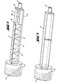
- the static mixer comprises a jacket tube 1 with an inlet opening 2, through which the components of the multi-component compositions are introduced into the static mixer and mixed there, and an outlet opening 3 for the mix.
- the jacket tube 1 at least one mixing section 4 is provided in which one or more mixing elements 5 are provided, which are adapted in their outer dimensions to the inner dimensions of the jacket tube.
- at least one chamber 6 is provided in the jacket tube, in which the additives to be introduced into the mix are arranged.
- the chamber 6 can be arranged in the conveying direction before or after the mixing section 4 or between two mixing sections 4.
- the jacket tube 1 may have a circular, oval and / or angular, preferably circular and / or square inner cross section, wherein the outer cross section may be formed as desired. Furthermore, the defined by the jacket tube 1 interior can be cylindrically shaped, that is, the cross-sectional area is the same in all areas. On the other hand, it is also possible that the cross-sectional area of the jacket tube increases or decreases from the inlet opening to the outlet opening, but preferably decreases, that is, the jacket tube 1 narrows from the inlet opening 2 to the outlet opening third
- the at least one chamber 6 for receiving the introduced into the mix additives 7 at its inlet end or its outlet end by at least one matched in their outer dimensions to the inner dimensions of the casing tube 1 demarcation. This delimitation should be permeable to the mix, but withhold the added to the mix but not yet dissolved or not dispersed in the mix additives 7.
- the at least one chamber 6 is delimited by two delimitations 8 and 9.
- delimitations 8 or 9 may be in the form of a sieve, a perforated plate, a sintered plate and / or a fleece or filter material, for example in the form of a filter bag, these delimitations being arbitrary Materials can be made, for example, paper, metal, glass and / or plastic.
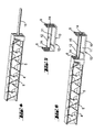
- the embodiment of the static mixer according to the invention shown in Figures 2 to 6 has a square casing tube 1 with square inner and outer cross-section.
- the jacket tube has an inlet opening 2 and an outlet opening 3, wherein at the inlet opening 2 of the jacket tube, a plug connection, screw connection, clamp connection and / or bayonet connection, preferably a thread, is provided for releasably securing the jacket tube to the outlet opening of the components of the liquid , reactive multi-component composition in separate storage containers containing, not shown in the drawing, Auspreß réelles.
- the connector, screw, clamp connection and / or bayonet connection or the thread 17 may be provided with a suitable seal, which prevents the escape of the mix at the junction.
- FIG. 2 shows the mixing element 5 arranged in the mixing section of the jacket tube in a dashed representation and a container 13 present in the chamber 6 for receiving the additives 7 to be introduced into the mix, this container likewise being shown in dashed lines.
- FIG. 3 shows a schematic representation of the jacket tube 1 of this embodiment of the static mixer with the inlet opening 2 and the thread 17 present there as well as the outlet opening 3.
- FIG. 4 shows the mixing element 5 taken out of the jacket tube 1, wherein the shape of the mixing element known per se corresponds to that of a Kenics mixer known per se.
- the mixing element 5 has at one end the centering mandrel 15, for centering the container 13 shown in Figure 5 for receiving the introduced into the mix, not shown additives 7.
- This container 13 is formed from the boundaries 8 and 9, for the Mixtures are permeable, but retains the introduced into the mix but not yet dissolved or dispersed additives 7.
- the boundaries 8 and 9 are at one to the inner dimensions the chamber 6 adapted longitudinal beams 10 attached.
- this side rail 10 has side walls 11 and 12 and in this way forms an upwardly open container 13 for receiving the additives to be introduced into the mix 7.
- the boundaries 8 and 9 have openings 14 which make it possible Move container on the centering pin 15 on the mixing element 5.
- the inner diameter of the openings 14 is adapted to the outer diameter of the centering mandrel 15 that a penetration of the mixed material between the inner edge of the openings 14 and the outer periphery of the centering mandrel 15 is largely prevented.
- the container 13 shown in FIG. 5 is charged with the additives 7 to be introduced into the mix, pushed onto the centering pin 15 and the combination of the mixing part 5 and the container 13 shown in FIG introduced in Figure 3 jacket tube 1.
- the combination formed in this manner is then threaded over the thread 17 at the exit port of a squeezing device containing the components of the multi-component liquid reactive compositions in separate reservoirs and secured in such a manner as to prevent leakage of the mixture at the point of connection.
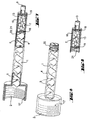
- the static mixer comprises a cylindrical shaped jacket tube 1 with a circular cross-section, which is provided at its inlet opening 2 with a thread 17, for fixing the jacket tube to a squeezing device, as already above has been addressed.
- the mixing section 4 is the mixing element 5, which is shown in dashed lines.
- the chamber 6 is in the form of a releasably connected to the adjacent casing tube 1 and the outlet opening 3 casing pipe piece 16. As shown in FIG. 7, the additives 7 are arranged in this casing pipe section 16.
- the casing pipe section 16 is adapted in its inner cross-section and its cross-sectional surface profile to the circular, oval and / or angular, preferably circular and / or square inner cross-section and the cross-sectional profile of the jacket tube 1.
- the casing pipe piece 16 is also cylindrical and has a circular cross-section which corresponds to that of the casing tube 1.
- the casing pipe piece 16 is fixedly connected to the outlet opening 3 and releasably connected to the casing tube 1, in particular via the threaded connection 20, 21 on the casing tube 1 or the casing pipe piece 16.
- casing pipe section 16 and outlet opening 3 integrally formed, preferably in the form of a molded plastic part, which has been produced for example by injection molding and can be connected via the thread 21 with the jacket tube 1.
- removable separations 18, 19 are provided between the casing pipe section 16 and the casing pipe 1 or before the outlet opening 3, preferably in the form of screens, perforated plates and / or sintered plates made of paper, metal, plastic and / or glass or in the form of a non-woven or Filter material, such as a filter bag.
- the at least one mixing element 5, the container 13 and the boundaries 8, 9, 18, 19 secured against rotation and displacement in the conveying direction for example by the configuration of the inner cross section of the jacket tube, or the outer cross section of the mixing elements 5, the boundaries 8, 9, 18, 19 and the container 13, by grooves in the inner surface of the jacket tube and corresponding lugs of the mixing elements 5, the boundaries 8, 9, 18, 19 and the container 13th
- the boundaries 8, 9, 18, 19 such sized openings that the mix can penetrate, but are retained in the mix to be introduced but not yet dissolved or dispersed additives.
- these openings which are in the form of holes, screen openings, sintering openings, pores or the like, dimensions corresponding to a diameter of 0.2 mm to 2.0 mm, preferably 1 mm to 1.5 mm.
- At least one mixing element 5 is arranged in the at least one chamber 6 or the casing pipe piece 16, which carries on at least one of its surfaces the additives 7 to be introduced into the mix, or is formed from these additives 7.
- this mixing element of a catalytically active material which catalyzes and accelerates the reaction of the reacting mixture formed from the liquid, reactive components of the multi-component compositions. In this way, it is achieved that while the passage material has a sufficiently low viscosity for the passage through the static mixer, but on exit from the outlet opening 3 has a viscosity which prevents the material from flowing down after being applied to ceilings or walls ,
- the mixing elements 5 are shaped to effect mixing of the constituents of the mix by utilizing the flow energy of the components of the liquid reactive multi-component composition introduced under pressure into the static mixer.
- the mixing elements 5 are secured against rotation in the jacket tube 1, for example by grooves in the inner wall of the jacket tube and corresponding lugs on the outside of the mixing elements fifth
- the jacket tube of the static mixer according to the invention can also have a plug-in connection, screw connection, clamping connection and / or bayonet connection preventing the outlet of the mixture at the connection point, but preferably a thread with which the jacket tube can be fastened to the outlet opening of a squeezing device which contains the components of the liquid, reactive multicomponent composition in separate storage containers. This is done after arranging the introduced into the mix additives 7 in the chamber 6. The choice of type and amount of these additives depending on the ongoing reaction between the liquid, reactive components of the multi-component composition and the resulting in the static mixer formed Mischguts and the desired properties of the emerging from the outlet opening 3 of the static mixer mixed material.
- Another object of the invention relates to the use of the static mixer described above for the introduction of additives in the mix, which are suitable for modifying the physical and / or chemical properties of the liquid mixture formed from the liquid, reactive multi-component composition.
- additives which increase the viscosity of the mix.
- the static mixer according to the invention is used to increase the viscosity of a liquid fire-resistant foam produced in the at least one mixing section 4 and not yet fully reacted.
- the static mixer according to the invention for the speed of the polyurethane formation and the foaming process to introduce an additive from the liquid, reactive multi-component composition formed liquid polyurethane foam system additives in the mix and mix it homogeneously.
Claims (33)
- Mélangeur statique pour mélanger des composants de composés fluides réactifs à plusieurs composants, avec un tube enveloppe (1) définissant au moins une portion de mélange, avec une ouverture d'entrée (2) et une ouverture de sortie (3) pour le produit mélangé, et avec au moins un élément mélangeur (5) qui est disposé dans la portion de mélange (4) et dont les dimensions extérieures sont adaptées aux dimensions intérieures du tube enveloppe (1), caractérisé par au moins une chambre (6) qui est située dans le tube enveloppe (1) entre l'ouverture d'entrée (2) et l'ouverture de sortie (3) et qui sert à recevoir des adjuvants (7) à incorporer au produit mélangé.
- Mélangeur statique selon la revendication 1, caractérisé en ce que la chambre (6) est disposée avant ou après la portion de mélange (4) par rapport à la direction d'alimentation ou entre deux portions de mélange (4).
- Mélangeur statique selon la revendication 1 ou 2, caractérisé en ce que le-tube enveloppe (1) possède une section transversale intérieure circulaire, ovale et/ou polygonale, de préférence circulaire et/ou carrée.
- Mélangeur statique selon la revendication 3, caractérisé en ce que l'espace intérieur défini par le tube enveloppe (1) est de forme cylindrique ou sa surface de section transversale diminue de l'ouverture d'entrée (2) vers l'ouverture de sortie (3).
- Mélangeur statique selon au moins une des revendications 1 à 4, caractérisé en ce que la chambre au nombre d'au moins une (6) est limitée à son extrémité d'admission, respectivement à son extrémité d'évacuation par au moins un moyen de délimitation (8, respectivement 9) dont les dimensions extérieures sont adaptées aux dimensions intérieures du tube enveloppe (1) et qui est perméable au produit mélangé, mais qui retient les adjuvants (7) non dissous ou non dispersés à incorporer au produit mélangé.
- Mélangeur statique selon la revendication 5, caractérisé en ce que la chambre au nombre d'au moins une (6) est limitée par deux moyens de délimitation (8, respectivement 9).
- Mélangeur statique selon la revendication 5 ou 6, caractérisé en ce que le moyen de délimitation au nombre d'au moins un (8, respectivement 9) se présente sous la forme d'un tamis, d'une plaque perforée, d'une plaque frittée, d'une matière non tissée et/ou d'une poche filtrante.
- Mélangeur statique selon les revendications 5 à 7, caractérisé en ce que le moyen de délimitation au nombre d'au moins un (8, respectivement 9) de la chambre au nombre d'au moins une (6) est fixé à un longeron (10) adapté aux dimensions intérieures de la chambre (6).
- Mélangeur statique selon la revendication 8, caractérisé en ce que le longeron (10) comporte des parois latérales (11, 12) qui définissent un récipient (13) pour recevoir les adjuvants (7) à incorporer au produit mélangé.
- Mélangeur statique selon au moins une des revendications 5 à 9, caractérisé en ce que le moyen de délimitation au nombre d'au moins un (8, respectivement 9) de la chambre au nombre d'au moins une (6) est pourvu d'ouvertures (14) pour recevoir une broche de centrage (15) fixée à l'extrémité de la portion de mélange (4).
- Mélangeur statique selon la revendication 10, caractérisé en ce que la broche de centrage (15) est fixée à l'élément mélangeur voisin (5).
- Mélangeur statique selon au moins une des revendications précédentes, caractérisé en ce que la chambre (6) est formée par un tronçon de tube enveloppe (16) relié de manière détachable au tube enveloppe voisin (1) et à l'ouverture de sortie (3).
- Mélangeur statique selon la revendication 12, caractérisé en ce que la section transversale intérieure et le profil de la surface de section transversale du tronçon de tube enveloppe (16) sont adaptés à la section transversale intérieure circulaire, ovale et/ou polygonale, de préférence circulaire et/ou carrée, et au profil de la surface de section transversale du tube enveloppe (1).
- Mélangeur statique selon les revendications 12 et 13, caractérisé en ce que le tronçon de tube enveloppe (16) est fixé de manière solidaire à l'ouverture de sortie (3) et de manière détachable au tube enveloppe (1).
- Mélangeur statique selon au moins une des revendications 12 à 14, caractérisé en ce que le tronçon de tube enveloppe (16) et l'ouverture de sortie (3) sont réalisés d'un seul tenant.
- Mélangeur statique selon au moins une des revendications 12 à 15, caractérisé en ce que, entre le tronçon de tube enveloppe (16) et le tube enveloppe (1), respectivement avant l'ouverture de sortie (3), sont prévus des moyens de délimitation amovibles (18, respectivement 19).
- Mélangeur statique selon la revendication 16, caractérisé en ce que les moyens de délimitation amovibles (18, 19) se présentent sous la forme de tamis, de plaques perforées, de plaques frittées, de matières non tissées et/ou de poches filtrantes.
- Mélangeur statique selon la revendication 17, caractérisé en ce que les moyens de délimitation amovibles (18, 19) sont immobilisés en translation dans la direction d'alimentation.
- Mélangeur statique selon au moins une des revendications précédentes, caractérisé en ce que les moyens de délimitation (8, 9, 18, 19) sont pourvus d'ouvertures dimensionnées de façon à laisser passer le produit mélangé, mais à retenir les adjuvants non dissous ou non dispersés à incorporer dans le produit mélangé.
- Mélangeur statique selon la revendication 19, caractérisé en ce que les ouvertures des moyens de délimitation (8, 9, 18, 19) possèdent un diamètre de 0,2 à 2 mm, de préférence de 1 à 1,5 mm.
- Mélangeur statique selon au moins une des revendications précédentes, caractérisé en ce que dans la chambre au nombre d'au moins une (6) ou dans le tronçon de tube enveloppe (16) est disposé au moins un élément mélangeur (5) qui porte, sur ses surfaces, les adjuvants (7) à incorporer dans le produit mélangé, respectivement qui en est constitué.
- Mélangeur statique selon au moins une des revendications précédentes, caractérisé en ce que la surface intérieure de la chambre au nombre d'au moins une (6) et/ou du tronçon de tube enveloppe (16) porte les adjuvants (7) à incorporer dans le produit mélangé, respectivement en est constituée.
- Mélangeur statique selon au moins une des revendications précédentes, caractérisé en ce que les éléments mélangeurs (5) sont conformés de façon à réaliser le mélange des éléments constitutifs du produit mélangé en utilisant l'énergie d'écoulement des composants, introduits sous pression dans le mélangeur statique, des composés fluides réactifs à plusieurs composants.
- Mélangeur statique selon au moins une des revendications précédentes, caractérisé en ce que les éléments mélangeurs (5) sont immobilisés en rotation dans le tube enveloppe (1).
- Mélangeur statique selon au moins une des revendications précédentes, caractérisé en ce que les dimensions extérieures des éléments mélangeurs (5) et des moyens de délimitation (8, 9, 18, 19) sont adaptées aux dimensions intérieures du tube enveloppe (1), respectivement du tronçon de tube enveloppe (16), de façon à empêcher le produit mélangé de passer entre la paroi intérieure du tube enveloppe (1) et la périphérie extérieure des éléments mélangeurs (5) et celle des moyens de délimitation (8, 9, 18, 19).
- Mélangeur statique selon au moins une des revendications précédentes, caractérisé en ce que, pour relier le tronçon de tube enveloppe (16) de manière détachable au tube enveloppe (1) et à l'ouverture de sortie (3), il est prévu une liaison par emboîtement, une liaison par vissage, une liaison par serrage et/ou une liaison à baïonnette qui empêche le produit mélangé de sortir au niveau de la zone de liaison.
- Mélangeur statique selon la revendication 26, caractérisé en ce que la liaison détachable du tronçon de tube enveloppe (16) au tube enveloppe (1) et à l'ouverture de sortie (3) s'effectue par l'intermédiaire d'une liaison vissée (20, 21).
- Mélangeur statique selon au moins une des revendications précédentes, caractérisé en ce que le tube enveloppe (1), le tronçon de tube enveloppe (16), les éléments mélangeurs (5), les éléments constitutifs du récipient (13) et les moyens de délimitation (8, 9, 18, 19) sont réalisés en verre, en matière plastique et/ou en métal.
- Mélangeur statique selon au moins une des revendications précédentes, caractérisé en ce qu'au niveau de l'ouverture d'entrée (2) du tube enveloppe (1) est prévue une liaison par emboîtement, une liaison par vissage, une liaison par serrage et/ou une liaison à baïonnette, de préférence un filetage (17), pour la fixation détachable à l'ouverture de sortie d'un outil d'extrusion contenant les composants du composé fluide réactif à plusieurs composants placés dans des réservoirs séparés.
- Utilisation du mélangeur statique selon au moins une des revendications précédentes pour introduire, dans le produit mélangé fluide formé à partir du composé fluide réactif à plusieurs composants, des adjuvants modifiant les propriétés physiques et/ou chimiques dudit produit mélangé.
- Utilisation selon la revendication 30 pour incorporer des adjuvants augmentant la viscosité du produit mélangé fluide formé à partir du composé fluide réactif à plusieurs composants.
- Utilisation selon la revendication 31 pour augmenter la viscosité d'une mousse antifeu fluide qui n'est pas encore entrée en réaction et qui est produite dans au moins une portion de mélange (4).
- Utilisation selon la revendication 30 pour incorporer, dans le système de mousse polyuréthanne liquide formé à partir du composé fluide réactif à plusieurs composants, des adjuvants augmentant la vitesse de formation du polyuréthanne et celle du processus de moussage du système de mousse polyuréthanne.
Applications Claiming Priority (2)
| Application Number | Priority Date | Filing Date | Title |
|---|---|---|---|
| DE102004008755A DE102004008755A1 (de) | 2004-02-23 | 2004-02-23 | Statischer Mischer und seine Verwendung |
| DE102004008755 | 2004-02-23 |
Publications (2)
| Publication Number | Publication Date |
|---|---|
| EP1566211A1 EP1566211A1 (fr) | 2005-08-24 |
| EP1566211B1 true EP1566211B1 (fr) | 2006-09-27 |
Family
ID=34706896
Family Applications (1)
| Application Number | Title | Priority Date | Filing Date |
|---|---|---|---|
| EP05101279A Not-in-force EP1566211B1 (fr) | 2004-02-23 | 2005-02-21 | Mélangeur statique et utilisation |
Country Status (7)
| Country | Link |
|---|---|
| US (1) | US7484881B2 (fr) |
| EP (1) | EP1566211B1 (fr) |
| JP (1) | JP2005238232A (fr) |
| CN (1) | CN1669626A (fr) |
| AT (1) | ATE340636T1 (fr) |
| DE (2) | DE102004008755A1 (fr) |
| ES (1) | ES2273308T3 (fr) |
Cited By (1)
| Publication number | Priority date | Publication date | Assignee | Title |
|---|---|---|---|---|
| EP2485852A1 (fr) | 2009-10-06 | 2012-08-15 | Medmix Systems AG | Système de décharge avec un système de liaison entre une cartouche multicomposant et un accessoire |
Families Citing this family (46)
| Publication number | Priority date | Publication date | Assignee | Title |
|---|---|---|---|---|
| KR100707599B1 (ko) * | 2005-06-24 | 2007-04-13 | 삼성에스디아이 주식회사 | 연료혼합탱크 및 이를 구비한 연료전지장치 |
| FR2894942A1 (fr) * | 2005-12-15 | 2007-06-22 | Ronith Stemmer | Dispositif de conditionnement et de distribution de produits dentaires |
| WO2007125642A1 (fr) | 2006-04-05 | 2007-11-08 | Nikkiso Co., Ltd. | melangeur, dispositif de melange et unite de mesure de composant medical |
| US8136980B2 (en) * | 2006-07-27 | 2012-03-20 | Komax Systems, Inc. | Meter flow conditioner |
| JP2008114151A (ja) * | 2006-11-02 | 2008-05-22 | Anemosu:Kk | 流体混合器及び混合要素部材 |
| JP5013073B2 (ja) * | 2007-03-09 | 2012-08-29 | 株式会社エクサ | 2液混合注入装置及びそのミキサ |
| DE102007057763A1 (de) * | 2007-11-30 | 2009-06-04 | Hilti Aktiengesellschaft | Selbstbohrender Verbundanker |
| KR101135614B1 (ko) * | 2008-12-23 | 2012-04-17 | 제일모직주식회사 | 스태틱 믹서용 혼합부재 및 이를 이용하는 스태틱 믹서 |
| DE102009018539A1 (de) * | 2009-04-24 | 2010-11-18 | Bayer Technology Services Gmbh | Modulare Mischer |
| EP2286925B1 (fr) * | 2009-08-20 | 2018-03-14 | Sulzer Mixpac AG | Pulvérisateur avec mélangeur statique |
| EP2368625A1 (fr) * | 2010-03-22 | 2011-09-28 | Sulzer Chemtech AG | Procédé et dispositif destinés à la dispersion |
| AU2011276443A1 (en) * | 2010-06-29 | 2013-01-31 | Covidien Lp | Microwave-powered reactor and method for in situ forming implants |
| MX2013000683A (es) * | 2010-07-20 | 2013-02-27 | Sulzer Mixpac Ag | Mezclador pulverizador estatico. |
| US20120294680A1 (en) * | 2011-05-18 | 2012-11-22 | Mcclellan Richard Stanton | Device and method for anchoring a cable bolt |
| RU2584990C2 (ru) * | 2011-05-19 | 2016-05-27 | Минова Интернешнл Лтд | Способ закрепления тросового анкера |
| DE202011101066U1 (de) * | 2011-05-25 | 2011-09-15 | Ritter Gmbh | Statischer Mischer |
| CN102500259B (zh) * | 2011-10-28 | 2014-03-26 | 彭墘精 | 射嘴静态色浆混合器 |
| US20130112783A1 (en) * | 2011-11-08 | 2013-05-09 | Christopher I. JOHNSON | Hose adapter |
| US20130128688A1 (en) * | 2011-11-18 | 2013-05-23 | Michael B. Doolin | Flow Reversing Static Mixer and Method |
| DE102012209517B3 (de) * | 2012-06-06 | 2013-11-07 | Henkel Ag & Co. Kgaa | Aufschäumvorrichtung |
| US20140091489A1 (en) * | 2012-10-03 | 2014-04-03 | Trexel, Inc. | Blowing agent introduction in polymer foam processing |
| US9492798B2 (en) * | 2013-04-19 | 2016-11-15 | Vaughan Industries Inc. | Foam generation assembly and method for manufacturing the foam generation assembly |
| CA2969313C (fr) * | 2014-06-03 | 2020-06-16 | Scale Protection As | Dispositif et procede pour la reduction du tartre dans une zone d'eau stagnante d'un conduit de fluide |
| US20160001255A1 (en) | 2014-07-03 | 2016-01-07 | Chevron U.S.A. Inc. | Novel reactor for ionic liquid catalyzed alkylation based on motionless mixer |
| CN104280488A (zh) * | 2014-10-24 | 2015-01-14 | 王峰 | 一种液相色谱分析仪用静态混合器 |
| EP3034159B1 (fr) * | 2014-12-18 | 2020-11-04 | The Procter and Gamble Company | Mélangeur statique et procédé pour mélanger des fluides |
| CN104535699B (zh) * | 2015-01-05 | 2018-04-03 | 上海谱宁分析技术有限公司 | 峰形前延抑制器、使用其的高效液相色谱分析装置及方法 |
| US20160273847A1 (en) * | 2015-03-20 | 2016-09-22 | Hamilton Sundstrand Corporation | Heat exchanger distributor swirl vane |
| US10729600B2 (en) | 2015-06-30 | 2020-08-04 | The Procter & Gamble Company | Absorbent structure |
| US10850236B2 (en) | 2015-08-31 | 2020-12-01 | Palo Alto Research Center Incorporated | Low dispersion, fast response mixing device |
| MX2018005609A (es) | 2015-11-04 | 2018-11-09 | Procter & Gamble | Estructura absorbente. |
| US11173078B2 (en) | 2015-11-04 | 2021-11-16 | The Procter & Gamble Company | Absorbent structure |
| EP3662992B1 (fr) * | 2017-08-22 | 2022-08-10 | LG Chem, Ltd. | Procédé de mélange de composants de matériau de dissipation thermique |
| RS62976B1 (sr) * | 2017-09-01 | 2022-03-31 | Metso Outotec Finland Oy | Uređaj za distribuciju smeše za napajanje gorionika |
| DE102017128116B4 (de) | 2017-11-28 | 2019-06-13 | Coexal Gmbh | Mischerkomponente, Statischer Mischer und Verfahren zu deren Herstellung |
| JP6512344B1 (ja) * | 2018-05-23 | 2019-05-15 | 東洋インキScホールディングス株式会社 | 積層体の製造方法及び接着剤の塗工方法 |
| HUE056956T2 (hu) * | 2018-05-29 | 2022-04-28 | Soudal | Adagolórendszer két komponensbõl lévõ keverékhez és statikus keverõfúvóka ahhoz |
| CN109531851B (zh) * | 2019-01-16 | 2023-08-01 | 浙江富士特硅橡胶材料有限公司 | 一种婴童用品用加成型液体硅橡胶混料装置 |
| USD1009221S1 (en) * | 2020-12-18 | 2023-12-26 | Commonwealth Scientific And Industrial Research Organisation | Static mixer |
| USD1008485S1 (en) * | 2020-12-18 | 2023-12-19 | Commonwealth Scientific And Industrial Research Organisation | Static mixer |
| USD1008417S1 (en) * | 2020-12-18 | 2023-12-19 | Commonwealth Scientific And Industrial Research Organisation | Static mixer |
| USD1008418S1 (en) * | 2020-12-18 | 2023-12-19 | Commonwealth Scientific And Industrial Research Organisation | Static mixer |
| USD1009216S1 (en) * | 2020-12-18 | 2023-12-26 | Commonwealth Scientific And Industrial Research Organisation | Static mixer |
| USD1009222S1 (en) * | 2020-12-18 | 2023-12-26 | Commonwealth Scientific And Industrial Research Organisation | Static mixer |
| USD992691S1 (en) * | 2020-12-18 | 2023-07-18 | Commonwealth Scientific And Industrial Research Organisation | Static mixer |
| DE202021002842U1 (de) | 2021-09-02 | 2022-01-19 | IAB-Institut für Angewandte Bauforschung Weimar gemeinnützige GmbH | Vorrichtung zur schonenden Homogenisierung zweier getrennt erzeugter Schäume zu einem Schaum |
Family Cites Families (21)
| Publication number | Priority date | Publication date | Assignee | Title |
|---|---|---|---|---|
| US302675A (en) * | 1884-07-29 | Wallace suits | ||
| US1626487A (en) * | 1924-01-10 | 1927-04-26 | Warren David | Emulsifier |
| US1857348A (en) * | 1928-05-14 | 1932-05-10 | Bokenkroger William | Filter for gaseous substances |
| US2006085A (en) * | 1933-04-01 | 1935-06-25 | Henry W Lehmkuhl | Washing apparatus |
| US2600733A (en) * | 1950-12-06 | 1952-06-17 | Standard Oil Co | Gas mixing apparatus |
| US3018841A (en) * | 1960-01-04 | 1962-01-30 | Gerlich Stephen | Muffler |
| BE754657Q (fr) * | 1965-11-29 | 1971-01-18 | Kenics Corp | Appareil melangeur |
| US4293425A (en) * | 1976-10-27 | 1981-10-06 | Kenneth E. Price | Method of chlorinating swimming pools and the like |
| US4204775A (en) * | 1978-08-08 | 1980-05-27 | General Dynamics Corporation Pomona Division | Mixing device for simultaneously dispensing two-part liquid compounds from packaging kit |
| DE3609556C1 (en) * | 1986-03-21 | 1987-10-22 | Joachim Sinsch | Static mixer |
| DE3644459A1 (de) * | 1986-12-24 | 1988-07-07 | Basf Ag | Kontinuierliches verfahren zur herstellung von loesungen aus niederviskosen loesungsmitteln und hochviskosen, pastoesen produkten |
| USRE36235E (en) * | 1987-01-16 | 1999-06-29 | Wilhelm Keller | Dispensing and mixing apparatus |
| JPS63258626A (ja) * | 1987-04-16 | 1988-10-26 | Aoki Kensetsu:Kk | 粘性物の撹拌混合方法とその装置 |
| AU3310293A (en) * | 1992-03-04 | 1993-09-09 | Rohm And Haas Company | Process and device for metering of solutes into liquids |
| JPH06296974A (ja) * | 1993-04-19 | 1994-10-25 | Nippon Soda Co Ltd | 導入水型固型薬剤溶解器及びそれを用いた水の塩素処理方法 |
| DE4412261C2 (de) * | 1994-04-09 | 1996-10-17 | Jonas Konrad H | Vorrichtung zum Zusammenführen wenigstens zweier Fließmedien |
| DE19730424A1 (de) | 1997-07-16 | 1999-01-21 | Henkel Teroson Gmbh | Vorrichtung zum Lagern und Auspressen von fließfähigen Zusammensetzungen |
| US5904851A (en) * | 1998-01-19 | 1999-05-18 | Life International Products, Inc. | Oxygenating apparatus, method for oxygenating liquid therewith, and applications thereof |
| US6062492A (en) * | 1998-05-15 | 2000-05-16 | Sealant Equipment & Engineering, Inc. | Viscous material dispense system |
| DE10297145T5 (de) * | 2001-08-24 | 2004-07-22 | Dober Chemical Corporation, Midlothian | Kontrollierte Freisetzung von Additiven in Fluidsysteme |
| US6677387B2 (en) * | 2002-06-03 | 2004-01-13 | Intevep, S.A. | Preparation of stable emulsion using dynamic or static mixers |
-
2004
- 2004-02-23 DE DE102004008755A patent/DE102004008755A1/de not_active Withdrawn
-
2005
- 2005-02-18 CN CNA2005100093863A patent/CN1669626A/zh active Pending
- 2005-02-21 DE DE502005000116T patent/DE502005000116D1/de active Active
- 2005-02-21 EP EP05101279A patent/EP1566211B1/fr not_active Not-in-force
- 2005-02-21 AT AT05101279T patent/ATE340636T1/de active
- 2005-02-21 ES ES05101279T patent/ES2273308T3/es active Active
- 2005-02-23 US US11/063,958 patent/US7484881B2/en not_active Expired - Fee Related
- 2005-02-23 JP JP2005047183A patent/JP2005238232A/ja active Pending
Cited By (2)
| Publication number | Priority date | Publication date | Assignee | Title |
|---|---|---|---|---|
| EP2485852A1 (fr) | 2009-10-06 | 2012-08-15 | Medmix Systems AG | Système de décharge avec un système de liaison entre une cartouche multicomposant et un accessoire |
| US9010578B2 (en) | 2009-10-06 | 2015-04-21 | Medix Systems AG | Discharge arrangement having a connecting device between a multi-component cartridge and an accessory part |
Also Published As
| Publication number | Publication date |
|---|---|
| CN1669626A (zh) | 2005-09-21 |
| DE502005000116D1 (de) | 2006-11-09 |
| ATE340636T1 (de) | 2006-10-15 |
| ES2273308T3 (es) | 2007-05-01 |
| JP2005238232A (ja) | 2005-09-08 |
| EP1566211A1 (fr) | 2005-08-24 |
| US20050185508A1 (en) | 2005-08-25 |
| DE102004008755A1 (de) | 2005-09-08 |
| US7484881B2 (en) | 2009-02-03 |
Similar Documents
| Publication | Publication Date | Title |
|---|---|---|
| EP1566211B1 (fr) | Mélangeur statique et utilisation | |
| EP0755300B1 (fr) | Procede et dispositif pour la confluence d'au moins deux substances fluides | |
| DE69930615T2 (de) | Zusammenstellung und verfahren zur dispersion und bereitstellung von fluiden | |
| EP1268046B1 (fr) | Buse de moussage, de pulverisation ou d'atomisation | |
| DE2708200C2 (de) | Statische Mischeinrichtung für eine Kunststoffmaschine, insbesondere Spritzgießmaschine oder Extruder | |
| EP1588757B1 (fr) | Mélangeur statique pour la production de mélanges durcissables de composants liquides, et son utilisation | |
| EP2548634B1 (fr) | Elément de mélange pour mélangeur statique | |
| DE10019893C2 (de) | Vorrichtung in Form eines dynamischen Mischers oder einer Kartuschenfront und deren Verwendung | |
| EP1825925B1 (fr) | Dispositif et procédé pour mélanger un composant liant et un composant durcisseur afin de produire une matière à enduire prête à l'emploi. | |
| EP1402940A2 (fr) | Mélangeur pour pâtes à plusieurs constituants | |
| EP1885620A1 (fr) | Applicateur pour deux composants ou plus | |
| DE1557118B2 (fr) | ||
| EP0090257B1 (fr) | Dispositif pour la production d'un mélange chimiquement réactif d'au moins deux composants plastiques liquides | |
| DE202007016136U1 (de) | Gerät zur Herstellung einer gebrauchsfertigen Spachtelmasse durch Vermischen einer Binder- und einer Härter-Komponente | |
| DE10347938A1 (de) | Kopfteil für einen Mehrkammerschlauchbeutel | |
| EP1593473B1 (fr) | Tête de mélange multicomposantes | |
| EP1900443B1 (fr) | Système d'appareils destiné à la fabrication de mastic prêt à l'emploi par le mélange de composants liants et durcisseurs | |
| EP1825924B1 (fr) | Appareil et méthode pour mélanger un liant et un durcisseur pour produire un mastic prêt à l'emploi | |
| EP2975487B1 (fr) | Dispositif destiné à doser et mélanger deux composants pouvant s'écouler | |
| EP2651546B1 (fr) | Appareil permettant d'élaborer une masse à jointoyer prête à l'emploi par mélange d'un composant liant et d'un composant durcisseur, et son utilisation | |
| EP1974804A2 (fr) | Dispositif destiné au mélange d'un composant liant et d'un composant durcissant destiné à la fabrication d'un mastique prêt à l'emploi | |
| DE1683960C3 (de) | Vorrichtung zum Herstellen und Aufbringen eines ein wärmehärtbares Kunstharz und einen mineralischen Füllstoff enthaltenden Mörtels sowie Verfahren zum Aufbringen des Mörtels auf eine Fläche | |
| EP1731216A1 (fr) | Insert de mixage et méthode de pré-mixage de deux composants fluides | |
| DE10016926C2 (de) | Vorrichtung zum Aufschäumen | |
| EP0896833A1 (fr) | Dispositif d'homogénéisation des matiériaux aptes a couler |
Legal Events
| Date | Code | Title | Description |
|---|---|---|---|
| PUAI | Public reference made under article 153(3) epc to a published international application that has entered the european phase |
Free format text: ORIGINAL CODE: 0009012 |
|
| AK | Designated contracting states |
Kind code of ref document: A1 Designated state(s): AT BE BG CH CY CZ DE DK EE ES FI FR GB GR HU IE IS IT LI LT LU MC NL PL PT RO SE SI SK TR |
|
| AX | Request for extension of the european patent |
Extension state: AL BA HR LV MK YU |
|
| GRAP | Despatch of communication of intention to grant a patent |
Free format text: ORIGINAL CODE: EPIDOSNIGR1 |
|
| 17P | Request for examination filed |
Effective date: 20060224 |
|
| AKX | Designation fees paid |
Designated state(s): AT BE BG CH CY CZ DE DK EE ES FI FR GB GR HU IE IS IT LI LT LU MC NL PL PT RO SE SI SK TR |
|
| GRAS | Grant fee paid |
Free format text: ORIGINAL CODE: EPIDOSNIGR3 |
|
| GRAA | (expected) grant |
Free format text: ORIGINAL CODE: 0009210 |
|
| AK | Designated contracting states |
Kind code of ref document: B1 Designated state(s): AT BE BG CH CY CZ DE DK EE ES FI FR GB GR HU IE IS IT LI LT LU MC NL PL PT RO SE SI SK TR |
|
| PG25 | Lapsed in a contracting state [announced via postgrant information from national office to epo] |
Ref country code: RO Free format text: LAPSE BECAUSE OF FAILURE TO SUBMIT A TRANSLATION OF THE DESCRIPTION OR TO PAY THE FEE WITHIN THE PRESCRIBED TIME-LIMIT Effective date: 20060927 Ref country code: LT Free format text: LAPSE BECAUSE OF FAILURE TO SUBMIT A TRANSLATION OF THE DESCRIPTION OR TO PAY THE FEE WITHIN THE PRESCRIBED TIME-LIMIT Effective date: 20060927 Ref country code: IT Free format text: LAPSE BECAUSE OF FAILURE TO SUBMIT A TRANSLATION OF THE DESCRIPTION OR TO PAY THE FEE WITHIN THE PRESCRIBED TIME-LIMIT;WARNING: LAPSES OF ITALIAN PATENTS WITH EFFECTIVE DATE BEFORE 2007 MAY HAVE OCCURRED AT ANY TIME BEFORE 2007. THE CORRECT EFFECTIVE DATE MAY BE DIFFERENT FROM THE ONE RECORDED. Effective date: 20060927 Ref country code: SK Free format text: LAPSE BECAUSE OF FAILURE TO SUBMIT A TRANSLATION OF THE DESCRIPTION OR TO PAY THE FEE WITHIN THE PRESCRIBED TIME-LIMIT Effective date: 20060927 Ref country code: FI Free format text: LAPSE BECAUSE OF FAILURE TO SUBMIT A TRANSLATION OF THE DESCRIPTION OR TO PAY THE FEE WITHIN THE PRESCRIBED TIME-LIMIT Effective date: 20060927 Ref country code: PL Free format text: LAPSE BECAUSE OF FAILURE TO SUBMIT A TRANSLATION OF THE DESCRIPTION OR TO PAY THE FEE WITHIN THE PRESCRIBED TIME-LIMIT Effective date: 20060927 Ref country code: SI Free format text: LAPSE BECAUSE OF FAILURE TO SUBMIT A TRANSLATION OF THE DESCRIPTION OR TO PAY THE FEE WITHIN THE PRESCRIBED TIME-LIMIT Effective date: 20060927 Ref country code: CZ Free format text: LAPSE BECAUSE OF FAILURE TO SUBMIT A TRANSLATION OF THE DESCRIPTION OR TO PAY THE FEE WITHIN THE PRESCRIBED TIME-LIMIT Effective date: 20060927 Ref country code: IE Free format text: LAPSE BECAUSE OF FAILURE TO SUBMIT A TRANSLATION OF THE DESCRIPTION OR TO PAY THE FEE WITHIN THE PRESCRIBED TIME-LIMIT Effective date: 20060927 |
|
| REG | Reference to a national code |
Ref country code: GB Ref legal event code: FG4D Free format text: NOT ENGLISH |
|
| REG | Reference to a national code |
Ref country code: CH Ref legal event code: EP |
|
| REG | Reference to a national code |
Ref country code: IE Ref legal event code: FG4D Free format text: LANGUAGE OF EP DOCUMENT: GERMAN |
|
| REF | Corresponds to: |
Ref document number: 502005000116 Country of ref document: DE Date of ref document: 20061109 Kind code of ref document: P |
|
| GBT | Gb: translation of ep patent filed (gb section 77(6)(a)/1977) |
Effective date: 20061106 |
|
| PG25 | Lapsed in a contracting state [announced via postgrant information from national office to epo] |
Ref country code: SE Free format text: LAPSE BECAUSE OF FAILURE TO SUBMIT A TRANSLATION OF THE DESCRIPTION OR TO PAY THE FEE WITHIN THE PRESCRIBED TIME-LIMIT Effective date: 20061227 Ref country code: DK Free format text: LAPSE BECAUSE OF FAILURE TO SUBMIT A TRANSLATION OF THE DESCRIPTION OR TO PAY THE FEE WITHIN THE PRESCRIBED TIME-LIMIT Effective date: 20061227 Ref country code: BG Free format text: LAPSE BECAUSE OF FAILURE TO SUBMIT A TRANSLATION OF THE DESCRIPTION OR TO PAY THE FEE WITHIN THE PRESCRIBED TIME-LIMIT Effective date: 20061227 |
|
| PG25 | Lapsed in a contracting state [announced via postgrant information from national office to epo] |
Ref country code: IS Free format text: LAPSE BECAUSE OF FAILURE TO SUBMIT A TRANSLATION OF THE DESCRIPTION OR TO PAY THE FEE WITHIN THE PRESCRIBED TIME-LIMIT Effective date: 20070127 |
|
| PG25 | Lapsed in a contracting state [announced via postgrant information from national office to epo] |
Ref country code: MC Free format text: LAPSE BECAUSE OF NON-PAYMENT OF DUE FEES Effective date: 20070228 |
|
| PG25 | Lapsed in a contracting state [announced via postgrant information from national office to epo] |
Ref country code: PT Free format text: LAPSE BECAUSE OF FAILURE TO SUBMIT A TRANSLATION OF THE DESCRIPTION OR TO PAY THE FEE WITHIN THE PRESCRIBED TIME-LIMIT Effective date: 20070313 |
|
| ET | Fr: translation filed | ||
| REG | Reference to a national code |
Ref country code: IE Ref legal event code: FD4D |
|
| REG | Reference to a national code |
Ref country code: ES Ref legal event code: FG2A Ref document number: 2273308 Country of ref document: ES Kind code of ref document: T3 |
|
| PLBE | No opposition filed within time limit |
Free format text: ORIGINAL CODE: 0009261 |
|
| STAA | Information on the status of an ep patent application or granted ep patent |
Free format text: STATUS: NO OPPOSITION FILED WITHIN TIME LIMIT |
|
| 26N | No opposition filed |
Effective date: 20070628 |
|
| PG25 | Lapsed in a contracting state [announced via postgrant information from national office to epo] |
Ref country code: GR Free format text: LAPSE BECAUSE OF FAILURE TO SUBMIT A TRANSLATION OF THE DESCRIPTION OR TO PAY THE FEE WITHIN THE PRESCRIBED TIME-LIMIT Effective date: 20061228 |
|
| PG25 | Lapsed in a contracting state [announced via postgrant information from national office to epo] |
Ref country code: EE Free format text: LAPSE BECAUSE OF FAILURE TO SUBMIT A TRANSLATION OF THE DESCRIPTION OR TO PAY THE FEE WITHIN THE PRESCRIBED TIME-LIMIT Effective date: 20060927 |
|
| PGRI | Patent reinstated in contracting state [announced from national office to epo] |
Ref country code: IT Effective date: 20090401 |
|
| PG25 | Lapsed in a contracting state [announced via postgrant information from national office to epo] |
Ref country code: CY Free format text: LAPSE BECAUSE OF FAILURE TO SUBMIT A TRANSLATION OF THE DESCRIPTION OR TO PAY THE FEE WITHIN THE PRESCRIBED TIME-LIMIT Effective date: 20060927 Ref country code: LU Free format text: LAPSE BECAUSE OF NON-PAYMENT OF DUE FEES Effective date: 20070221 |
|
| PG25 | Lapsed in a contracting state [announced via postgrant information from national office to epo] |
Ref country code: TR Free format text: LAPSE BECAUSE OF FAILURE TO SUBMIT A TRANSLATION OF THE DESCRIPTION OR TO PAY THE FEE WITHIN THE PRESCRIBED TIME-LIMIT Effective date: 20060927 Ref country code: HU Free format text: LAPSE BECAUSE OF FAILURE TO SUBMIT A TRANSLATION OF THE DESCRIPTION OR TO PAY THE FEE WITHIN THE PRESCRIBED TIME-LIMIT Effective date: 20070328 |
|
| PGFP | Annual fee paid to national office [announced via postgrant information from national office to epo] |
Ref country code: CH Payment date: 20120214 Year of fee payment: 8 Ref country code: FR Payment date: 20120221 Year of fee payment: 8 |
|
| PGFP | Annual fee paid to national office [announced via postgrant information from national office to epo] |
Ref country code: DE Payment date: 20120125 Year of fee payment: 8 |
|
| PGFP | Annual fee paid to national office [announced via postgrant information from national office to epo] |
Ref country code: GB Payment date: 20120215 Year of fee payment: 8 Ref country code: IT Payment date: 20120216 Year of fee payment: 8 Ref country code: BE Payment date: 20120214 Year of fee payment: 8 |
|
| PGFP | Annual fee paid to national office [announced via postgrant information from national office to epo] |
Ref country code: NL Payment date: 20120217 Year of fee payment: 8 |
|
| PGFP | Annual fee paid to national office [announced via postgrant information from national office to epo] |
Ref country code: AT Payment date: 20120126 Year of fee payment: 8 |
|
| PGFP | Annual fee paid to national office [announced via postgrant information from national office to epo] |
Ref country code: ES Payment date: 20120307 Year of fee payment: 8 |
|
| BERE | Be: lapsed |
Owner name: HILTI AKTIENGESELLSCHAFT Effective date: 20130228 |
|
| REG | Reference to a national code |
Ref country code: NL Ref legal event code: V1 Effective date: 20130901 |
|
| REG | Reference to a national code |
Ref country code: CH Ref legal event code: PL |
|
| REG | Reference to a national code |
Ref country code: AT Ref legal event code: MM01 Ref document number: 340636 Country of ref document: AT Kind code of ref document: T Effective date: 20130228 |
|
| GBPC | Gb: european patent ceased through non-payment of renewal fee |
Effective date: 20130221 |
|
| PG25 | Lapsed in a contracting state [announced via postgrant information from national office to epo] |
Ref country code: CH Free format text: LAPSE BECAUSE OF NON-PAYMENT OF DUE FEES Effective date: 20130228 Ref country code: LI Free format text: LAPSE BECAUSE OF NON-PAYMENT OF DUE FEES Effective date: 20130228 Ref country code: AT Free format text: LAPSE BECAUSE OF NON-PAYMENT OF DUE FEES Effective date: 20130228 Ref country code: NL Free format text: LAPSE BECAUSE OF NON-PAYMENT OF DUE FEES Effective date: 20130901 |
|
| REG | Reference to a national code |
Ref country code: FR Ref legal event code: ST Effective date: 20131031 |
|
| REG | Reference to a national code |
Ref country code: DE Ref legal event code: R119 Ref document number: 502005000116 Country of ref document: DE Effective date: 20130903 |
|
| PG25 | Lapsed in a contracting state [announced via postgrant information from national office to epo] |
Ref country code: IT Free format text: LAPSE BECAUSE OF FAILURE TO SUBMIT A TRANSLATION OF THE DESCRIPTION OR TO PAY THE FEE WITHIN THE PRESCRIBED TIME-LIMIT Effective date: 20130221 |
|
| PG25 | Lapsed in a contracting state [announced via postgrant information from national office to epo] |
Ref country code: BE Free format text: LAPSE BECAUSE OF NON-PAYMENT OF DUE FEES Effective date: 20130228 Ref country code: DE Free format text: LAPSE BECAUSE OF NON-PAYMENT OF DUE FEES Effective date: 20130903 Ref country code: FR Free format text: LAPSE BECAUSE OF NON-PAYMENT OF DUE FEES Effective date: 20130228 Ref country code: GB Free format text: LAPSE BECAUSE OF NON-PAYMENT OF DUE FEES Effective date: 20130221 |
|
| REG | Reference to a national code |
Ref country code: ES Ref legal event code: FD2A Effective date: 20140408 |
|
| PG25 | Lapsed in a contracting state [announced via postgrant information from national office to epo] |
Ref country code: ES Free format text: LAPSE BECAUSE OF NON-PAYMENT OF DUE FEES Effective date: 20130222 |