EP1566151B1 - Forceps dentaire composé de deux moitiés séparables - Google Patents
Forceps dentaire composé de deux moitiés séparables Download PDFInfo
- Publication number
- EP1566151B1 EP1566151B1 EP05001310A EP05001310A EP1566151B1 EP 1566151 B1 EP1566151 B1 EP 1566151B1 EP 05001310 A EP05001310 A EP 05001310A EP 05001310 A EP05001310 A EP 05001310A EP 1566151 B1 EP1566151 B1 EP 1566151B1
- Authority
- EP
- European Patent Office
- Prior art keywords
- forceps
- bore
- pliers
- pin
- joint
- Prior art date
- Legal status (The legal status is an assumption and is not a legal conclusion. Google has not performed a legal analysis and makes no representation as to the accuracy of the status listed.)
- Expired - Lifetime
Links
- 230000002093 peripheral effect Effects 0.000 claims abstract description 23
- 239000000463 material Substances 0.000 claims description 9
- 238000003801 milling Methods 0.000 claims description 3
- 238000007514 turning Methods 0.000 claims description 2
- 238000004512 die casting Methods 0.000 claims 1
- 238000004519 manufacturing process Methods 0.000 description 7
- 239000002131 composite material Substances 0.000 description 3
- 238000000605 extraction Methods 0.000 description 3
- 238000004140 cleaning Methods 0.000 description 2
- 238000005553 drilling Methods 0.000 description 2
- 230000000694 effects Effects 0.000 description 2
- 239000002184 metal Substances 0.000 description 2
- 238000004659 sterilization and disinfection Methods 0.000 description 2
- 229910000831 Steel Inorganic materials 0.000 description 1
- 230000015572 biosynthetic process Effects 0.000 description 1
- 230000001419 dependent effect Effects 0.000 description 1
- 230000002349 favourable effect Effects 0.000 description 1
- 238000003754 machining Methods 0.000 description 1
- 230000013011 mating Effects 0.000 description 1
- 238000009497 press forging Methods 0.000 description 1
- 238000000926 separation method Methods 0.000 description 1
- 239000010959 steel Substances 0.000 description 1
- 230000001954 sterilising effect Effects 0.000 description 1
Images


Classifications
-
- A—HUMAN NECESSITIES
- A61—MEDICAL OR VETERINARY SCIENCE; HYGIENE
- A61B—DIAGNOSIS; SURGERY; IDENTIFICATION
- A61B17/00—Surgical instruments, devices or methods
- A61B17/28—Surgical forceps
- A61B17/2812—Surgical forceps with a single pivotal connection
- A61B17/2816—Pivots
-
- A—HUMAN NECESSITIES
- A61—MEDICAL OR VETERINARY SCIENCE; HYGIENE
- A61C—DENTISTRY; APPARATUS OR METHODS FOR ORAL OR DENTAL HYGIENE
- A61C3/00—Dental tools or instruments
- A61C3/14—Dentists' forceps or the like for extracting teeth
-
- A—HUMAN NECESSITIES
- A61—MEDICAL OR VETERINARY SCIENCE; HYGIENE
- A61B—DIAGNOSIS; SURGERY; IDENTIFICATION
- A61B90/00—Instruments, implements or accessories specially adapted for surgery or diagnosis and not covered by any of the groups A61B1/00 - A61B50/00, e.g. for luxation treatment or for protecting wound edges
- A61B90/08—Accessories or related features not otherwise provided for
- A61B2090/0813—Accessories designed for easy sterilising, i.e. re-usable
Definitions
- the invention relates to a dental forceps, in particular an extraction forceps.
- Extraction forceps consist of two forceps parts, each having a jaw and a grip leg.
- the pliers are called by a joint, also called castle or trade, pivotally connected to each other.
- the jaws of the pliers parts form the pliers mouth, while the grip legs form the pliers handle.
- the joint is as an applied joint, in which the two pliers parts are placed and connected to each other, as an inserted joint in which one pliers part is inserted into a cutout of the other pliers part and connected to this, or designed as a plug-through joint, in which one pliers part is pushed through a recess of the other pliers part.
- the two pliers parts are riveted together in the pivot axis, so that the two pliers parts are inextricably linked. It is also known to connect the two pliers parts by a arranged in the pivot axis screw together. Here, a separation of the pliers parts is possible, which is particularly advantageous for cleaning, disinfection and optionally sterilization. However, disassembling the forceps is cumbersome and time consuming.
- the document DE 743 853 C discloses a surgical instrument having a releasable hinge formed from a peripheral lobed pin and a corresponding bore.
- the invention has for its object to provide a dental forceps, which can be easily disassembled and reassembled.
- the joint is formed by a pin formed on one pliers part and a corresponding hole formed in the other pliers part.
- the pin is inserted into the bore and forms the pivot joint, wherein the circular cylindrical pin is guided in the formed with the same diameter circular cylindrical bore.
- the bore has in its wall a circumferential groove and accordingly, the pin has on its outer peripheral surface at least one circumferential tab.
- the peripheral tab of the pin engages in the circumferential groove of the bore, whereby the pin is axially positively held in the bore and whereby the two pliers parts are pivotally connected together.
- the at least one circumferential tab is formed only over a partial angle range of the circumference.
- the pin can be inserted into or pulled out of the bore.
- This angular position corresponds to the spread position of the pliers with maximum opening of the pliers mouth. If the pin is inserted into the hole, the pliers will be in their closing or gripping position pivoted. In this case, the circumferential tab is pivoted in its angular position against the circumferential groove, so that the circumferential tab engages in the circumferential groove and the pin is thereby held axially positive fit in the bore.
- the forceps parts are pivoted in accordance with the required opening of the forceps jaw only in a Sp Dahl Anlagenwitz Anlagenwitz
- the two pliers are therefore always reliably connected to each other for the use of the pliers. If the pliers are to be disassembled for cleaning, the pliers parts have to be spread apart only beyond the normal use pivot position until the at least one circumferential tab comes into the angular range of the at least one inlet channel, so that the pin can now be pulled out of the hole axially and the two pliers parts can be separated from each other.
- the bore is formed as closed at its base blind hole.
- a Bremseinlage between the mutually contacting surfaces of the pin and the bore may be provided.
- This brake insert has the function of causing a defined resistance in the pivoting movement of the pliers. By choosing the material and the dimensioning of the brake insert a defined predetermined resistance can be generated, so that the forceps can be operated on the one hand sufficiently smooth and on the other hand does not move unintentionally from the respective pivot position. If the bore is formed as a blind bore, then the brake insert can be useful as a disc between the bottom of the bore and the axial end face of the pin can be used. This ensures a uniform braking effect in each rotational position and a uniform wear of the brake insert.
- the invention also relates to a low-cost production of the dental forceps described above.
- the pliers parts of the pliers described above are made of two pieces.
- the parts of the forceps that require high precision, namely the forceps jaw and the joint, are milled or turned and drilled or die-cast while the grip legs are attached to the respective jaw and hinge forming part of the handle.
- These grip legs require less stringent material and machining precision. This results in a total savings in material and manufacturing costs.
- the forceps which is shown in the embodiment as a tooth extraction forceps, consists of two pliers parts 10 and 12.
- the two pliers parts 10 and 12 consist in a conventional manner each of a jaw 14 and 16, a gripping arms 18 and 20 and a joint area 22 and 24, which connects the respective jaw 14 and 16 with the respective gripping arms 18 and 20 respectively.
- the jaws 14 and 16 form the forceps jaw and are designed according to the particular application of the forceps.
- the gripping arms 18 and 20 form the gripper handle and are also adapted according to the particular intended use of the pliers.
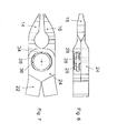
- the two pliers parts 10 and 12 are pivotally connected to each other by a hinge, which is subsequently based on the FIGS. 2 to 7 will be explained in detail.
- the joint is inserted as Joint formed in which the joint portions 22 and 24 each have milled recesses into which the corresponding hinge portion 22 and 24 of the other pliers part 10 and 12 is inserted. It is obvious that the joint can also be designed as an applied joint.
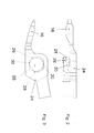
- FIGS. 2 and 3 the hinge portion 24 of the second pliers member 12 is shown.
- pin 26 is formed at the joint area 24 a directed against the hinge portion 22 of the first pliers member 10 .
- the pin 26 has the shape of a straight circular cylinder whose central axis coincides with the pivot axis of the pliers.
- a peripheral collar 28 is integrally formed on the outer circumference thereof.
- the peripheral collar is milled on two diametrically opposite sides, so that parallel to the longitudinal extent of the pliers part 12 extending flat sides 30 result. The milling is performed up to the diameter of the pin 26, so that the flat sides 30 have a diameter of the pin 26 corresponding distance.
- the circumferential collar thereby forms two diametrically arranged circumferential tabs 28 which protrude in the direction of the longitudinal extent of the pliers part 12 in the distal or proximal direction.
- the axial height of the pin 26 is slightly less than the milled portion 22 of the first pliers member 10 receiving milled portion of the hinge portion 24, as in FIG. 2 is indicated by a dashed line.
- This hinge portion 22 has a bore 32 whose diameter corresponds to the diameter of the pin 26 and whose central axis coincides with the pivot axis of the pliers.
- the bore 32 is formed as a blind bore, whose axial depth is slightly larger than the axial height of the pin 26. In half the depth of the bore 32 is in the inner circumference a circumferential groove 34 incorporated.
- the circumferential groove 34 corresponds in its axial position, in its axial width and in its radial depth in each case the axial position, the axial width and the radial height of the peripheral tabs 28 of the pin 26.
- the Diameter of the bore 32 extends on two diametrical sides into the circumferential groove 34 into the outer diameter of the circumferential groove 34.
- two entrance grooves 36 are formed, which lead from the surface of the hinge portion 22 into the circumferential groove 34 and correspond in cross-sectional shape and the cross-sectional dimensions of the circumferential tabs 28 of the second pliers member 12.
- the entrance grooves 36 are aligned so that they are perpendicular to the longitudinal extent of the pliers part 10.
- the two pliers parts 10 and 12 are arranged with their longitudinal axes perpendicular to each other.
- the circumferential tabs 28 come in their angular position with the inlet channels 36 to cover.
- the pin 26 can now be inserted axially into the bore 32, wherein the circumferential tabs 28 passes through the kitrinnen 36 in the axial region of the circumferential groove 34.
- the pliers parts 10 and 12 are pivoted in the closing direction against each other.
- the circumferential tabs 28 are rotated relative to the inlet grooves 36 and enter the circumferential groove 34.
- the pliers are ready for use.
- the pin 26 is rotatably guided in the bore 32 and is held by the engaging in the circumferential groove 34 circumferential tabs 28 in the axial direction positively in the bore 32.
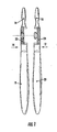
- the bore 32 can also be formed as a through hole, as shown in FIG. 1 is shown.
- the formation of the bore 23 as a blind hole has the advantage that the joint is visible neither from the outside of the hinge portion 22 nor from the outside of the hinge portion 24.
- a brake insert 38 is inserted into the joint.
- the brake pad 38 may be made of a suitable material such as a plastic having a defined elasticity and lubricity in mating with the metal of the hinge portions 22 and 24, respectively.
- the brake insert 38 can be used for example in one of the axial end faces of the circumferential groove 34 so that it occurs in braking action with the peripheral tabs 28 of the pin. Is the bore 32 formed as a blind bore, as in the FIGS.
- the brake pad 38 is preferably arranged as a circular disc at the bottom of the bore 32 so that it occurs in braking action with the axial end face of the pin 26; like this in FIG. 6 is indicated.
- circumferential tab 28 instead of two diametrical circumferential tabs 28, only one radially projecting circumferential tabs can be provided, whereby correspondingly only one inlet channel 36 is provided.
- the arrangement of the circumferential tab 28 and the entrance trough 36 is aligned so that the cross-sectional area of the circumferential tabs 28 with the cross-sectional area of the entrance trough 36 then to cover comes when the pliers parts 10 and 12 are aligned according to a maximum opening spread of the pliers.
- any other pivotal position of the circumferential tabs 28 engages in the circumferential groove 34, so that the pin 26 is axially positively held in the bore 32 and thus the pliers parts 10 and 12 are pivotally connected to each other.
- the jaw 14 with the hinge portion 22 and the jaw 16 with the hinge portion 24 are each made as a one-piece part of a suitable metal, in particular a suitable steel. These parts are made especially by milling, turning and drilling. The material used and the manufacturing processes ensure optimum precision and strength in the parts which are essential for the use of the forceps, namely the forceps jaw and the joint.
- the grip legs 18 and 20 are made as separate workpieces.
- the grip legs 18 and 20 are fixedly connected to the respective hinge portions 22 and 24, respectively.
- the grip legs 18 and 20 can be dovetailed, soldered or glued to the joint areas 22 and 24. Since there is no need to set such high demands on precision and material properties on the gripper handle formed by the gripping legs 18 and 20, the selection of the material and the manufacturing method for the gripping legs 18 and 20 can be made from the viewpoint of the most favorable manufacturing cost.
- FIG. 8 shows the pliers in the in FIG. 1 illustrated embodiment.
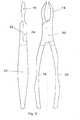
- FIG. 9 shows a pair of pliers with the same forceps jaw as the pliers of the FIG. 8 However, the grip legs 18 and 20 are formed differently.
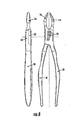
- FIG. 10 shows a pair of pliers, with a bent jaw mouth, which is combined with gripping arms 18 and 20, the handle legs 18 and 20 of the embodiment of the FIG. 9 correspond.
- FIG. 11 shows a pair of pliers with an angled forceps jaw and another angled version of the gripping arms 18 and 20.
Landscapes
- Health & Medical Sciences (AREA)
- Life Sciences & Earth Sciences (AREA)
- Veterinary Medicine (AREA)
- Surgery (AREA)
- Public Health (AREA)
- Animal Behavior & Ethology (AREA)
- General Health & Medical Sciences (AREA)
- Dentistry (AREA)
- Oral & Maxillofacial Surgery (AREA)
- Ophthalmology & Optometry (AREA)
- Nuclear Medicine, Radiotherapy & Molecular Imaging (AREA)
- Epidemiology (AREA)
- Engineering & Computer Science (AREA)
- Biomedical Technology (AREA)
- Heart & Thoracic Surgery (AREA)
- Medical Informatics (AREA)
- Molecular Biology (AREA)
- Dental Tools And Instruments Or Auxiliary Dental Instruments (AREA)
- Dental Preparations (AREA)
Claims (13)
- Pince dentaire comportant deux parties de pinces ayant chacune un mors pour la boucle de la pince ainsi qu'une branche de préhension pour la poignée, les deux parties étant reliées l'une à l'autre, de manière articulée en pivotement,
* l'articulation comprend un goujon (26) cylindrique circulaire coaxial à l'axe de pivotement sur une partie de pince (12) qui pénètre dans un perçage cylindrique circulaire (32) coaxial à l'axe de pivotement, de même diamètre, réalisé dans l'autre partie de pince (10) et tourne dans ce perçage (32) autour de l'axe de pivotement,
* le goujon (26) et le perçage (32) ayant au moins une collerette périphérique (28) et une rainure périphérique de réception (34) s'interpénétrant par la forme dans la direction axiale,
* la collerette périphérique (28) n'occupe qu'une fraction angulaire de la périphérie, et
* au moins une gorge d'entrée (36) ayant une forme de section correspondant à celle de la collerette périphérique (28) conduit axialement à la rainure périphérique (34),
* la collerette périphérique (28) et la gorge périphérique (36) dans la zone d'articulation respective (22 ou 24) sont alignées dans leur disposition angulaire de façon que dans la position d'écartement en ouverture maximale des parties de pinces (10, 12), elles se chevauchent et que l'arête périphérique (28) s'introduise à travers une gorge d'entrée (36) dans la rainure périphérique (34) ou puisse être dégagée de celle-ci, alors que dans les autres positions d'écartement des parties de pinces (10, 12), la collerette périphérique (28) pénètre dans la rainure périphérique (34) et y est maintenue axialement par une liaison par la forme. - Pince selon la revendication 1,
caractérisée en ce que
l'articulation est une articulation intégrée. - Pince selon la revendication 1 ou 2,
caractérisée en ce qu'
au moins une collerette périphérique (28) est réalisée sur le goujon (26) et la rainure périphérique (34) est réalisée dans le perçage (32). - Pince selon l'une des revendications 1 à 3,
caractérisée en ce que
la position angulaire d'au moins une collerette périphérique (28) et celle d'au moins une gorge d'entrée (36) dans les zones d'articulation respectives (22, 24) sont alignées de façon à coïncider lorsque les parties de pinces (10, 12) sont mises dans un angle d'écartement d'ouverture maximum d'environ 90°. - Pince selon l'une des revendications 1 à 4,
caractérisée par
deux collerettes périphériques (28) diamétralement opposées et deux gorges d'entrée (36) diamétralement opposées. - Pince selon l'une des revendications 1 à 5,
caractérisée en ce que
le perçage (32) est traversant. - Pince selon l'une des revendications 1 à 5,
caractérisée en ce que
le perçage (32) est un perçage borgne avec un fond fermé. - Pince selon l'une des revendications 1 à 7,
caractérisée par
un insert de frein (38) interposé entre la paroi du perçage (32) et la paroi du goujon (26). - Pince selon les revendications 7 et 8,
caractérisée en ce que
l'insert de frein (38) est placé entre le fond du perçage (32) et la surface frontale axiale du goujon (26). - Pince selon l'une des revendications 1 à 9,
caractérisée en ce que
les parties de pinces (10, 12) sont réalisées respectivement en deux morceaux, à savoir une branche de poignée (18, 20) constituant l'un des morceaux et un morceau formant la zone d'articulation (22, 24) et le mors (14, 16), et en ce que les deux morceaux sont reliés solidairement l'un à l'autre. - Pince selon la revendication 10,
caractérisée en ce que
les deux morceaux sont réunis par un goujon, par une soudure ou par un collage. - Pince selon la revendication 10 ou 11,
caractérisée en ce que
le morceau formant la zone d'articulation (22, 24) et le mors (14, 16) est réalisé par fraisage, travail au tour, perçage ou injection. - Pince selon l'une des revendications 10 à 12,
caractérisée en ce que
les deux morceaux sont réalisés en des matériaux différents.
Priority Applications (1)
| Application Number | Priority Date | Filing Date | Title |
|---|---|---|---|
| PL05001310T PL1566151T3 (pl) | 2004-02-19 | 2005-01-24 | Kleszcze stomatologiczne z rozłącznymi połówkami |
Applications Claiming Priority (2)
| Application Number | Priority Date | Filing Date | Title |
|---|---|---|---|
| DE202004002560U | 2004-02-19 | ||
| DE202004002560U DE202004002560U1 (de) | 2004-02-19 | 2004-02-19 | Dentalmedizinische Zange |
Publications (3)
| Publication Number | Publication Date |
|---|---|
| EP1566151A2 EP1566151A2 (fr) | 2005-08-24 |
| EP1566151A3 EP1566151A3 (fr) | 2006-04-05 |
| EP1566151B1 true EP1566151B1 (fr) | 2011-10-12 |
Family
ID=32186281
Family Applications (1)
| Application Number | Title | Priority Date | Filing Date |
|---|---|---|---|
| EP05001310A Expired - Lifetime EP1566151B1 (fr) | 2004-02-19 | 2005-01-24 | Forceps dentaire composé de deux moitiés séparables |
Country Status (5)
| Country | Link |
|---|---|
| US (1) | US7318725B2 (fr) |
| EP (1) | EP1566151B1 (fr) |
| AT (1) | ATE527956T1 (fr) |
| DE (1) | DE202004002560U1 (fr) |
| PL (1) | PL1566151T3 (fr) |
Families Citing this family (20)
| Publication number | Priority date | Publication date | Assignee | Title |
|---|---|---|---|---|
| US9687315B2 (en) | 2002-11-27 | 2017-06-27 | Beak And Bumper, Llc | Dental plier design with offsetting jaw and pad elements for assisting in removing upper and lower teeth utilizing the dental plier design |
| US9655689B2 (en) * | 2005-03-31 | 2017-05-23 | Beak And Bumper, Llc | Forceps for molar extraction |
| US20110027754A1 (en) * | 2005-03-31 | 2011-02-03 | Richard Golden | Dental pliers with adjustable bumper |
| US8152834B2 (en) * | 2005-04-13 | 2012-04-10 | Synthes Usa, Llc | Forceps and system using same |
| CA2662858A1 (fr) * | 2005-09-23 | 2007-04-05 | Bruns Daniel Kidd | Outil de sertissage de tubes non metalliques sur des raccords |
| FR2905257B1 (fr) * | 2006-09-05 | 2009-04-03 | Landanger Sa | Articulation pour instrumentation chirurgicale. |
| SE531737C2 (sv) * | 2006-12-01 | 2009-07-28 | Sundtorp Innovation Ab | Skruvlås för isärtagbara kirurgiska instrument |
| WO2008097954A1 (fr) * | 2007-02-05 | 2008-08-14 | Richard Golden | Dispositif d'extraction buccale à une seule poignée |
| US7967602B2 (en) * | 2008-10-07 | 2011-06-28 | John Theodore Lindquist | Pliers for forming orthodontic wires |
| WO2011126550A2 (fr) | 2010-03-31 | 2011-10-13 | Goodman Phillip M | Phase de serrage orthodontique |
| US8210845B1 (en) * | 2011-05-04 | 2012-07-03 | Luis Ingels | Orthodontic pliers |
| US8968306B2 (en) | 2011-08-09 | 2015-03-03 | Covidien Lp | Surgical forceps |
| US20140373689A1 (en) * | 2012-01-10 | 2014-12-25 | Coltene Whaledent Inc. | Hand tool joint |
| US9173719B2 (en) | 2013-11-08 | 2015-11-03 | Beak And Bumper, Llc | Force applying attachment, kit and method for pre-loosening a tooth in order to facilitate removal thereof |
| US9974602B2 (en) | 2015-05-27 | 2018-05-22 | Covidien Lp | Surgical instruments and devices and methods facilitating the manufacture of the same |
| CN107349020A (zh) * | 2016-05-10 | 2017-11-17 | 上海伟荣医疗器材有限公司 | 一种穿腮式拔牙钳 |
| DE102016116623A1 (de) * | 2016-09-06 | 2018-03-08 | Karl Leibinger Medizintechnik Gmbh & Co. Kg | Werkzeuglos montierbares/demontierbares medizinisches Instrument |
| DE102017109125A1 (de) | 2017-04-27 | 2018-10-31 | Aesculap Ag | Chirurgisches Instrument der zwei Branchen-Bauart mit verbesserter Reinigungseignung |
| CN108577932B (zh) * | 2018-05-21 | 2020-10-30 | 王国伟 | 一种骨科多功能手术钳 |
| US11376030B2 (en) | 2020-02-10 | 2022-07-05 | Covidien Lp | Devices and methods facilitating the manufacture of surgical instruments |
Family Cites Families (16)
| Publication number | Priority date | Publication date | Assignee | Title |
|---|---|---|---|---|
| US1159621A (en) * | 1915-11-09 | H D Smith & Company | Pliers and similar tool. | |
| US918672A (en) * | 1907-01-29 | 1909-04-20 | Rasmus P Hansen | Compound tool. |
| FR401954A (fr) * | 1909-04-10 | 1909-09-23 | Marguerite Leontine Bernard | Davier élévateur |
| DE743853C (de) * | 1939-03-11 | 1944-01-04 | Alois Hipp | Loesbares Gelenk fuer chirurgische Instrumente o. dgl. |
| US2632661A (en) * | 1948-08-14 | 1953-03-24 | Cristofv Cristjo | Joint for surgical instruments |
| US3735763A (en) * | 1967-01-10 | 1973-05-29 | Amp Inc | Hemostat |
| GB1432843A (en) * | 1973-04-04 | 1976-04-22 | Rommel Reiner | Tongs |
| GB1464580A (en) * | 1974-05-20 | 1977-02-16 | Happenden Richborough Ltd | Plastics forceps hinge |
| US4662372A (en) * | 1985-08-12 | 1987-05-05 | Acme United Corporation | Disposable surgical instrument and method of forming |
| US4962372A (en) * | 1989-05-30 | 1990-10-09 | Swier Eugene L | Self limiting cable supervisory device |
| US5197879A (en) * | 1991-09-06 | 1993-03-30 | Fowler Iii Hudson D | Orthodontic, medical, dental tool |
| US5232360A (en) * | 1991-09-16 | 1993-08-03 | Luis Ingels | Orthodontic pliers |
| DE19705343C1 (de) * | 1997-02-12 | 1998-02-12 | Liou Mou Tang | Zange mit integriertem Drehzapfen |
| US6000941A (en) * | 1998-11-18 | 1999-12-14 | Ingels; Luis | Separable orthodontic pliers |
| US6370991B1 (en) * | 2000-12-04 | 2002-04-16 | Shih-Kuei Hsieh | Pliers for use in narrow space |
| US20040166475A1 (en) * | 2003-02-24 | 2004-08-26 | George Nikolov | Sterilizable dental and surgical instrument |
-
2004
- 2004-02-19 DE DE202004002560U patent/DE202004002560U1/de not_active Expired - Lifetime
-
2005
- 2005-01-24 AT AT05001310T patent/ATE527956T1/de active
- 2005-01-24 PL PL05001310T patent/PL1566151T3/pl unknown
- 2005-01-24 EP EP05001310A patent/EP1566151B1/fr not_active Expired - Lifetime
- 2005-02-16 US US11/059,591 patent/US7318725B2/en not_active Expired - Fee Related
Also Published As
| Publication number | Publication date |
|---|---|
| ATE527956T1 (de) | 2011-10-15 |
| PL1566151T3 (pl) | 2012-03-30 |
| US7318725B2 (en) | 2008-01-15 |
| US20050186536A1 (en) | 2005-08-25 |
| DE202004002560U1 (de) | 2004-04-22 |
| EP1566151A3 (fr) | 2006-04-05 |
| EP1566151A2 (fr) | 2005-08-24 |
Similar Documents
| Publication | Publication Date | Title |
|---|---|---|
| EP1566151A2 (fr) | Pince pour applications dentaires et médicales | |
| DE102010025653B4 (de) | Rotations-Schneidwerkzeug | |
| DE19722062C2 (de) | Zerlegbares medizinisches Instrument mit selbstorientierender Kupplung | |
| EP0302992B1 (fr) | Mandrin à reserrage | |
| DE69927245T2 (de) | Schraubenschlüssel mit drehmomentanzeige | |
| DE102004032941B4 (de) | Klemmring und Rohrverbindung | |
| DE4343013C2 (de) | Bohrhammer mit einer Kombinations-Werkzeughalterung | |
| EP2261447B1 (fr) | Cadenas | |
| DE10101440A1 (de) | Preßzange | |
| DE2732677C3 (de) | Spannzange | |
| EP3528688A1 (fr) | Dispositif médical | |
| DE4407668A1 (de) | Chirurgisches Anastomosenring-Setzgerät | |
| DE10043445A1 (de) | Verriegelungs-Spannfutter | |
| EP0820734B1 (fr) | Pièce à main angulaire ou droite avec dispositif de serrage détachable pour un outil rotatif, en particulier pour des fins médicales ou dentaires | |
| EP1240963A1 (fr) | Elément de raccord | |
| EP4103357B1 (fr) | Pince | |
| EP3313619B1 (fr) | Pince munie de deux branches se croisant dans un tourillon d'articulation | |
| EP3784439A1 (fr) | Pince | |
| EP1378207B1 (fr) | Pièce à main medicale ou dentaire avec un bouton-poussoir pour le désaccouplement d'un outil | |
| EP3097873B1 (fr) | Outil pour un instrument medical demontable | |
| EP1709931B1 (fr) | Organe moteur, en particulier pièce à main dentaire avec un accouplement détachable pour un porte-outil | |
| EP3614937B1 (fr) | Instrument chirurgical de construction à deux branches avec facilité de nettoyage améliorée | |
| DE4424493C2 (de) | Zangenartiges Werkzeug zum formschlüssigen Verbinden von Blechteilen | |
| EP2769109A1 (fr) | Dispositif d'assemblage et procédé de fabrication dudit dispositif | |
| DE102011002663A1 (de) | Fräswerkzeug, insbesondere zum Befräsen von Elekrodenspitzen von Punktschweißelektroden |
Legal Events
| Date | Code | Title | Description |
|---|---|---|---|
| PUAI | Public reference made under article 153(3) epc to a published international application that has entered the european phase |
Free format text: ORIGINAL CODE: 0009012 |
|
| AK | Designated contracting states |
Kind code of ref document: A2 Designated state(s): AT BE BG CH CY CZ DE DK EE ES FI FR GB GR HU IE IS IT LI LT LU MC NL PL PT RO SE SI SK TR |
|
| AX | Request for extension of the european patent |
Extension state: AL BA HR LV MK YU |
|
| RIC1 | Information provided on ipc code assigned before grant |
Ipc: A61B 17/28 19680901ALI20051119BHEP Ipc: A61C 3/14 19680901AFI20050530BHEP |
|
| PUAL | Search report despatched |
Free format text: ORIGINAL CODE: 0009013 |
|
| AK | Designated contracting states |
Kind code of ref document: A3 Designated state(s): AT BE BG CH CY CZ DE DK EE ES FI FR GB GR HU IE IS IT LI LT LU MC NL PL PT RO SE SI SK TR |
|
| AX | Request for extension of the european patent |
Extension state: AL BA HR LV MK YU |
|
| 17P | Request for examination filed |
Effective date: 20060624 |
|
| AKX | Designation fees paid |
Designated state(s): AT BE BG CH CY CZ DE DK EE ES FI FR GB GR HU IE IS IT LI LT LU MC NL PL PT RO SE SI SK TR |
|
| 17Q | First examination report despatched |
Effective date: 20080130 |
|
| RTI1 | Title (correction) |
Free format text: DENTAL FORCEPS WITH SEPARABLE HALVES |
|
| GRAP | Despatch of communication of intention to grant a patent |
Free format text: ORIGINAL CODE: EPIDOSNIGR1 |
|
| GRAS | Grant fee paid |
Free format text: ORIGINAL CODE: EPIDOSNIGR3 |
|
| GRAA | (expected) grant |
Free format text: ORIGINAL CODE: 0009210 |
|
| AK | Designated contracting states |
Kind code of ref document: B1 Designated state(s): AT BE BG CH CY CZ DE DK EE ES FI FR GB GR HU IE IS IT LI LT LU MC NL PL PT RO SE SI SK TR |
|
| REG | Reference to a national code |
Ref country code: GB Ref legal event code: FG4D Free format text: NOT ENGLISH |
|
| REG | Reference to a national code |
Ref country code: CH Ref legal event code: EP |
|
| REG | Reference to a national code |
Ref country code: IE Ref legal event code: FG4D |
|
| REG | Reference to a national code |
Ref country code: DE Ref legal event code: R096 Ref document number: 502005011991 Country of ref document: DE Effective date: 20111215 |
|
| REG | Reference to a national code |
Ref country code: SE Ref legal event code: TRGR |
|
| REG | Reference to a national code |
Ref country code: CH Ref legal event code: NV Representative=s name: R. A. EGLI & CO. PATENTANWAELTE |
|
| REG | Reference to a national code |
Ref country code: NL Ref legal event code: T3 |
|
| LTIE | Lt: invalidation of european patent or patent extension |
Effective date: 20111012 |
|
| REG | Reference to a national code |
Ref country code: PL Ref legal event code: T3 |
|
| PG25 | Lapsed in a contracting state [announced via postgrant information from national office to epo] |
Ref country code: IS Free format text: LAPSE BECAUSE OF FAILURE TO SUBMIT A TRANSLATION OF THE DESCRIPTION OR TO PAY THE FEE WITHIN THE PRESCRIBED TIME-LIMIT Effective date: 20120212 Ref country code: LT Free format text: LAPSE BECAUSE OF FAILURE TO SUBMIT A TRANSLATION OF THE DESCRIPTION OR TO PAY THE FEE WITHIN THE PRESCRIBED TIME-LIMIT Effective date: 20111012 |
|
| REG | Reference to a national code |
Ref country code: IE Ref legal event code: FD4D |
|
| PG25 | Lapsed in a contracting state [announced via postgrant information from national office to epo] |
Ref country code: GR Free format text: LAPSE BECAUSE OF FAILURE TO SUBMIT A TRANSLATION OF THE DESCRIPTION OR TO PAY THE FEE WITHIN THE PRESCRIBED TIME-LIMIT Effective date: 20120113 Ref country code: SI Free format text: LAPSE BECAUSE OF FAILURE TO SUBMIT A TRANSLATION OF THE DESCRIPTION OR TO PAY THE FEE WITHIN THE PRESCRIBED TIME-LIMIT Effective date: 20111012 Ref country code: PT Free format text: LAPSE BECAUSE OF FAILURE TO SUBMIT A TRANSLATION OF THE DESCRIPTION OR TO PAY THE FEE WITHIN THE PRESCRIBED TIME-LIMIT Effective date: 20120213 |
|
| PGFP | Annual fee paid to national office [announced via postgrant information from national office to epo] |
Ref country code: TR Payment date: 20120124 Year of fee payment: 8 |
|
| PG25 | Lapsed in a contracting state [announced via postgrant information from national office to epo] |
Ref country code: CY Free format text: LAPSE BECAUSE OF FAILURE TO SUBMIT A TRANSLATION OF THE DESCRIPTION OR TO PAY THE FEE WITHIN THE PRESCRIBED TIME-LIMIT Effective date: 20111012 |
|
| PG25 | Lapsed in a contracting state [announced via postgrant information from national office to epo] |
Ref country code: BG Free format text: LAPSE BECAUSE OF FAILURE TO SUBMIT A TRANSLATION OF THE DESCRIPTION OR TO PAY THE FEE WITHIN THE PRESCRIBED TIME-LIMIT Effective date: 20120112 Ref country code: CZ Free format text: LAPSE BECAUSE OF FAILURE TO SUBMIT A TRANSLATION OF THE DESCRIPTION OR TO PAY THE FEE WITHIN THE PRESCRIBED TIME-LIMIT Effective date: 20111012 Ref country code: IE Free format text: LAPSE BECAUSE OF FAILURE TO SUBMIT A TRANSLATION OF THE DESCRIPTION OR TO PAY THE FEE WITHIN THE PRESCRIBED TIME-LIMIT Effective date: 20111012 Ref country code: SK Free format text: LAPSE BECAUSE OF FAILURE TO SUBMIT A TRANSLATION OF THE DESCRIPTION OR TO PAY THE FEE WITHIN THE PRESCRIBED TIME-LIMIT Effective date: 20111012 Ref country code: EE Free format text: LAPSE BECAUSE OF FAILURE TO SUBMIT A TRANSLATION OF THE DESCRIPTION OR TO PAY THE FEE WITHIN THE PRESCRIBED TIME-LIMIT Effective date: 20111012 Ref country code: DK Free format text: LAPSE BECAUSE OF FAILURE TO SUBMIT A TRANSLATION OF THE DESCRIPTION OR TO PAY THE FEE WITHIN THE PRESCRIBED TIME-LIMIT Effective date: 20111012 |
|
| PLBE | No opposition filed within time limit |
Free format text: ORIGINAL CODE: 0009261 |
|
| STAA | Information on the status of an ep patent application or granted ep patent |
Free format text: STATUS: NO OPPOSITION FILED WITHIN TIME LIMIT |
|
| PG25 | Lapsed in a contracting state [announced via postgrant information from national office to epo] |
Ref country code: RO Free format text: LAPSE BECAUSE OF FAILURE TO SUBMIT A TRANSLATION OF THE DESCRIPTION OR TO PAY THE FEE WITHIN THE PRESCRIBED TIME-LIMIT Effective date: 20111012 Ref country code: MC Free format text: LAPSE BECAUSE OF NON-PAYMENT OF DUE FEES Effective date: 20120131 |
|
| 26N | No opposition filed |
Effective date: 20120713 |
|
| REG | Reference to a national code |
Ref country code: DE Ref legal event code: R097 Ref document number: 502005011991 Country of ref document: DE Effective date: 20120713 |
|
| PG25 | Lapsed in a contracting state [announced via postgrant information from national office to epo] |
Ref country code: ES Free format text: LAPSE BECAUSE OF FAILURE TO SUBMIT A TRANSLATION OF THE DESCRIPTION OR TO PAY THE FEE WITHIN THE PRESCRIBED TIME-LIMIT Effective date: 20120123 |
|
| PGFP | Annual fee paid to national office [announced via postgrant information from national office to epo] |
Ref country code: NL Payment date: 20130121 Year of fee payment: 9 Ref country code: PL Payment date: 20130124 Year of fee payment: 9 |
|
| PG25 | Lapsed in a contracting state [announced via postgrant information from national office to epo] |
Ref country code: FI Free format text: LAPSE BECAUSE OF FAILURE TO SUBMIT A TRANSLATION OF THE DESCRIPTION OR TO PAY THE FEE WITHIN THE PRESCRIBED TIME-LIMIT Effective date: 20111012 |
|
| PGFP | Annual fee paid to national office [announced via postgrant information from national office to epo] |
Ref country code: SE Payment date: 20140123 Year of fee payment: 10 Ref country code: CH Payment date: 20140124 Year of fee payment: 10 Ref country code: BE Payment date: 20140122 Year of fee payment: 10 |
|
| PG25 | Lapsed in a contracting state [announced via postgrant information from national office to epo] |
Ref country code: LU Free format text: LAPSE BECAUSE OF NON-PAYMENT OF DUE FEES Effective date: 20120124 |
|
| PGFP | Annual fee paid to national office [announced via postgrant information from national office to epo] |
Ref country code: FR Payment date: 20140124 Year of fee payment: 10 Ref country code: IT Payment date: 20140129 Year of fee payment: 10 Ref country code: AT Payment date: 20140122 Year of fee payment: 10 |
|
| PGFP | Annual fee paid to national office [announced via postgrant information from national office to epo] |
Ref country code: GB Payment date: 20140123 Year of fee payment: 10 |
|
| PG25 | Lapsed in a contracting state [announced via postgrant information from national office to epo] |
Ref country code: HU Free format text: LAPSE BECAUSE OF FAILURE TO SUBMIT A TRANSLATION OF THE DESCRIPTION OR TO PAY THE FEE WITHIN THE PRESCRIBED TIME-LIMIT Effective date: 20050124 |
|
| REG | Reference to a national code |
Ref country code: NL Ref legal event code: V1 Effective date: 20140801 |
|
| PG25 | Lapsed in a contracting state [announced via postgrant information from national office to epo] |
Ref country code: NL Free format text: LAPSE BECAUSE OF NON-PAYMENT OF DUE FEES Effective date: 20140801 |
|
| REG | Reference to a national code |
Ref country code: PL Ref legal event code: LAPE |
|
| PG25 | Lapsed in a contracting state [announced via postgrant information from national office to epo] |
Ref country code: PL Free format text: LAPSE BECAUSE OF NON-PAYMENT OF DUE FEES Effective date: 20140124 |
|
| PG25 | Lapsed in a contracting state [announced via postgrant information from national office to epo] |
Ref country code: BE Free format text: LAPSE BECAUSE OF NON-PAYMENT OF DUE FEES Effective date: 20150131 |
|
| REG | Reference to a national code |
Ref country code: CH Ref legal event code: PL |
|
| REG | Reference to a national code |
Ref country code: SE Ref legal event code: EUG |
|
| REG | Reference to a national code |
Ref country code: AT Ref legal event code: MM01 Ref document number: 527956 Country of ref document: AT Kind code of ref document: T Effective date: 20150124 |
|
| GBPC | Gb: european patent ceased through non-payment of renewal fee |
Effective date: 20150124 |
|
| PG25 | Lapsed in a contracting state [announced via postgrant information from national office to epo] |
Ref country code: TR Free format text: LAPSE BECAUSE OF NON-PAYMENT OF DUE FEES Effective date: 20130124 |
|
| PG25 | Lapsed in a contracting state [announced via postgrant information from national office to epo] |
Ref country code: CH Free format text: LAPSE BECAUSE OF NON-PAYMENT OF DUE FEES Effective date: 20150131 Ref country code: GB Free format text: LAPSE BECAUSE OF NON-PAYMENT OF DUE FEES Effective date: 20150124 Ref country code: LI Free format text: LAPSE BECAUSE OF NON-PAYMENT OF DUE FEES Effective date: 20150131 |
|
| REG | Reference to a national code |
Ref country code: FR Ref legal event code: ST Effective date: 20150930 |
|
| PG25 | Lapsed in a contracting state [announced via postgrant information from national office to epo] |
Ref country code: AT Free format text: LAPSE BECAUSE OF NON-PAYMENT OF DUE FEES Effective date: 20150124 Ref country code: FR Free format text: LAPSE BECAUSE OF NON-PAYMENT OF DUE FEES Effective date: 20150202 Ref country code: SE Free format text: LAPSE BECAUSE OF NON-PAYMENT OF DUE FEES Effective date: 20150125 |
|
| PG25 | Lapsed in a contracting state [announced via postgrant information from national office to epo] |
Ref country code: IT Free format text: LAPSE BECAUSE OF NON-PAYMENT OF DUE FEES Effective date: 20150124 |
|
| PGFP | Annual fee paid to national office [announced via postgrant information from national office to epo] |
Ref country code: DE Payment date: 20240226 Year of fee payment: 20 |
|
| REG | Reference to a national code |
Ref country code: DE Ref legal event code: R071 Ref document number: 502005011991 Country of ref document: DE |