EP1564985B1 - Vorrichtung zur digitalen Abtastung von farbigen Bildvorlagen - Google Patents
Vorrichtung zur digitalen Abtastung von farbigen Bildvorlagen Download PDFInfo
- Publication number
- EP1564985B1 EP1564985B1 EP05090004A EP05090004A EP1564985B1 EP 1564985 B1 EP1564985 B1 EP 1564985B1 EP 05090004 A EP05090004 A EP 05090004A EP 05090004 A EP05090004 A EP 05090004A EP 1564985 B1 EP1564985 B1 EP 1564985B1
- Authority
- EP
- European Patent Office
- Prior art keywords
- tdi
- light source
- sensor
- light
- original
- Prior art date
- Legal status (The legal status is an assumption and is not a legal conclusion. Google has not performed a legal analysis and makes no representation as to the accuracy of the status listed.)
- Expired - Lifetime
Links
Images

Classifications
-
- H—ELECTRICITY
- H04—ELECTRIC COMMUNICATION TECHNIQUE
- H04N—PICTORIAL COMMUNICATION, e.g. TELEVISION
- H04N1/00—Scanning, transmission or reproduction of documents or the like, e.g. facsimile transmission; Details thereof
- H04N1/46—Colour picture communication systems
- H04N1/48—Picture signal generators
- H04N1/482—Picture signal generators using the same detector device sequentially for different colour components
- H04N1/484—Picture signal generators using the same detector device sequentially for different colour components with sequential colour illumination of the original
-
- H—ELECTRICITY
- H04—ELECTRIC COMMUNICATION TECHNIQUE
- H04N—PICTORIAL COMMUNICATION, e.g. TELEVISION
- H04N23/00—Cameras or camera modules comprising electronic image sensors; Control thereof
- H04N23/80—Camera processing pipelines; Components thereof
- H04N23/84—Camera processing pipelines; Components thereof for processing colour signals
-
- H—ELECTRICITY
- H04—ELECTRIC COMMUNICATION TECHNIQUE
- H04N—PICTORIAL COMMUNICATION, e.g. TELEVISION
- H04N25/00—Circuitry of solid-state image sensors [SSIS]; Control thereof
- H04N25/10—Circuitry of solid-state image sensors [SSIS]; Control thereof for transforming different wavelengths into image signals
- H04N25/11—Arrangement of colour filter arrays [CFA]; Filter mosaics
- H04N25/13—Arrangement of colour filter arrays [CFA]; Filter mosaics characterised by the spectral characteristics of the filter elements
- H04N25/134—Arrangement of colour filter arrays [CFA]; Filter mosaics characterised by the spectral characteristics of the filter elements based on three different wavelength filter elements
-
- H—ELECTRICITY
- H04—ELECTRIC COMMUNICATION TECHNIQUE
- H04N—PICTORIAL COMMUNICATION, e.g. TELEVISION
- H04N3/00—Scanning details of television systems; Combination thereof with generation of supply voltages
- H04N3/36—Scanning of motion picture films, e.g. for telecine
- H04N3/38—Scanning of motion picture films, e.g. for telecine with continuously moving film
Definitions
- the invention relates to a device for the digital scanning of colored image templates according to the preamble of claim 1.
- the presently known devices for digitally scanning image templates operate on two basic principles. Either the image to be digitized image is illuminated with a white light source, then a color separation, for example by means of beam splitting and color filters takes place or the illumination already takes place in the spectral colors red, green and blue, the photosensitive sensor can be monochrome.
- a disadvantage of all known methods is that they have a signal proportional to the sampling rate proportional to the noise ratio.
- TDI sensors are known. These have a plurality of lines, which are aligned transversely to the direction of movement of the image original and whose shift clocks are synchronized with the movement. In the process, an image strip is clearly displayed and scanned on the first line. Synchronized to the image movement, the result of the first line is shifted to the second line and the image strip is scanned again and so on. As a result, the signal-to-noise ratio can be significantly improved.
- the TDI principle requires that three separate sensors be used for color image templates. This in turn is relatively expensive.
- a device for digital scanning of colored image templates comprising at least one photosensitive sensor which is movable relative to the image original, wherein the movement is synchronized to scan, and a light source, wherein the photosensitive sensor is designed as a TDI sensor, wherein the light source is formed such that it generates adjacent RGB light stripes, wherein the light stripes extend transversely to the rows of the TDI sensor.
- the light source is designed as a white light source, wherein a correspondingly structured RGB color filter is arranged in front of the sensor.
- the invention is therefore based on the technical problem of providing a device for digital scanning of color image templates, by means of which an improved signal / noise ratio is possible with a small number of photosensitive sensors.
- the photosensitive sensor is designed as a TDI sensor, wherein the light source is designed such that it generates adjacent RGB light stripes, each one light strip illuminates a line of the TDI sensor and the color of the light stripes, synchronized to the shift clocks of the lines TDI sensor, in the order RGB is switchable.
- the light source is designed such that it generates adjacent RGB light stripes, each one light strip illuminates a line of the TDI sensor and the color of the light stripes, synchronized to the shift clocks of the lines TDI sensor, in the order RGB is switchable.
- the light source is formed as an LED matrix, by means of which strip-shaped R, G, and B light stripes can be generated.
- the light source is formed as an LED matrix, by means of which strip-shaped R, G, and B light stripes can be generated.
- triple arrangements per strip of R, G and B LEDs are controlled alternately.
- a static adjustment of R, G and B strips would be conceivable, wherein the LED matrix is moved in synchronism with the shift clocks of the TDI lines.
- the advantage of the alternating control of the triple arrangement is that no masses have to be moved.
- a plurality of such triple LEDs are arranged along a TDI line as a matrix.
- the light source is designed as a white light source with a downstream color LCD matrix, wherein the permeability of the matrix is switched alternately synchronized with the shift clocks of the TDI lines.
- a lens is arranged between the light source and the image original, by means of which the light stripes are imaged on the image original.
- the device is formed with a film stage, via which the image original is movable, wherein the film stage has a slit-shaped light passage.
- a lens is arranged between the film stage and the TDI sensor, by means of which the transilluminated image original is imaged on the TDI sensor or its lines.
- a TDI sensor 1 with TDI lines 2 is shown.
- the accumulated charges of a TDI line 2 are synchronously shifted in cycles from left to right.
- Dashed lines over TDI lines 2 light stripes 3 are shown.
- the TDI lines 2 can be formed almost without spacing, whereas the light stripes do not have to touch, as long as they cover only the respective line.
- the drawn distribution of light stripes 3 is present.
- the image strip which, for example, the first TDI line 2 sees at time T 0 , is always illuminated red at all times.
- the image strip which, for example, the first TDI line 2 sees at time T 0 .
- the device 10 comprising a white light source 11 with parabolic reflector 12 and a first lens 13 for generating parallel white light 14.
- the parallel white light 14 strikes an LCD matrix 15 which is controlled by an electronic control unit 16 in synchronism with the shift clocks of the TDI Sensor 1 is driven, wherein the color of a column of the LCD matrix 15 each changes in the order RGB.
- About another optics 17 are the Light stripe on a moving in the direction T image original 18, for example, a movie, mapped.
- This exposed image section is imaged with the differently colored illuminated light strip by means of a further optical system 19 on the individual lines of the TDI sensor 1. In this case, the light strip is changed synchronously by driving the LCD matrix 15 with the shift clocks of the TDI lines.
- Fig. 3 an alternative embodiment is shown, wherein as the light source, an LED matrix 20 is used, which can alternately generate R-, G- and B-light stripes depending on the control electronics.
- an LED matrix 20 is used, which can alternately generate R-, G- and B-light stripes depending on the control electronics.
Landscapes
- Engineering & Computer Science (AREA)
- Multimedia (AREA)
- Signal Processing (AREA)
- Physics & Mathematics (AREA)
- Spectroscopy & Molecular Physics (AREA)
- Facsimile Scanning Arrangements (AREA)
- Facsimile Heads (AREA)
Description
- Die Erfindung betrifft eine Vorrichtung zur digitalen Abtastung von farbigen Bildvorlagen gemäß dem Oberbegriff des Anspruchs 1.
- Die derzeit bekannten Vorrichtungen zur digitalen Abtastung von Bildvorlagen arbeiten nach zwei grundlegenden Prinzipien. Entweder wird die zu digitalisierende Bildvorlage mit einer Weißlichtquelle beleuchtet, wobei anschließend eine Farbtrennung, beispielsweise mittels Strahlteilen und Farbfiltern, stattfindet oder die Beleuchtung findet schon in den Spektralfarben Rot, Grün und Blau statt, wobei der photosensitive Sensor monochrom sein kann. Nachteilig an allen bekannten Verfahren ist, dass diese ein zur Abtastgeschwindigkeit indirekt proportionales Signal zum Rauschverhältnis aufweisen.
- Zur Verbesserung des Signal/Rauschverhältnisses sind TDI-Sensoren bekannt. Diese weisen eine Vielzahl von Zeilen auf, die quer zur Bewegungsrichtung der Bildvorlage ausgerichtet sind und deren Schiebetakte mit der Bewegung synchronisiert sind. Dabei wird anschaulich ein Bildstreifen auf der ersten Zeile abgebildet und abgetastet. Synchronisiert zur Bildbewegung wird das Ergebnis der ersten Zeile in die zweite Zeile geschoben und der Bildstreifen erneut abgetastet und so weiter. Hierdurch kann das Signal-Rauschverhältnis erheblich verbessert werden. Allerdings bedingt das TDI-Prinzip, dass für farbige Bildvorlagen drei separate Sensoren verwendet werden müssen. Dies wiederum ist relativ aufwendig.
- Aus der
EP 0 796 005 A2 ist eine Vorrichtung zur digitalen Abtastung von farbigen Bildvorlagen bekannt, umfassend mindestens einen photosensitiven Sensor, der relativ zur Bildvorlage bewegbar ist, wobei die Bewegung zur Abtastung synchronisiert ist, und eine Lichtquelle, wobei der photosensitive Sensor als TDI-Sensor ausgebildet ist, wobei die Lichtquelle derart ausgebildet ist, dass diese nebeneinanderliegende RGB-Lichtstreifen erzeugt, wobei die Lichtstreifen quer zu den Zeilen des TDI-Sensors verlaufen. Die Lichtquelle ist dabei als Weißlichtquelle ausgebildet, wobei vor dem Sensor ein entsprechend strukturierter RGB-Farbfilter angeordnet ist. - Der Erfindung liegt daher das technische Problem zugrunde, eine Vorrichtung zur digitalen Abtastung von farbigen Bildvorlagen zu schaffen, mittels derer ein verbessertes Signal/Rauschverhältnis mit einer geringen Anzahl von photosensitiven Sensoren möglich ist.
- Hierzu ist der photosensitive Sensor als TDI-Sensor ausgebildet, wobei die Lichtquelle derart ausgebildet ist, dass diese nebeneinanderliegende RGB-Lichtstreifen erzeugt, wobei jeweils ein Lichtstreifen eine Zeile des TDI-Sensors beleuchtet und die Farbe der Lichtstreifen, synchronisiert zu den Schiebetakten der Zeilen des TDI-Sensors, in der Reihenfolge RGB umschaltbar ist. Hierdurch kann mittels eines panchromatischen TDI-Sensors ein RGB-Bild erzeugt werden, das ein wesentlich besseres Signal/Rauschverhältnis aufweist.
- In einer bevorzugten Ausführungsform ist die Lichtquelle als LED-Matrix ausgebildet, mittels derer streifenförmige R, G, und B-Lichtstreifen erzeugt werden können. Dabei werden vorzugsweise Tripel-Anordnungen je Streifen von R-, G- und B-LEDs wechselweise angesteuert. Denkbar wäre jedoch eine statische Einstellung von R-, G- und B-Streifen, wobei die LED-Matrix synchronisiert zu den Schiebetakten der TDI-Zeilen bewegt wird. Der Vorteil der wechselweisen Ansteuerung der Tripel-Anordnung ist jedoch, dass keine Massen bewegt werden müssen. Vorzugsweise sind eine Vielzahl derartiger Tripel-LEDs entlang einer TDI-Zeile als Matrix angeordnet.
- In einer alternativen Ausführungsform ist die Lichtquelle als Weißlichtquelle mit nachgeschalteter Farb-LCD-Matrix ausgebildet, wobei die Durchlässigkeit der Matrix wechselweise synchronisiert zu den Schiebetakten der TDI-Zeilen umgeschaltet wird.
- Vorzugsweise erfolgt nach vollständiger Abtastung über alle TDI-Zeilen noch eine Phasenkorrektur, um Ortsverschiebungen zu kompensieren. Diese Verschiebungen treten dadurch auf, dass durch die Bewegung jeweils ein Teil des Bildes bereits in den benachbarten Farbkanal wandert.
- Vorzugsweise ist zwischen der Lichtquelle und der Bildvorlage ein Objektiv angeordnet, mittels dessen die Lichtstreifen auf der Bildvorlage abgebildet werden.
- In einer weiteren bevorzugten Ausführungsform ist die Vorrichtung mit einer Filmbühne ausgebildet, über die die Bildvorlage bewegbar ist, wobei die Filmbühne einen spaltförmigen Lichtdurchlass aufweist.
- In einer weiteren bevorzugten Ausführungsform ist zwischen der Filmbühne und dem TDI-Sensor ein Objektiv angeordnet, mittels dessen die durchleuchtete Bildvorlage auf dem TDI-Sensor bzw. dessen Zeilen abgebildet wird.
- Die Erfindung wird nachfolgend anhand eines bevorzugten Ausführungsbeispieles näher erläutert. Die Fig. zeigen:
- Fig. 1
- eine schematische Teilansicht auf einen TDI-Sensor,
- Fig. 2
- eine schematische Darstellung einer Vorrichtung mit LCD-Matrix und
- Fig. 3
- eine schematische Darstellung einer Vorrichtung mit LED-Matrix.
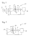
- In der
Fig. 1 ist schematisch ein TDI-Sensor 1 mit TDI-Zeilen 2 dargestellt. Dabei werden die akkumulierten Ladungen einer TDI-Zeile 2 synchron taktweise von links nach rechts verschoben. Gestrichelt über TDI-Zeilen 2 sind Lichtstreifen 3 dargestellt. Dabei sei angemerkt, dass die TDI-Zeilen 2 nahezu ohne Abstand ausgebildet sein können, wohingegen sich die Lichtstreifen nicht berühren müssen, solange diese nur die jeweilige Zeile abdecken. Zu einem Zeitpunkt T0 liegt dabei die eingezeichnete Verteilung von Lichtstreifen 3 vor. Nach einem Schiebetakt der TDI-Zeilen 2 zum Zeitpunkt T1 liegt eine jeweils um eine Farbstufe nach rechts verschobene Lichtstreifen-Verteilung vor. Dadurch wird der Bildstreifen, den beispielsweise die erste TDI-Zeile 2 zum Zeitpunkt T0 sieht, stets zu allen Zeitpunkten rot beleuchtet. Anschaulich kann man sagen, dass so wie sich ein Bildstreifen in Richtung A bewegt der zugehörige Lichtstreifen 3 sich mitbewegt. - In der
Fig. 2 ist schematisch die Vorrichtung 10 dargestellt, umfassend eine Weißlichtquelle 11 mit Parabolreflektor 12 und einem ersten Objektiv 13 zur Erzeugung parallelen weißen Lichtes 14. Das parallele weiße Licht 14 trifft auf eine LCD-Matrix 15, die von einer Steuerelektronik 16 synchron zu den Schiebetakten des TDI-Sensors 1 angesteuert wird, wobei sich die Farbe einer Spalte der LCD-Matrix 15 jeweils in der Reihenfolge RGB ändert. Über eine weitere Optik 17 werden die Lichtstreifen auf eine sich in Richtung T bewegende Bildvorlage 18, beispielsweise einen Film, abgebildet. Dieser belichtete Bildausschnitt wird mit dem verschiedenfarbig beleuchteten Lichtstreifen mittels einer weiteren Optik 19 auf die einzelnen Zeilen des TDI-Sensors 1 abgebildet. Dabei wird synchron der Lichtstreifen durch Ansteuerung der LCD-Matrix 15 mit den Schiebetakten der TDI-Zeilen gewechselt. - In der
Fig. 3 ist eine alternative Ausführungsform dargestellt, wobei als Lichtquelle eine LED-Matrix 20 verwendet wird, die in Abhängigkeit von der Steuerelektronik wechselweise R-, G- und B-Lichtstreifen erzeugen kann. Dabei werden wie bei der Ausführungsform gemäßFig. 2 so viele Lichtstreifen wie TDI-Zeilen vorhanden sind erzeugt, die sich räumlich nach dem Muster RGB und zeitlich nach dem Muster RBG im Schiebetakt der TDI-Zeilen ändern.
Claims (7)
- Vorrichtung zur digitalen Abtastung von farbigen Bildvorlagen, umfassend mindestens einen photosensitiven Sensor, der relativ zur Bildvorlage bewegbar ist, wobei die Bewegung zur Abtastung synchronisiert ist, und mindestens eine Lichtquelle, wobei
der photosensitive Sensor als TDI-Sensor (1) ausgebildet ist, dadurch gekennzeichnet, dass die Lichtquelle derart ausgebildet ist, dass diese nebeneinanderliegende RGB-Lichtstreifen (3) erzeugt, wobei jeweils ein Lichtstreifen (3) eine Zeile (2) des TDI-Sensors (1) beleuchtet und die Farbe der Lichtstreifen (3) synchronisiert zu den Schiebetakten der Zeilen (2) des TDI-Sensors (1) in der Reihenfolge RGB umschaltbar ist. - Vorrichtung nach Anspruch 1, dadurch gekennzeichnet, dass die Lichtquelle als LED-Matrix (20) ausgebildet ist.
- Vorrichtung nach Anspruch 1, dadurch gekennzeichnet, dass die Lichtquelle als Weißlichtquelle (11) mit nachgeschalteter Farb-LCD-Matrix (15) ausgebildet ist.
- Vorrichtung nach einem der vorangegangenen Ansprüche, dadurch gekennzeichnet, dass die ermittelten Farbwerte einer Phasenkorrektur unterworfen werden.
- Vorrichtung nach einem der vorangegangenen Ansprüche, dadurch gekennzeichnet, dass zwischen der Lichtquelle und der Bildvorlage ein Objektiv (17) angeordnet ist.
- Vorrichtung nach einem der vorangegangenen Ansprüche, dadurch gekennzeichnet, dass die Bildvorlage (18) über eine Filmbühne bewegbar ist, in der ein spaltförmiger Lichtdurchlass angeordnet ist.
- Vorrichtung nach Anspruch 6, dadurch gekennzeichnet, dass zwischen der Filmbühne und dem TDI-Sensor (1) ein Objektiv (19) angeordnet ist.
Applications Claiming Priority (2)
| Application Number | Priority Date | Filing Date | Title |
|---|---|---|---|
| DE102004007911A DE102004007911B3 (de) | 2004-02-13 | 2004-02-13 | Vorrichtung zur digitalen Abtastung von farbigen Bildvorlagen |
| DE102004007911 | 2004-02-13 |
Publications (3)
| Publication Number | Publication Date |
|---|---|
| EP1564985A2 EP1564985A2 (de) | 2005-08-17 |
| EP1564985A3 EP1564985A3 (de) | 2007-05-23 |
| EP1564985B1 true EP1564985B1 (de) | 2010-01-20 |
Family
ID=33560438
Family Applications (1)
| Application Number | Title | Priority Date | Filing Date |
|---|---|---|---|
| EP05090004A Expired - Lifetime EP1564985B1 (de) | 2004-02-13 | 2005-01-12 | Vorrichtung zur digitalen Abtastung von farbigen Bildvorlagen |
Country Status (2)
| Country | Link |
|---|---|
| EP (1) | EP1564985B1 (de) |
| DE (2) | DE102004007911B3 (de) |
Families Citing this family (3)
| Publication number | Priority date | Publication date | Assignee | Title |
|---|---|---|---|---|
| DE102006013810B4 (de) * | 2006-03-22 | 2009-06-10 | Martin Langfeld | Verfahren und Vorrichtung zur Bestimmung von Farbinformationen eines Objektabbildes mit Hilfe eines CCD-Bildsensors im TDI-Betriebsmodus |
| DE102009050534A1 (de) | 2009-10-23 | 2011-04-28 | Dft Digital Film Technology Holding Gmbh | Verfahren zum Generieren eines Bildstartpulses bei der Filmabtastung eines während der Filmabtastung in eine Filmlaufrichtung bewegten Films |
| DE102013216764B3 (de) * | 2013-08-23 | 2014-09-04 | BSH Bosch und Siemens Hausgeräte GmbH | Kältegerät mit einem Kameramodul |
Family Cites Families (7)
| Publication number | Priority date | Publication date | Assignee | Title |
|---|---|---|---|---|
| US4264921A (en) * | 1979-06-29 | 1981-04-28 | International Business Machines Corporation | Apparatus for color or panchromatic imaging |
| US5061036A (en) * | 1990-04-17 | 1991-10-29 | Photon Imaging Corp. | Color page scanner using fiber optic bundle and a photosensor array |
| US5101266A (en) * | 1990-12-13 | 1992-03-31 | International Business Machines Corporation | Single-scan time delay and integration color imaging system |
| JPH0576005A (ja) * | 1991-09-13 | 1993-03-26 | Nikon Corp | 画像入力装置 |
| US5481300A (en) * | 1994-04-29 | 1996-01-02 | Motta; Ricardo J. | Image capture system |
| JPH09247545A (ja) * | 1996-03-11 | 1997-09-19 | Matsushita Electric Ind Co Ltd | スキャナ型電子カメラ |
| US6933975B2 (en) * | 2002-04-26 | 2005-08-23 | Fairchild Imaging | TDI imager with automatic speed optimization |
-
2004
- 2004-02-13 DE DE102004007911A patent/DE102004007911B3/de not_active Expired - Lifetime
-
2005
- 2005-01-12 DE DE502005008890T patent/DE502005008890D1/de not_active Expired - Lifetime
- 2005-01-12 EP EP05090004A patent/EP1564985B1/de not_active Expired - Lifetime
Also Published As
| Publication number | Publication date |
|---|---|
| DE502005008890D1 (de) | 2010-03-11 |
| EP1564985A3 (de) | 2007-05-23 |
| EP1564985A2 (de) | 2005-08-17 |
| DE102004007911B3 (de) | 2005-02-03 |
Similar Documents
| Publication | Publication Date | Title |
|---|---|---|
| DE69110229T2 (de) | Anzeigeeinrichtung. | |
| EP2537598B1 (de) | Vorrichtung und Verfahren zur optischen Sortierung von Schüttgut | |
| DE68922957T2 (de) | Verfahren und Anordnung zur Überwachung. | |
| EP3298345B1 (de) | Kamera und verfahren zur dreidimensionalen vermessung und farbvermessung eines dentalen objekts | |
| DE2947791C2 (de) | Einrichtung zur Farbüberwachung von bogen- oder bahnförmigen, in Bewegung befindlichen Materialien, insbesondere der Druckmaterialien von Druckmaschinen | |
| DE3913455C2 (de) | ||
| DE10335190A1 (de) | Sensoranordnung mit einer Mehrzahl von Typen optischer Sensoren | |
| DE2431931A1 (de) | Verfahren und vorrichtung zum bestimmen der versetzung verschiedener teile eines fernsehbildes relativ zueinander | |
| EP1564985B1 (de) | Vorrichtung zur digitalen Abtastung von farbigen Bildvorlagen | |
| DE2559578B2 (de) | Fernsehkamera | |
| WO2010081509A1 (de) | Verfahren und anordnung zur visuellen oberflächeninspektion | |
| DE3688227T2 (de) | Filmuntersuchungsvorrichtung. | |
| DE3203796A1 (de) | Farbvorlagen-lesegeraet | |
| EP0124537A1 (de) | Verfahren zur ueberwachung eines objektraumes. | |
| DE69425425T2 (de) | Farbfernseh-System mit synthetischem Videofarbensystem mit periodischem Farbfilter für die drei Grundfarben | |
| DE3528717A1 (de) | Dynamisches kammfilter zur trennung des leuchtdichte- und farbartsignals eines pal-farbfernsehsignals | |
| AT512220B1 (de) | Verfahren und eine aufnahmevorrichtung zur aufnahme von multispektralbildern | |
| DE10323193A1 (de) | Einrichtung und Verfahren zur multispektralen Abtastung einer Farbbildvorlage | |
| DE102013104060B4 (de) | Verfahren und Vorrichtung zur videografischen Verfolgung von schnell bewegten Objekten | |
| DE2035821C3 (de) | Farbfilmabtaster | |
| DE2853510C2 (de) | Einrichtung zur Herstellung von Farbauszügen insbesondere für den Textildruck | |
| DE102009000344B4 (de) | Verfahren zum Betrieb einer Anordnung mit mehreren Pixeln und Gerät, aufweisend einen Bildsensor | |
| DE102014224554B4 (de) | Verfahren und System zum Erzeugen von digitalen Farbbildern oder Videosequenzen | |
| EP2422980A1 (de) | Vorrichtung zur Farbmessung in einer Rotationsdruckmachine | |
| DE29520865U1 (de) | CCD-Flächensensoren mit Farbmosaik-Filter |
Legal Events
| Date | Code | Title | Description |
|---|---|---|---|
| PUAI | Public reference made under article 153(3) epc to a published international application that has entered the european phase |
Free format text: ORIGINAL CODE: 0009012 |
|
| AK | Designated contracting states |
Kind code of ref document: A2 Designated state(s): AT BE BG CH CY CZ DE DK EE ES FI FR GB GR HU IE IS IT LI LT LU MC NL PL PT RO SE SI SK TR |
|
| AX | Request for extension of the european patent |
Extension state: AL BA HR LV MK YU |
|
| RAP1 | Party data changed (applicant data changed or rights of an application transferred) |
Owner name: DEUTSCHES ZENTRUM FUER LUFT- UND RAUMFAHRT E.V. |
|
| PUAL | Search report despatched |
Free format text: ORIGINAL CODE: 0009013 |
|
| AK | Designated contracting states |
Kind code of ref document: A3 Designated state(s): AT BE BG CH CY CZ DE DK EE ES FI FR GB GR HU IE IS IT LI LT LU MC NL PL PT RO SE SI SK TR |
|
| AX | Request for extension of the european patent |
Extension state: AL BA HR LV MK YU |
|
| 17P | Request for examination filed |
Effective date: 20070622 |
|
| 17Q | First examination report despatched |
Effective date: 20070727 |
|
| AKX | Designation fees paid |
Designated state(s): DE FR GB |
|
| GRAP | Despatch of communication of intention to grant a patent |
Free format text: ORIGINAL CODE: EPIDOSNIGR1 |
|
| GRAS | Grant fee paid |
Free format text: ORIGINAL CODE: EPIDOSNIGR3 |
|
| GRAA | (expected) grant |
Free format text: ORIGINAL CODE: 0009210 |
|
| AK | Designated contracting states |
Kind code of ref document: B1 Designated state(s): DE FR GB |
|
| REG | Reference to a national code |
Ref country code: GB Ref legal event code: FG4D Free format text: NOT ENGLISH |
|
| REF | Corresponds to: |
Ref document number: 502005008890 Country of ref document: DE Date of ref document: 20100311 Kind code of ref document: P |
|
| PLBE | No opposition filed within time limit |
Free format text: ORIGINAL CODE: 0009261 |
|
| STAA | Information on the status of an ep patent application or granted ep patent |
Free format text: STATUS: NO OPPOSITION FILED WITHIN TIME LIMIT |
|
| 26N | No opposition filed |
Effective date: 20101021 |
|
| REG | Reference to a national code |
Ref country code: FR Ref legal event code: PLFP Year of fee payment: 12 |
|
| REG | Reference to a national code |
Ref country code: FR Ref legal event code: PLFP Year of fee payment: 13 |
|
| REG | Reference to a national code |
Ref country code: FR Ref legal event code: PLFP Year of fee payment: 14 |
|
| PGFP | Annual fee paid to national office [announced via postgrant information from national office to epo] |
Ref country code: GB Payment date: 20231218 Year of fee payment: 20 |
|
| PGFP | Annual fee paid to national office [announced via postgrant information from national office to epo] |
Ref country code: FR Payment date: 20231214 Year of fee payment: 20 |
|
| PGFP | Annual fee paid to national office [announced via postgrant information from national office to epo] |
Ref country code: DE Payment date: 20231215 Year of fee payment: 20 |
|
| REG | Reference to a national code |
Ref country code: DE Ref legal event code: R071 Ref document number: 502005008890 Country of ref document: DE |
|
| REG | Reference to a national code |
Ref country code: GB Ref legal event code: PE20 Expiry date: 20250111 |
|
| PG25 | Lapsed in a contracting state [announced via postgrant information from national office to epo] |
Ref country code: GB Free format text: LAPSE BECAUSE OF EXPIRATION OF PROTECTION Effective date: 20250111 |