EP1564857A1 - Boíte métallique notamment pour organes électriques - Google Patents
Boíte métallique notamment pour organes électriques Download PDFInfo
- Publication number
- EP1564857A1 EP1564857A1 EP05100691A EP05100691A EP1564857A1 EP 1564857 A1 EP1564857 A1 EP 1564857A1 EP 05100691 A EP05100691 A EP 05100691A EP 05100691 A EP05100691 A EP 05100691A EP 1564857 A1 EP1564857 A1 EP 1564857A1
- Authority
- EP
- European Patent Office
- Prior art keywords
- corner
- cover
- box according
- angle range
- edges
- Prior art date
- Legal status (The legal status is an assumption and is not a legal conclusion. Google has not performed a legal analysis and makes no representation as to the accuracy of the status listed.)
- Granted
Links
- 239000002184 metal Substances 0.000 title claims abstract description 10
- 230000007704 transition Effects 0.000 claims description 13
- 230000000295 complement effect Effects 0.000 claims description 3
- 230000000149 penetrating effect Effects 0.000 claims description 2
- 230000000694 effects Effects 0.000 claims 1
- 238000007789 sealing Methods 0.000 claims 1
- 208000031968 Cadaver Diseases 0.000 description 8
- 210000000056 organ Anatomy 0.000 description 7
- 238000004519 manufacturing process Methods 0.000 description 2
- 238000003466 welding Methods 0.000 description 2
- 241001644893 Entandrophragma utile Species 0.000 description 1
- 230000006978 adaptation Effects 0.000 description 1
- 230000004069 differentiation Effects 0.000 description 1
- 238000003780 insertion Methods 0.000 description 1
- 230000037431 insertion Effects 0.000 description 1
- 239000000463 material Substances 0.000 description 1
- 238000000034 method Methods 0.000 description 1
- 230000000007 visual effect Effects 0.000 description 1
Images



Classifications
-
- H—ELECTRICITY
- H02—GENERATION; CONVERSION OR DISTRIBUTION OF ELECTRIC POWER
- H02G—INSTALLATION OF ELECTRIC CABLES OR LINES, OR OF COMBINED OPTICAL AND ELECTRIC CABLES OR LINES
- H02G3/00—Installations of electric cables or lines or protective tubing therefor in or on buildings, equivalent structures or vehicles
- H02G3/02—Details
- H02G3/08—Distribution boxes; Connection or junction boxes
- H02G3/14—Fastening of cover or lid to box
-
- H—ELECTRICITY
- H02—GENERATION; CONVERSION OR DISTRIBUTION OF ELECTRIC POWER
- H02G—INSTALLATION OF ELECTRIC CABLES OR LINES, OR OF COMBINED OPTICAL AND ELECTRIC CABLES OR LINES
- H02G3/00—Installations of electric cables or lines or protective tubing therefor in or on buildings, equivalent structures or vehicles
- H02G3/02—Details
- H02G3/08—Distribution boxes; Connection or junction boxes
- H02G3/081—Bases, casings or covers
-
- H—ELECTRICITY
- H02—GENERATION; CONVERSION OR DISTRIBUTION OF ELECTRIC POWER
- H02G—INSTALLATION OF ELECTRIC CABLES OR LINES, OR OF COMBINED OPTICAL AND ELECTRIC CABLES OR LINES
- H02G3/00—Installations of electric cables or lines or protective tubing therefor in or on buildings, equivalent structures or vehicles
- H02G3/02—Details
- H02G3/08—Distribution boxes; Connection or junction boxes
- H02G3/088—Dustproof, splashproof, drip-proof, waterproof, or flameproof casings or inlets
-
- H—ELECTRICITY
- H05—ELECTRIC TECHNIQUES NOT OTHERWISE PROVIDED FOR
- H05K—PRINTED CIRCUITS; CASINGS OR CONSTRUCTIONAL DETAILS OF ELECTRIC APPARATUS; MANUFACTURE OF ASSEMBLAGES OF ELECTRICAL COMPONENTS
- H05K5/00—Casings, cabinets or drawers for electric apparatus
- H05K5/10—Casings, cabinets or drawers for electric apparatus comprising several parts forming a closed casing
- H05K5/13—Casings, cabinets or drawers for electric apparatus comprising several parts forming a closed casing assembled by screws
Definitions
- lid will refer to a door than a lid proper.
- Some known boxes intended to house electrical organs have a cover which is provided at the corners of hinge or parts to screw or fix by quarter turn rotation. These pieces are engaged in orifices provided at the respective corners of the lid.
- the manufacturer of the box must provide a large number of lids according to the various types or screw gauges desired by the user.
- the invention aims to simplify the production of a metal cover to report tightly to the body of a box for electrical organs, and which allows to simple and inexpensive way a visual differentiation of the lid and a easy adaptation to different types of fixing screws.
- the receiving element which cooperates with the screw and houses a part does not protrude to inside the body or form a negligible projection under the triangular angle range.
- the volume inside the body below the angle range is then completely or almost completely usable to house elements in the box.
- the opinion fixing the cover can be threaded or quarter-turn type and the element receiver is adapted to lock this screw in the closed position.
- the oblique transition edge and the beach associated angles come from folding from a side wall of the body and are welded to the adjacent wall and back and to the erected edge of the adjacent wall of body.
- the oblique transition edge and the beach angles are provided on a corner piece, of generally triangular shape, attached and sealed to the returns and edges of the walls forming the respective corner.
- the corner range may have a through passage that communicates with inside the body, and the receiving element is then a blind insert with a flange attached to the angle range and a blind tube penetrating the internal space of the body on a low height below the beach, the insert being shaped internals for tightening the threaded or quarter turn fastening screw.
- the angle range may be devoid of through passage.
- the element receiver can then be a dummy hole stamped into the corner range and endowed with a Internal tightening thread for the fixing screw.
- It can also be constituted by a nut-shaped part, this nut part having a flat shape, in particular in a U-shape inverted, provided with a threaded-hole core adapted to cooperate with the fastening screw and fastening tabs on the outer face of the angle range.
- the box illustrated in FIGS. 1 and 2 is a metal box intended to contain electric control, control or connection devices. She is composed a body 10 of generally parallelepipedal, or quadrangular, general shape, and a cover 20 intended to be placed and sealed on the body 10.
- the body 10 has a horizontal bottom and four side walls 13.
- the bottom 12 is provided with elements not shown for fixing the box to a support and the body of the box defines opposite the bottom an opening 14 on the edge of which the cover 20 must be applied.
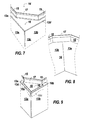
- Each side wall 13 is folded along an edge 13d horizontal to form a 13th narrow horizontal return (Figure 7). At 13e back connects a rectilinear edge 15 erected vertically.
- Terms “horizontal” and “vertical” are used here to simplify and understand each other by reference to the figures.
- the body 10 has a horizontal angle range 16 adjacent to a edge 17 erected substantially vertically.
- the beach 16 is substantially triangular and interconnects the 13th returns of the adjacent walls, while the edge 17 connects between them the erect edges 15 of the walls 13a, 13b, thus forming between these edges an oblique transition, for example at 45 °.
- the succession of edges 15 and 17 constitutes an octagonal contour which defines the opening 14 and whose upper edge forms a support for a seal (26, Figure 6) of the cover 20.
- the cover 20 is composed of a plate rectangular metal rectangular 22 and four corner pieces reported 30, these parts being of any suitable material.
- the plate 22 is extended around its periphery by folded edges 23 and, at all four angles, it has through openings 24 (Figure 5) cut in order to receive the corner pieces 30.
- the edges 23 In the corner region, the edges 23 have, on the side internal and at the opening 24, corner zones 23a (FIGS. 5 and 6) ensuring maintaining the corner piece 30; the zones 23a can for this purpose be provided of assembly forms 23b for example recessed.
- the corner piece 30 serves to cover the corner area of the edges 23.
- the piece 30 has an upper wall 31 which forms a support bracket 31a (FIG. 5) on a corresponding area 22a of the upper face of the plate 22.
- the corner piece 30 also has a side wall 32, of shape adapted to that of the edges 23.
- the wall 32 is presented as a dihedron with two faces 32a orthogonal to each other and at the top wall 31.
- the corner piece 30 has a wall 32 of left shape adapted to this curved shape.
- the faces 32a of the dihedron are provided with assembly forms 32b complementary forms 23b.
- the corner piece 30 also has a stud cylindrical 33 ( Figures 4 and 5) ensuring the nesting in the opening 24 and having a housing 34 for a screw 41 for fixing the cover 20 to the body 10 of the box.
- Fixing the corner piece 30 may alternatively be made by pinching the cover 20, by means of a suitable clevis.
- the pinch screed can be combined with assembly forms 32b.
- the screw 41 for fixing ( Figure 10) has a head 41 has housed in a portion 34a of the housing 34 and a rod 41b threaded or hook-shaped, guided in passage 34b.
- the screw 41 has an axis perpendicular to the plane of the plate 22 and is introduced along this axis into the corner piece 30.
- the corner piece 30 is fixed on the bearing surface 22a of the plate 22 and against the edges 23 by clipping, bonding, riveting or other similar method of attachment.
- corner pieces reported can easily be differentiated to vary the appearance of the lid, while allowing to add to the same metal plate 22 clamping elements - screws or quarter-turn elements - with various impressions, the studs 33 having a shape and a housing 34 adapted to these various elements of Tightening.
- the realization of the angle range and the transition edge corresponding can be done in different ways.
- the range 16 and the transition edge 17 do not mark any discontinuity with the 13th returns and the 15 edges, because the part the body located towards the lid is obtained from a piece by stamping.
- Part 10a is assembled in Part 10b (see line of seal figure 2) by any appropriate means.
- the angle piece 18 is for example welded on the one hand to 13th returns, especially along lines horizontal 18a parallel to the walls 13 (and to the horizontal edges 13d), and other share at the edges 15 along vertical lines 18b.
- the angle piece 18 may also have wings inserted under the 13th returns, these wings may be the case may be supported on the inner faces of the walls 13a, 13b.
- one of the walls offers a flap 19 which has just cut and extends its return 13e to constitute the angle range 16.
- the flap 19 can be folded to produce the oblique edge 17, or else this one can be provided as extending the upright edge 15 of the adjacent wall 13a.
- the application of the flap 19 is sealed for example by welding its side 19a at the end of the edge horizontal 13d, and from its front edge 19b (perpendicular to the side 19a) to the 13th return of the wall 13a.
- the edge 17, as a folded extension of the edge 15 of the wall 13a is welded on the one hand to the edge 15 of the wall 13b and on the other hand to the horizontal surface from the beach 16.
- the sealed fastening of the cover 20 to the body 10 is effected by means 40 of screw fasteners associated with the angle ranges 16 and does not alter the internal space of the box.
- the screws 41 associated with the cover 20 may be, as the case may be, quarter-turn fasteners or threaded screws.
- the axes of rotation of the screws are indicated in phantom in the figures.
- the arrangement adopted according to the invention makes it easy to change the screws 41, depending on the desired impression profile for their head: cruciform, double bar, square, triangle, etc.
- a through hole 16a is provided in the angle range 16 and a blind insert 42 is inserted into this orifice.
- the blind insert 42 has a blind sleeve 42c having a hole 42a for example threaded with which the screw cooperates, and a flange 42b for sealingly fastening, for example by welding, to the angle range 16.
- a stamping operation performed on the strips 16 creates a blind shape 44 similar to an insert 42, this shape being of shallow depth and threaded at 44a to receive the screw 41.
- no passage opening is provided in the angle range 16.
- a clamping piece 43 in particular a nut function, is placed on the track 16, this part having a generally flat shape, for example U-shaped overturned.
- the piece 43 has a horizontal core 43a provided with a threaded hole 43b, wings 43c and tabs 43d attachment to the upper face of the angle range 16.
- the height of the wings 43c is such that the screw 41 associated with the cover 20 can perform its clamping stroke.
Landscapes
- Engineering & Computer Science (AREA)
- Architecture (AREA)
- Civil Engineering (AREA)
- Structural Engineering (AREA)
- Microelectronics & Electronic Packaging (AREA)
- Casings For Electric Apparatus (AREA)
Abstract
Description
- le couvercle comprend des pièces de coin rapportées au-dessus de la plaque pour couvrir les ouvertures traversantes, en étant appliquées par un bandeau sur la face supérieure de la plaque,
- chaque pièce de coin comprend un logement adapté à une introduction de la vis de fixation respective selon son axe. L'ouverture traversante de la plaque mince peut être délimitée par des zones d'angle des bords rabattus qui se rejoignent.La pièce de coin peut présenter avantageusement une paroi latérale, soit en forme de dièdre, soit de forme incurvée, recouvrant les zones d'angle des bords rabattus du couvercle. La paroi latérale peut offrir vers l'intérieur des formes d'assemblage coopérant avec des formes complémentaires prévues sur les zones d'angle des bords rabattus et/ou offrir une chape d'assemblage par pincement sur le couvercle.La pièce de coin présente un logement adapté au type de vis de fixation, de préférence ménagé dans un plot tel que les zones d'angle des bords rabattus du couvercle sont insérées ou encastrées entre le plot et la paroi latérale.Un autre but de l'invention est de permettre de fixer de manière étanche le couvercle au corps d'une boíte pour organes électriques, sans altérer en pratique l'espace interne parallélépipédique du corps qui sert à loger les organes électriques, et ce à l'aide de moyens simples et peu coûteux.Cet autre but est atteint par le fait que,
- les extrémités des bords dressés situées aux coins du corps sont raccordées entre elles par des bords de transition, orientés de manière à ménager aux coins du corps des plages d'angle sensiblement triangulaires,
- sur le côté de la plage d'angle situé vers le couvercle est prévu un élément récepteur, disposé de façon étanche vis à vis de l'espace interne du corps, et coopérant, de façon également étanche vis à vis de l'espace interne et pratiquement sans réduire le volume utile de cet espace sous la plage d'angle, avec une vis de fixation du couvercle.
Dans un premier mode de réalisation (figure 11), un orifice de passage 16a est prévu dans la plage d'angle 16 et un insert borgne 42 est introduit dans cet orifice. L'insert borgne 42 présente une douille borgne 42c présentant un trou 42a par exemple taraudé avec lequel coopère la vis, et une collerette 42b permettant la fixation étanche, par exemple par soudage, à la plage d'angle 16.
Dans un deuxième mode de réalisation (figure 12), une opération d'emboutissage exécutée sur les plages 16 crée une forme borgne 44 similaire à un insert 42, cette forme étant de faible profondeur et taraudée en 44a pour recevoir la vis 41.
Dans un troisième mode de réalisation (figure 13), aucun orifice de passage n'est prévu dans la plage d'angle 16. Une pièce de serrage 43, notamment à fonction d'écrou, est placée sur la plage 16, cette pièce ayant une forme générale plate par exemple en U renversé. Plus précisément, la pièce 43 présente une âme horizontale 43a dotée d'un trou taraudé 43b, des ailes 43c et des pattes 43d de fixation à la face supérieure de la plage d'angle 16. La hauteur des ailes 43c est telle que la vis 41 associée au couvercle 20 puisse effectuer sa course de serrage.
| 10 | corps | 10a, 10b parties |
| 12 | fond | |
| 13 | parois latérales | 13a, 13b parois contiguës |
| 14 | ouverture | |
| 15 | bord dressé | |
| 16 | plage d'angle | 16a passage |
| 17 | bord de transition oblique | |
| 18 | pièce cornière | 18a, 18b lignes |
| 20 | couvercle | |
| 22 | plaque plane | 22a aire d'appui du coin rapporté |
| 23 | bord rabattu | 23a zones d'angle 23b formes d'assemblage |
| 24 | évidement d'angle | |
| 26 | joint d'étanchéité | |
| 30 | coin rapporté | |
| 31 | plaquette supérieure | 31a équerre d'appui |
| 32 | paroi latérale | 32a faces perpendiculaires 32b formes d'assemblage |
| 33 | plot d'emboítement | |
| 34 | logement de vis | 34a logement de la tête 34b passage de la tige |
| 40 | Dispositifs de fixation | |
| 41 | vis de fixation | 41 a tête de vis 41b tige filetée |
| 42 | insert borgne | 42a trou taraudé 42b collerette de fixation 42c tube |
| 43 | pièce d'écrou | 43a âme 43b trou taraudé 43c ailes 43d pattes de fixation |
| 44 | embouti borgne | 44a filetage |
Claims (17)
- Boíte métallique, notamment pour organes électriques, comprenant un corps (10) sensiblement parallélépipédique à fermer par un couvercle, porte ou organe analogue métallique (20) au moyen de vis (41) de fixation, placés aux coins, le corps (10) présentant quatre parois (13) latérales planes et une ouverture frontale, des logements (34) étant prévus pour les vis (41) de fixation aux angles du couvercle (20),
caractérisée par le fait quele couvercle (20) comprend une plaque mince (22) à bords rabattus (23), la plaque étant dotée aux angles d'ouvertures traversantes découpées (24) plus grandes que les logements des têtes des vis de fixation,le couvercle (20) comprend des pièces de coin (30) rapportées au-dessus de la plaque (22) pour couvrir les ouvertures traversantes, en étant appliquées par un bandeau (31) sur la face supérieure (22a) de la plaque,chaque pièce de coin (30) comprend un logement (34) adapté à une introduction de la vis de fixation respective (41) selon son axe. - Boíte selon la revendication 1, caractérisée par le fait que l'ouverture traversante (24) de la plaque mince (22) est délimitée par des zones d'angle (23a) des bords rabattus (23).
- Boíte selon la revendication 1, caractérisée par le fait que la pièce de coin (30) présente une paroi latérale (32) recouvrant les zones d'angle (23a) des bords rabattus (23) du couvercle (20).
- Boíte selon la revendication 3, caractérisée par le fait que la paroi latérale (32) offre vers l'intérieur des formes d'assemblage (32b) coopérant avec des formes complémentaires (23b) prévues sur les zones d'angle (23a) des bords rabattus (23).
- Boíte selon la revendication 3, caractérisée par le fait que la paroi latérale (32) forme un dièdre (31).
- Boíte selon la revendication 1, caractérisée par le fait que la pièce de coin (30) présente un logement (34) adapté au type de vis de fixation (41).
- Boíte selon la revendication 6, caractérisée par le fait que la pièce de coin (30) présente une paroi latérale (32) recouvrant les zones d'angle (23a) des bords rabattus (23) du couvercle (20) et que le logement (34) adapté au type de vis de fixation est ménagé dans un plot (33) tel que les zones d'angle (23a) des bords rabattus (23) du couvercle sont insérées ou encastrées entre le plot (33) et la paroi latérale (32).
- Boíte selon l'une des revendications 1 à 7, caractérisée par le fait que,l'ouverture frontale de son corps (10) est délimitée par un cadre continu formé par des retours (13e) de ses parois (13) latérales, chaque retour se prolongeant par un bord rectiligne (15) dressé de manière sensiblement parallèle à la paroi,les extrémités des bords dressés (15) situées aux coins du corps (10) sont raccordées entre elles par des bords de transition (17), orientés de manière à ménager aux coins du corps des plages d'angle (16) sensiblement triangulaires,sur le côté de la plage d'angle (16) situé vers le couvercle est prévu un élément récepteur (42,43,44), disposé de façon étanche vis à vis de l'espace interne du corps, et coopérant, de façon également étanche vis-à-vis de l'espace interne et pratiquement sans réduire le volume utile de cet espace sous la plage d'angle, avec la vis (41) de fixation du couvercle.
- Boíte selon la revendication 8, caractérisée par le fait que, en au moins un coin du corps, le bord de transition oblique (17) et la plage d'angle (16) associée viennent d'emboutissage avec le reste du corps.
- Boíte selon la revendication 8, caractérisée par le fait que, en au moins un coin du corps, le bord de transition oblique (17) et la plage d'angle (16) associée viennent de pliage à partir d'une paroi latérale (13b) du corps et sont soudés à la paroi adjacente (13a) et au retour et au bord dressé (15) de la paroi adjacente (13a).
- Boíte selon la revendication 8, caractérisée par le fait que, en au moins un coin du corps, le bord de transition oblique (17) et la plage d'angle associée (16) sont prévus sur une pièce cornière (18) de forme générale triangulaire, rapportée et fixée de manière étanche aux retours (13e) et bords dressés (15) des parois (13a,13b) formant le coin respectif.
- Boíte selon la revendication 11, caractérisée par le fait que la pièce cornière (18) a des ailes insérées sous les retours (13e) des parois latérales (13).
- Boíte selon la revendication 8, caractérisée par le fait que la plage d'angle (16) présente un passage traversant (16a) qui communique avec l'intérieur du corps, et l'élément récepteur de vis est un insert borgne (42) présentant une collerette (42b) fixée à la plage d'angle et un tube borgne (42c) pénétrant dans l'espace interne du corps sur une faible hauteur au-dessous de la plage, l'insert étant doté de formes internes (42a) pour le serrage de la vis de fixation (41) par filetage ou effet quart de tour.
- Boíte selon la revendication 8, caractérisée par le fait que la plage d'angle (16) est dépourvue de passage traversant, l'élément récepteur étant un trou borgne (44) embouti dans la plage d'angle (16) et doté d'un filetage interne (44a) de serrage pour la vis de fixation (41).
- Boíte selon la revendication 8, caractérisée par le fait que la plage d'angle (16) est dépourvue de passage traversant, et l'élément récepteur est une pièce (43) à fonction d'écrou, cette pièce d'écrou ayant une forme plate notamment en U renversé, dotée d'une âme (43a) à trou taraudé prévue pour coopérer avec la vis de fixation (41) et de pattes (43d) de fixation à la face externe de la plage d'angle (16).
- Boíte selon la revendication 8, caractérisée par le fait que la vis (41) de fixation du couvercle est du type quart de tour et l'élément récepteur (42,43) est adapté à bloquer cette vis en position de fermeture.
- Boíte selon la revendication 8, caractérisée par le fait que chaque retour se prolongeant par un bord rectiligne (15) dressé de manière sensiblement parallèle à la paroi constitue un contour continu d'application d'un joint (26) assurant l'étanchéité du couvercle (20).
Applications Claiming Priority (4)
| Application Number | Priority Date | Filing Date | Title |
|---|---|---|---|
| FR0401315A FR2866193B1 (fr) | 2004-02-10 | 2004-02-10 | Boite a coins etanches |
| FR0401315 | 2004-02-10 | ||
| FR0401317 | 2004-02-10 | ||
| FR0401317A FR2866194B1 (fr) | 2004-02-10 | 2004-02-10 | Couvercle de boite |
Publications (2)
| Publication Number | Publication Date |
|---|---|
| EP1564857A1 true EP1564857A1 (fr) | 2005-08-17 |
| EP1564857B1 EP1564857B1 (fr) | 2008-06-11 |
Family
ID=34702484
Family Applications (1)
| Application Number | Title | Priority Date | Filing Date |
|---|---|---|---|
| EP05100691A Expired - Lifetime EP1564857B1 (fr) | 2004-02-10 | 2005-02-01 | Boîte métallique notamment pour organes électriques |
Country Status (4)
| Country | Link |
|---|---|
| EP (1) | EP1564857B1 (fr) |
| AT (1) | ATE398352T1 (fr) |
| DE (1) | DE602005007394D1 (fr) |
| ES (1) | ES2304662T3 (fr) |
Cited By (3)
| Publication number | Priority date | Publication date | Assignee | Title |
|---|---|---|---|---|
| WO2015022730A1 (fr) * | 2013-08-13 | 2015-02-19 | 三菱電機株式会社 | Appareil électronique |
| WO2016190824A1 (fr) * | 2015-05-28 | 2016-12-01 | Em Elektri̇k Malzemeleri̇ Yükleni̇m Sanayi̇ Ti̇caret Anoni̇m Şi̇rketi̇ | Boîtiers de liaison étanches à l'eau et très résistants pour liaison transversale de systèmes de câbles à très haute tension |
| ITUA20162150A1 (it) * | 2016-03-31 | 2017-10-01 | Irinox S P A | Cassetta elettrica igienizzabile in lamiera di acciaio inox |
Families Citing this family (1)
| Publication number | Priority date | Publication date | Assignee | Title |
|---|---|---|---|---|
| DE102008060654B4 (de) | 2008-12-08 | 2018-03-22 | Hartmut Grunau | Endlagerbehäter und Verfahren zur Einbringung eines Gegenstands in denselben |
Citations (5)
| Publication number | Priority date | Publication date | Assignee | Title |
|---|---|---|---|---|
| GB2187228A (en) * | 1985-11-09 | 1987-09-03 | Appleby H & L Ltd | Hinge for a housing |
| DE4033109A1 (de) * | 1990-10-18 | 1992-04-23 | Rose Elektrotech Gmbh | Gehaeuse mit deckel-schnellverschluss und verfahren und formwerkzeug zur herstellung von verschlussteilen im gehaeuse |
| DE4037063A1 (de) * | 1990-11-22 | 1992-05-27 | Bopla Gehaeuse Systeme Gmbh | Gehaeuse, insbesondere zur aufnahme von elektrischen oder elektronischen bauelementen |
| US5361925A (en) * | 1991-08-19 | 1994-11-08 | Bernstein Compact Gehause Gmbh | Terminal box |
| DE29811893U1 (de) * | 1998-07-03 | 1998-10-01 | Rose-Elektrotechnik Gmbh & Co Kg Elektrotechnische Fabrik, 32457 Porta Westfalica | Gehäuse für elektrotechnische Bauteile |
-
2005
- 2005-02-01 EP EP05100691A patent/EP1564857B1/fr not_active Expired - Lifetime
- 2005-02-01 AT AT05100691T patent/ATE398352T1/de not_active IP Right Cessation
- 2005-02-01 ES ES05100691T patent/ES2304662T3/es not_active Expired - Lifetime
- 2005-02-01 DE DE602005007394T patent/DE602005007394D1/de not_active Expired - Lifetime
Patent Citations (5)
| Publication number | Priority date | Publication date | Assignee | Title |
|---|---|---|---|---|
| GB2187228A (en) * | 1985-11-09 | 1987-09-03 | Appleby H & L Ltd | Hinge for a housing |
| DE4033109A1 (de) * | 1990-10-18 | 1992-04-23 | Rose Elektrotech Gmbh | Gehaeuse mit deckel-schnellverschluss und verfahren und formwerkzeug zur herstellung von verschlussteilen im gehaeuse |
| DE4037063A1 (de) * | 1990-11-22 | 1992-05-27 | Bopla Gehaeuse Systeme Gmbh | Gehaeuse, insbesondere zur aufnahme von elektrischen oder elektronischen bauelementen |
| US5361925A (en) * | 1991-08-19 | 1994-11-08 | Bernstein Compact Gehause Gmbh | Terminal box |
| DE29811893U1 (de) * | 1998-07-03 | 1998-10-01 | Rose-Elektrotechnik Gmbh & Co Kg Elektrotechnische Fabrik, 32457 Porta Westfalica | Gehäuse für elektrotechnische Bauteile |
Cited By (4)
| Publication number | Priority date | Publication date | Assignee | Title |
|---|---|---|---|---|
| WO2015022730A1 (fr) * | 2013-08-13 | 2015-02-19 | 三菱電機株式会社 | Appareil électronique |
| JP5837264B2 (ja) * | 2013-08-13 | 2015-12-24 | 三菱電機株式会社 | 電子機器 |
| WO2016190824A1 (fr) * | 2015-05-28 | 2016-12-01 | Em Elektri̇k Malzemeleri̇ Yükleni̇m Sanayi̇ Ti̇caret Anoni̇m Şi̇rketi̇ | Boîtiers de liaison étanches à l'eau et très résistants pour liaison transversale de systèmes de câbles à très haute tension |
| ITUA20162150A1 (it) * | 2016-03-31 | 2017-10-01 | Irinox S P A | Cassetta elettrica igienizzabile in lamiera di acciaio inox |
Also Published As
| Publication number | Publication date |
|---|---|
| EP1564857B1 (fr) | 2008-06-11 |
| ES2304662T3 (es) | 2008-10-16 |
| DE602005007394D1 (de) | 2008-07-24 |
| ATE398352T1 (de) | 2008-07-15 |
Similar Documents
| Publication | Publication Date | Title |
|---|---|---|
| EP0935324B1 (fr) | Pilier d'angle pour armoire destinée à loger de l'appareillage électrique et armoire équipée d'un tel pilier | |
| EP1564857B1 (fr) | Boîte métallique notamment pour organes électriques | |
| FR2726730A1 (fr) | Armoire de distribution comportant un chassis-cadre, des elements de paroi et au moins une porte | |
| FR2866194A1 (fr) | Couvercle de boite | |
| FR2782535A1 (fr) | Dispositif de montage de commande d'ouverture de porte de vehicule | |
| EP1601074B9 (fr) | Armoire électrique à profilés d'ossature | |
| FR2781992A1 (fr) | Sac, rabat pour sac et son procede de montage | |
| FR2866193A1 (fr) | Boite a coins etanches | |
| FR2938286A1 (fr) | Gond reglable en position | |
| FR2639411A1 (fr) | Dispositif d'assemblage de deux elements et vis d'assemblage specialement concue pour ledit dispositif | |
| EP2120651B1 (fr) | Boîte aux lettres, livrable en kit | |
| FR2810298A1 (fr) | Emballage octogonal | |
| FR2780208A1 (fr) | Coffret a ouverture et equipe d'une piece de liaison mecanique pour la fixation de son dispositif d'obturation | |
| EP0895328B1 (fr) | Boite industrielle pour éléments électriques | |
| FR2952958A1 (fr) | Dispositif de maintien d'un organe flexible de transmission | |
| FR2777733A1 (fr) | Armoire electrique dont les montants du cadre sont realises par repliage de ses parois en formant un logement interieur | |
| FR2866630A1 (fr) | Emballage du genre boite en carton ou matiere similaire | |
| EP3758171B1 (fr) | Dispositif d'assemblage et armature d'armoire électrique comprenant un tel dispositif | |
| FR3027940A1 (fr) | Ouvrage de construction et ensemble comprenant un tel ouvrage de construction et menuiserie | |
| EP0665524A1 (fr) | Objet tel qu'une vitrine comprenant un cadre polygonal forme de profiles | |
| EP1149545B1 (fr) | Dispositif de fixation murale pour coffret | |
| EP2201861A1 (fr) | Meuble | |
| EP0869245B1 (fr) | Ferrure pour ouvrant coulissant pour porte, fenêtre ou analogue | |
| FR2742468A1 (fr) | Plaque d'engrenement de targette pour des fermetures de fenetres et de portes | |
| FR2886610A1 (fr) | Vehicule automobile a porte coulissante renforcee |
Legal Events
| Date | Code | Title | Description |
|---|---|---|---|
| PUAI | Public reference made under article 153(3) epc to a published international application that has entered the european phase |
Free format text: ORIGINAL CODE: 0009012 |
|
| AK | Designated contracting states |
Kind code of ref document: A1 Designated state(s): AT BE BG CH CY CZ DE DK EE ES FI FR GB GR HU IE IS IT LI LT LU MC NL PL PT RO SE SI SK TR |
|
| AX | Request for extension of the european patent |
Extension state: AL BA HR LV MK YU |
|
| 17P | Request for examination filed |
Effective date: 20050926 |
|
| AKX | Designation fees paid |
Designated state(s): AT BE BG CH CY CZ DE DK EE ES FI FR GB GR HU IE IS IT LI LT LU MC NL PL PT RO SE SI SK TR |
|
| GRAC | Information related to communication of intention to grant a patent modified |
Free format text: ORIGINAL CODE: EPIDOSCIGR1 |
|
| GRAP | Despatch of communication of intention to grant a patent |
Free format text: ORIGINAL CODE: EPIDOSNIGR1 |
|
| GRAS | Grant fee paid |
Free format text: ORIGINAL CODE: EPIDOSNIGR3 |
|
| GRAA | (expected) grant |
Free format text: ORIGINAL CODE: 0009210 |
|
| AK | Designated contracting states |
Kind code of ref document: B1 Designated state(s): AT BE BG CH CY CZ DE DK EE ES FI FR GB GR HU IE IS IT LI LT LU MC NL PL PT RO SE SI SK TR |
|
| REG | Reference to a national code |
Ref country code: GB Ref legal event code: FG4D Free format text: NOT ENGLISH |
|
| REG | Reference to a national code |
Ref country code: CH Ref legal event code: EP |
|
| REF | Corresponds to: |
Ref document number: 602005007394 Country of ref document: DE Date of ref document: 20080724 Kind code of ref document: P |
|
| REG | Reference to a national code |
Ref country code: IE Ref legal event code: FG4D Free format text: LANGUAGE OF EP DOCUMENT: FRENCH |
|
| REG | Reference to a national code |
Ref country code: SE Ref legal event code: TRGR |
|
| REG | Reference to a national code |
Ref country code: ES Ref legal event code: FG2A Ref document number: 2304662 Country of ref document: ES Kind code of ref document: T3 |
|
| PG25 | Lapsed in a contracting state [announced via postgrant information from national office to epo] |
Ref country code: FI Free format text: LAPSE BECAUSE OF FAILURE TO SUBMIT A TRANSLATION OF THE DESCRIPTION OR TO PAY THE FEE WITHIN THE PRESCRIBED TIME-LIMIT Effective date: 20080611 Ref country code: SI Free format text: LAPSE BECAUSE OF FAILURE TO SUBMIT A TRANSLATION OF THE DESCRIPTION OR TO PAY THE FEE WITHIN THE PRESCRIBED TIME-LIMIT Effective date: 20080611 |
|
| PG25 | Lapsed in a contracting state [announced via postgrant information from national office to epo] |
Ref country code: AT Free format text: LAPSE BECAUSE OF FAILURE TO SUBMIT A TRANSLATION OF THE DESCRIPTION OR TO PAY THE FEE WITHIN THE PRESCRIBED TIME-LIMIT Effective date: 20080611 Ref country code: NL Free format text: LAPSE BECAUSE OF FAILURE TO SUBMIT A TRANSLATION OF THE DESCRIPTION OR TO PAY THE FEE WITHIN THE PRESCRIBED TIME-LIMIT Effective date: 20080611 Ref country code: PL Free format text: LAPSE BECAUSE OF FAILURE TO SUBMIT A TRANSLATION OF THE DESCRIPTION OR TO PAY THE FEE WITHIN THE PRESCRIBED TIME-LIMIT Effective date: 20080611 |
|
| NLV1 | Nl: lapsed or annulled due to failure to fulfill the requirements of art. 29p and 29m of the patents act | ||
| PG25 | Lapsed in a contracting state [announced via postgrant information from national office to epo] |
Ref country code: CZ Free format text: LAPSE BECAUSE OF FAILURE TO SUBMIT A TRANSLATION OF THE DESCRIPTION OR TO PAY THE FEE WITHIN THE PRESCRIBED TIME-LIMIT Effective date: 20080611 Ref country code: LT Free format text: LAPSE BECAUSE OF FAILURE TO SUBMIT A TRANSLATION OF THE DESCRIPTION OR TO PAY THE FEE WITHIN THE PRESCRIBED TIME-LIMIT Effective date: 20080611 Ref country code: IS Free format text: LAPSE BECAUSE OF FAILURE TO SUBMIT A TRANSLATION OF THE DESCRIPTION OR TO PAY THE FEE WITHIN THE PRESCRIBED TIME-LIMIT Effective date: 20081011 |
|
| REG | Reference to a national code |
Ref country code: IE Ref legal event code: FD4D |
|
| PG25 | Lapsed in a contracting state [announced via postgrant information from national office to epo] |
Ref country code: RO Free format text: LAPSE BECAUSE OF FAILURE TO SUBMIT A TRANSLATION OF THE DESCRIPTION OR TO PAY THE FEE WITHIN THE PRESCRIBED TIME-LIMIT Effective date: 20080611 Ref country code: PT Free format text: LAPSE BECAUSE OF FAILURE TO SUBMIT A TRANSLATION OF THE DESCRIPTION OR TO PAY THE FEE WITHIN THE PRESCRIBED TIME-LIMIT Effective date: 20081111 Ref country code: SK Free format text: LAPSE BECAUSE OF FAILURE TO SUBMIT A TRANSLATION OF THE DESCRIPTION OR TO PAY THE FEE WITHIN THE PRESCRIBED TIME-LIMIT Effective date: 20080611 |
|
| PLBE | No opposition filed within time limit |
Free format text: ORIGINAL CODE: 0009261 |
|
| STAA | Information on the status of an ep patent application or granted ep patent |
Free format text: STATUS: NO OPPOSITION FILED WITHIN TIME LIMIT |
|
| PG25 | Lapsed in a contracting state [announced via postgrant information from national office to epo] |
Ref country code: BG Free format text: LAPSE BECAUSE OF FAILURE TO SUBMIT A TRANSLATION OF THE DESCRIPTION OR TO PAY THE FEE WITHIN THE PRESCRIBED TIME-LIMIT Effective date: 20080911 Ref country code: IE Free format text: LAPSE BECAUSE OF FAILURE TO SUBMIT A TRANSLATION OF THE DESCRIPTION OR TO PAY THE FEE WITHIN THE PRESCRIBED TIME-LIMIT Effective date: 20080611 Ref country code: EE Free format text: LAPSE BECAUSE OF FAILURE TO SUBMIT A TRANSLATION OF THE DESCRIPTION OR TO PAY THE FEE WITHIN THE PRESCRIBED TIME-LIMIT Effective date: 20080611 Ref country code: DK Free format text: LAPSE BECAUSE OF FAILURE TO SUBMIT A TRANSLATION OF THE DESCRIPTION OR TO PAY THE FEE WITHIN THE PRESCRIBED TIME-LIMIT Effective date: 20080611 |
|
| 26N | No opposition filed |
Effective date: 20090312 |
|
| BERE | Be: lapsed |
Owner name: SCHNEIDER ELECTRIC INDUSTRIES SAS Effective date: 20090228 |
|
| PG25 | Lapsed in a contracting state [announced via postgrant information from national office to epo] |
Ref country code: MC Free format text: LAPSE BECAUSE OF NON-PAYMENT OF DUE FEES Effective date: 20090228 |
|
| REG | Reference to a national code |
Ref country code: CH Ref legal event code: PL |
|
| PG25 | Lapsed in a contracting state [announced via postgrant information from national office to epo] |
Ref country code: CH Free format text: LAPSE BECAUSE OF NON-PAYMENT OF DUE FEES Effective date: 20090228 Ref country code: LI Free format text: LAPSE BECAUSE OF NON-PAYMENT OF DUE FEES Effective date: 20090228 |
|
| PG25 | Lapsed in a contracting state [announced via postgrant information from national office to epo] |
Ref country code: BE Free format text: LAPSE BECAUSE OF NON-PAYMENT OF DUE FEES Effective date: 20090228 |
|
| PG25 | Lapsed in a contracting state [announced via postgrant information from national office to epo] |
Ref country code: GR Free format text: LAPSE BECAUSE OF FAILURE TO SUBMIT A TRANSLATION OF THE DESCRIPTION OR TO PAY THE FEE WITHIN THE PRESCRIBED TIME-LIMIT Effective date: 20080912 |
|
| PG25 | Lapsed in a contracting state [announced via postgrant information from national office to epo] |
Ref country code: LU Free format text: LAPSE BECAUSE OF NON-PAYMENT OF DUE FEES Effective date: 20090201 |
|
| PG25 | Lapsed in a contracting state [announced via postgrant information from national office to epo] |
Ref country code: HU Free format text: LAPSE BECAUSE OF FAILURE TO SUBMIT A TRANSLATION OF THE DESCRIPTION OR TO PAY THE FEE WITHIN THE PRESCRIBED TIME-LIMIT Effective date: 20081212 |
|
| PG25 | Lapsed in a contracting state [announced via postgrant information from national office to epo] |
Ref country code: TR Free format text: LAPSE BECAUSE OF FAILURE TO SUBMIT A TRANSLATION OF THE DESCRIPTION OR TO PAY THE FEE WITHIN THE PRESCRIBED TIME-LIMIT Effective date: 20080611 |
|
| PG25 | Lapsed in a contracting state [announced via postgrant information from national office to epo] |
Ref country code: CY Free format text: LAPSE BECAUSE OF FAILURE TO SUBMIT A TRANSLATION OF THE DESCRIPTION OR TO PAY THE FEE WITHIN THE PRESCRIBED TIME-LIMIT Effective date: 20080611 |
|
| REG | Reference to a national code |
Ref country code: FR Ref legal event code: PLFP Year of fee payment: 12 |
|
| REG | Reference to a national code |
Ref country code: FR Ref legal event code: PLFP Year of fee payment: 13 |
|
| REG | Reference to a national code |
Ref country code: FR Ref legal event code: PLFP Year of fee payment: 14 |
|
| PGFP | Annual fee paid to national office [announced via postgrant information from national office to epo] |
Ref country code: ES Payment date: 20240307 Year of fee payment: 20 |
|
| PGFP | Annual fee paid to national office [announced via postgrant information from national office to epo] |
Ref country code: DE Payment date: 20240228 Year of fee payment: 20 Ref country code: GB Payment date: 20240220 Year of fee payment: 20 |
|
| PGFP | Annual fee paid to national office [announced via postgrant information from national office to epo] |
Ref country code: SE Payment date: 20240226 Year of fee payment: 20 Ref country code: IT Payment date: 20240222 Year of fee payment: 20 Ref country code: FR Payment date: 20240226 Year of fee payment: 20 |
|
| REG | Reference to a national code |
Ref country code: DE Ref legal event code: R071 Ref document number: 602005007394 Country of ref document: DE |
|
| REG | Reference to a national code |
Ref country code: GB Ref legal event code: PE20 Expiry date: 20250131 Ref country code: ES Ref legal event code: FD2A Effective date: 20250226 |
|
| REG | Reference to a national code |
Ref country code: SE Ref legal event code: EUG |
|
| PG25 | Lapsed in a contracting state [announced via postgrant information from national office to epo] |
Ref country code: ES Free format text: LAPSE BECAUSE OF EXPIRATION OF PROTECTION Effective date: 20250202 |
|
| PG25 | Lapsed in a contracting state [announced via postgrant information from national office to epo] |
Ref country code: GB Free format text: LAPSE BECAUSE OF EXPIRATION OF PROTECTION Effective date: 20250131 |