EP1564521A1 - Geschoss mit vom Geschoss-Rumpf wegklappbaren Flügeln - Google Patents
Geschoss mit vom Geschoss-Rumpf wegklappbaren Flügeln Download PDFInfo
- Publication number
- EP1564521A1 EP1564521A1 EP05002218A EP05002218A EP1564521A1 EP 1564521 A1 EP1564521 A1 EP 1564521A1 EP 05002218 A EP05002218 A EP 05002218A EP 05002218 A EP05002218 A EP 05002218A EP 1564521 A1 EP1564521 A1 EP 1564521A1
- Authority
- EP
- European Patent Office
- Prior art keywords
- projectile
- covering
- tensioning cable
- spar
- front spar
- Prior art date
- Legal status (The legal status is an assumption and is not a legal conclusion. Google has not performed a legal analysis and makes no representation as to the accuracy of the status listed.)
- Granted
Links
- 239000004744 fabric Substances 0.000 claims description 12
- 230000007423 decrease Effects 0.000 claims description 5
- 238000005452 bending Methods 0.000 abstract description 7
- 210000004262 dental pulp cavity Anatomy 0.000 description 3
- 230000033001 locomotion Effects 0.000 description 2
- 238000011161 development Methods 0.000 description 1
- 230000018109 developmental process Effects 0.000 description 1
- 238000004519 manufacturing process Methods 0.000 description 1
- 238000012856 packing Methods 0.000 description 1
- 230000008092 positive effect Effects 0.000 description 1
Images

Classifications
-
- F—MECHANICAL ENGINEERING; LIGHTING; HEATING; WEAPONS; BLASTING
- F42—AMMUNITION; BLASTING
- F42B—EXPLOSIVE CHARGES, e.g. FOR BLASTING, FIREWORKS, AMMUNITION
- F42B10/00—Means for influencing, e.g. improving, the aerodynamic properties of projectiles or missiles; Arrangements on projectiles or missiles for stabilising, steering, range-reducing, range-increasing or fall-retarding
- F42B10/02—Stabilising arrangements
- F42B10/14—Stabilising arrangements using fins spread or deployed after launch, e.g. after leaving the barrel
- F42B10/146—Fabric fins, i.e. fins comprising at least one spar and a fin cover made of flexible sheet material
Definitions
- the invention relates to a projectile with fold away from the projectile fuselage Wings according to the preamble of claim 1.
- Such a projectile is known from DE 33 40 501 C2.
- this known projectile has the aerodynamically profiled front spar of respective wing a relatively large width. Tread depth on, so in the Projectile hull a correspondingly large receiving space for the respective Wing must be provided.
- the rear spar can be at this known Projectile designed as an aerodynamically profiled rigid body or of be formed a tension cable.
- the guy rope is with his first End portion connected to the outer end of the front spar such that on the front spar in the folded away from the projectile fuselage state of Wing flexing is effective.
- the front spar is the front spar with a correspondingly large tread depth dimensioned.
- DE 34 03 573 A1 which is an additional patent application for The above-mentioned DE 33 40 501 C2, is a projectile of the Projectile fuselage known as foldable wings, with the respective wing has a front spar with a relatively large tread depth and the rear spar may be formed by a rigid body or a tension cable. Also in this known projectile, the first end portion of the Schuholms with the outer end of the front spar connected in such a way that from the projectile fuselage folded state of the wing on the front spar one Bending stress becomes effective when the rear spar of a tensioning cable is formed.
- DE 35 23 769 A1 discloses a submunition missile with adjustable sliding wings, wherein the respective sliding wing a front spar relatively large tread depth and a rear spar, the one of a rigid Body or can be formed by a tension cable. Also with this known missile is the rear spar forming tension cable with his first end portion connected to the outer end of the front spar such in the unfolded state of the wing of the front spar on bend is claimed.
- a wing housing for a missile with a Self-righting wing assembly with elements known, each one Chamber, which has a self-righting wing in the folded state picks up, and form an opening through which the wing is erected extends, with a ejectable lid, the detachable above the opening is appropriate.
- the wing housing has a base plate, which as Storage element for struts of the wing and for clamping a Cloth covering of the wing on the wing housing is used.
- the cloth covering the wing surrounds the struts and has an apron, which between the Base plate and a circumferential clamping strip of the wing housing is clamped.
- the invention is based on the object, a projectile of the beginning mentioned type with small-packing wings to create the high Have lift coefficients.
- the tensioning cable with its first end portion with the outer end of the front spar in the direction of the front spar, with this at least approximately aligned, connected, and the tensioning cable with his second end portion to a provided in the projectile fuselage Clamping device is connected, so that the tensioning cable and the Covered in the unfolded state of the wing between the unfolded fixed front spar and formed by the tensioned tension rope Rear spar are permanently stretched, the front spar is unfolded Condition not or only negligible on bending but only on Pressure claimed, which is why the front spar with a relatively small tread depth may be formed, resulting in the advantage that the respective wing is small packed, i. in the folded state, only a small receptacle or storage space needed.
- the tensioning device for the tensioning cable can be formed by a spring element be. Likewise, it is possible that the tensioning device for the tensioning cable a pyrotechnic element or a piston-cylinder unit.
- the tread depth of the front spar decrease from its inner end to its outer end. This decrease can be continuous, but it is advantageous if the tread depth of Vorderholms from its inner end to its outer end in sections Gradually decreases, because such a trained front spar easy is feasible.
- the covering a concave Has curved rear edge, in the unfolded state of the wing is stretched by the permanently tensioned tension rope, so that a Fluttering movement of the covering is prevented.
- the rear edge of the Covering is concavely curved in such a way that this against the concave curved rear edge forced tensioned tension cable with its first End portion with the outer end of the front spar at least approximately is aligned to a bending stress of the front spar of the to avoid unfolded wing.
- the fabric is double-layered, wherein the Front spar and the tensioning cable between the two layers of the clothing are provided.
- the covering of the respective wing with its root edge attached to the projectile fuselage it is preferred if the Root edge of the fabric is slightly concave, in order from the Projectile fuselage folded flight condition of the wing the stringing to tighten all sides in such a way that the desired high lift coefficient is achieved becomes.
- root edge of the two-ply fabric each with a Umschlagrand is formed by the two root edge channels for Root rods are formed, extending along the projectile trunk extend.
- the projectile according to the invention has the advantages that the Volume requirement for the respective wing in the folded state is low, that the bending stress of the front spar of the respective, from the projectile hull folded wing is very small or negligible small that the wing covering over all its edges, i. through the front edge the front spar, over the rear edge by the concave rear spar forming tension rope and along the root edge by the slight concave trained root edge of the clothing is tensionable, that of the Projectile fuselage folded wings have a high buoyancy coefficient, and that the respective wing consists of a few individual parts, so that the Production costs are correspondingly low.
- FIG. 1 shows a section of a projectile 10 in a sectional view with folding away from the projectile fuselage 12 wings 14, of which in FIG 1 is shown only one folded away from the projectile fuselage 12 state.
- the wing 14 has a front rail 16, the inner end 18 to a Axis 20 from a space-saving folded position in the in Figure 1 drawn unfolded flight position is adjustable. In the unfolded Flight position is the front spar 16 by means of a suitable device from Projectile fuselage 12 fixed away.
- the rear spar 22 of the wing 14 is formed by a tensioning cable 24, which with its first end portion 26 with the outer end 28 of the front spar 16 and that with its second end portion 30 with a in the projectile fuselage 12th provided clamping device 32 is connected.
- the tensioning cable 24 is with its first end portion 26 with the outer end 28 of the front spar 16 in Direction of the front spar 16 - with this at least approximately aligned - connected so that the tensioned by means of the clamping device 32 tensioning cable 24 in the unfolded state of the wing 14 in the front spar 16 no or only a negligible bending load but only a compressive load initiates. Therefore, it is possible, the aerodynamically profiled front spar 16 relative narrow, i. with a relatively small tread depth, form.
- the profile depth of the Vorderholmes 16 increases from the inner end 18 to the outer end 28 graduated in sections. These sections are identified by the reference numbers 34, Designated 36 and 38.
- the Covering 40 is formed in two layers.
- the two layers 42 and 44 are along the leading edge 46 of the fabric 40 with each centrein Published.
- the two layers 42 and 44 of the fabric 40 have a concavely curved trailing edge 48.
- Parallel to the rear edge 48 runs in Immediate neighborhood of the same a hem seam 50. At this seam seam 50 comes the tension cable 24 closely to the system when the wing 15 in the in Figure 1 drawn unfolded flight position is.
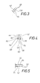
- Each of the two layers 42 and 44 of the fabric 40 has a the Projectile fuselage 12 facing root edge 52 on. As shown in FIG. 4 can be seen, the root edge 52 of each layer 42, 44 a Umzzirand 54 on. The Umschlagr selected 54 of the two layers 42, 44 of the fabric 40th are turned away from each other. Each envelope flap 54 is associated with the one Layer 42 and 44 connected by a hem seam 56, so that two Root canals 58 for bullet-proof root bars 60 (see also FIG. 1) result. The root bars 60 extend along the projectile trunk 12 of the projectile 10.
- the root canals 58 are back completed by a closing seam 62, which extends along the two Envelope 54 extends and the hem seam 50 crosses.
Landscapes
- Physics & Mathematics (AREA)
- Fluid Mechanics (AREA)
- Engineering & Computer Science (AREA)
- General Engineering & Computer Science (AREA)
- Aiming, Guidance, Guns With A Light Source, Armor, Camouflage, And Targets (AREA)
Abstract
Description
- Figur 1
- abschnittweise längsgeschnitten ein Ausführungsbeispiel des Geschosses mit vom Geschoss-Rumpf weggeklapptem Flügel,
- Figur 2
- die Bespannung des Flügels gemäß Figur 1 im aufgespannten Zustand,
- Figur 3
- einen Schnitt entlang der Schnittlinie A-A in Figur 2,
- Figur 4
- einen Schnitt entlang der Schnittlinie B-B in Figur 2, und
- Figur 5
- einen Schnitt entlang der Schnittlinie C-C in Figur 2.
- 10
- Geschoss
- 12
- Geschoss-Rumpf (von 10)
- 14
- Flügel (an 12)
- 16
- Vorderholm (von 14)
- 18
- Innenende (von 16)
- 20
- Achse (an 18)
- 22
- Hinterholm (von 14)
- 24
- Spannseil (für 22)
- 26
- erster Endabschnitt (von 24)
- 28
- Außenende (von 16)
- 30
- zweiter Endabschnitt (von 24)
- 32
- Spanneinrichtung (für 24 an 30)
- 34
- Abschnitt (von 16)
- 36
- Abschnitt (von 16)
- 38
- Abschnitt (von 16)
- 40
- Bespannung (von 14)
- 42
- Lage (von 40)
- 44
- Lager (von 40)
- 46
- Vorderkante (von 40)
- 48
- Hinterrand (von 42, 44)
- 50
- Saumnaht (bei 48 zwischen 42 und 44)
- 52
- Wurzelrand (von 40 bzw. 42 und 44)
- 54
- Umschlagrand (von 52)
- 56
- Saumnaht (zwischen 42, 44 und 54)
- 58
- Wurzelkanäle (bei 52 für 60)
- 60
- Wurzelstangen (von 12)
- 62
- Abschlussnaht (von 58)
Claims (11)
- Geschoss mit vom Geschoss-Rumpf (12) wegklappbaren Flügeln (14), die jeweils einen Vorderholm (16), ein den Hinterholm (22) bildendes Spannseil (24), und eine zwischen dem Vorder- und dem Hinterholm (16 und 22) vorgesehene Bespannung (40) aufweisen, wobei der Vorderholm (16) aerodynamisch profiliert und mit seinem Innenende (18) am Geschoss-Rumpf (12) angelenkt ist, und das den Hinterholm (22) bildende Spannseil (24) mit seinem ersten Endabschnitt (26) mit dem Außenende (28) des Vorderholms (16) und mit seinem zweiten Endabschnitt (30) mit dem Geschoss-Rumpf (12) verbunden ist,
dadurch gekennzeichnet, dass das Spannseil (24) mit seinem ersten Endabschnitt (26) mit dem Außenende (28) des Vorderholms (16) in Richtung des Vorderholms (16), mit diesem mindestens annähernd fluchtend, verbunden ist, und dass das Spannseil (24) mit seinem zweiten Endabschnitt (30) an eine im Geschoss-Rumpf (12) vorgesehene Spanneinrichtung (32) angeschlossen ist, so dass das Spannseil (24) und die Bespannung (40) im aufgeklappten Zustand des Flügels (14) zwischen dem aufgeklappt fixierten Vorderholm (16) und dem vom gespannten Spannseil (24) gebildeten Hinterholm (22) permanent gespannt sind. - Geschoss nach Anspruch 1,
dadurch gekennzeichnet, dass die Spanneinrichtung (32) für das Spannseil (24) von einem Federelement gebildet ist. - Geschoss nach Anspruch 1,
dadurch gekennzeichnet, dass die Spanneinrichtung (32) für das Spannseil (24) ein pyrotechnisches Element aufweist. - Geschoss nach Anspruch 1,
dadurch gekennzeichnet, dass die Spanneinrichtung (32) für das Spannseil (24) eine Kolben-Zylinder-Einheit aufweist. - Geschoss nach Anspruch 1,
dadurch gekennzeichnet, dass die Profiltiefe des Vorderholms (16) von seinem Innenende (18) zu seinem Außenende (28) hin abnimmt. - Geschoss nach Anspruch 5,
dadurch gekennzeichnet, dass die Profiltiefe des Vorderholms (16) von seinem Innenende (18) zu seinem Außenende (28) hin abschnittweise (Abschnitte 34, 36, 38) abgestuft abnimmt. - Geschoss nach Anspruch 1,
dadurch gekennzeichnet, dass die Bespannung (40) einen konkav gekrümmten Hinterrand (48) aufweist, gegen den im aufgeklappten Zustand des Flügels (14) das permanent gespannte Spannseil (24) gezwängt ist. - Geschoss nach einem der Ansprüche 1 bis 7,
dadurch gekennzeichnet, dass die Bespannung (40) zwei Lagen (42, 44) aufweist, wobei der Vorderholm (16) und das Spannseil (24) zwischen den beiden Lagen (42, 44) der Bespannung (40) vorgesehen sind. - Geschoss nach einem der Ansprüche 1 bis 8,
dadurch gekennzeichnet, dass die Bespannung (40) mit ihrem Wurzelrand (52) am Geschoss-Rumpf (12) angebracht ist. - Geschoss nach Anspruch 9,
dadurch gekennzeichnet, dass der Wurzelrand (52) der Bespannung (40) geringfügig konkav ausgebildet ist. - Geschoss nach einem der Ansprüche 8 bis 10,
dadurch gekennzeichnet, dass der Wurzelrand (52) der zweilagigen Bespannung (40) jeweils mit einem Umschlagrand (54) ausgebildet ist, durch den zwei Wurzelrandkanäle (58) für Wurzelstangen (60) gebildet sind, die sich entlang des Geschoss-Rumpfes (12) erstrecken.
Applications Claiming Priority (2)
| Application Number | Priority Date | Filing Date | Title |
|---|---|---|---|
| DE200410007311 DE102004007311A1 (de) | 2004-02-14 | 2004-02-14 | Geschoss mit vom Geschoss-Rumpf wegklappbaren Flügeln |
| DE102004007311 | 2004-02-14 |
Publications (2)
| Publication Number | Publication Date |
|---|---|
| EP1564521A1 true EP1564521A1 (de) | 2005-08-17 |
| EP1564521B1 EP1564521B1 (de) | 2006-09-27 |
Family
ID=34684059
Family Applications (1)
| Application Number | Title | Priority Date | Filing Date |
|---|---|---|---|
| EP20050002218 Expired - Lifetime EP1564521B1 (de) | 2004-02-14 | 2005-02-03 | Geschoss mit vom Geschoss-Rumpf wegklappbaren Flügeln |
Country Status (2)
| Country | Link |
|---|---|
| EP (1) | EP1564521B1 (de) |
| DE (2) | DE102004007311A1 (de) |
Citations (5)
| Publication number | Priority date | Publication date | Assignee | Title |
|---|---|---|---|---|
| DE3234269C2 (de) | 1982-02-10 | 1985-05-09 | General Dynamics Corp., Pomona, Calif. | Flügelgehäuse für einen Flugkörper mit einer selbstaufrichtenden Flügelanordnung |
| DE3340501A1 (de) * | 1983-11-09 | 1985-05-15 | Diehl GmbH & Co, 8500 Nürnberg | Geschoss mit herausklappbaren fluegeln |
| DE3403573A1 (de) | 1983-11-09 | 1985-08-08 | Diehl GmbH & Co, 8500 Nürnberg | Geschoss mit herausklappbaren fluegeln |
| DE3523769A1 (de) | 1985-07-03 | 1987-01-08 | Diehl Gmbh & Co | Submunitions-flugkoerper mit ausstellbaren gleitfluegeln |
| FR2613474A1 (fr) * | 1987-04-03 | 1988-10-07 | Thomson Brandt Armements | Element de voilure gonflable, notamment pour un engin volant |
Family Cites Families (6)
| Publication number | Priority date | Publication date | Assignee | Title |
|---|---|---|---|---|
| US3990656A (en) * | 1974-09-30 | 1976-11-09 | The United States Of America As Represented By The Secretary Of The Army | Pop-up fin |
| DE3417082A1 (de) * | 1984-05-09 | 1985-11-14 | Diehl GmbH & Co, 8500 Nürnberg | Klapp-fluegel, insbesondere fuer ein geschoss |
| GB8815060D0 (en) * | 1988-06-24 | 1988-11-16 | British Aerospace | Fin assembly for projectile |
| DE3838738A1 (de) * | 1988-11-15 | 1990-05-23 | Diehl Gmbh & Co | Projektil mit ausklappbaren fluegeln |
| DE3838735C2 (de) * | 1988-11-15 | 1997-12-18 | Diehl Gmbh & Co | Klapp-Flügel, insbes. für ein Geschoss |
| DE3838895A1 (de) * | 1988-11-17 | 1990-07-05 | Diehl Gmbh & Co | Fluegel fuer ein geschoss |
-
2004
- 2004-02-14 DE DE200410007311 patent/DE102004007311A1/de not_active Withdrawn
-
2005
- 2005-02-03 EP EP20050002218 patent/EP1564521B1/de not_active Expired - Lifetime
- 2005-02-03 DE DE200550000114 patent/DE502005000114D1/de not_active Expired - Lifetime
Patent Citations (6)
| Publication number | Priority date | Publication date | Assignee | Title |
|---|---|---|---|---|
| DE3234269C2 (de) | 1982-02-10 | 1985-05-09 | General Dynamics Corp., Pomona, Calif. | Flügelgehäuse für einen Flugkörper mit einer selbstaufrichtenden Flügelanordnung |
| DE3340501A1 (de) * | 1983-11-09 | 1985-05-15 | Diehl GmbH & Co, 8500 Nürnberg | Geschoss mit herausklappbaren fluegeln |
| DE3403573A1 (de) | 1983-11-09 | 1985-08-08 | Diehl GmbH & Co, 8500 Nürnberg | Geschoss mit herausklappbaren fluegeln |
| DE3340501C2 (de) | 1983-11-09 | 1986-12-04 | Diehl GmbH & Co, 8500 Nürnberg | Geschoß mit herausklappbaren Flügeln |
| DE3523769A1 (de) | 1985-07-03 | 1987-01-08 | Diehl Gmbh & Co | Submunitions-flugkoerper mit ausstellbaren gleitfluegeln |
| FR2613474A1 (fr) * | 1987-04-03 | 1988-10-07 | Thomson Brandt Armements | Element de voilure gonflable, notamment pour un engin volant |
Also Published As
| Publication number | Publication date |
|---|---|
| DE502005000114D1 (de) | 2006-11-09 |
| DE102004007311A1 (de) | 2005-09-01 |
| EP1564521B1 (de) | 2006-09-27 |
Similar Documents
| Publication | Publication Date | Title |
|---|---|---|
| DE2737597C2 (de) | ||
| DE60110381T2 (de) | Durch stauluft aufgeblasener flügel | |
| DE10063581B4 (de) | Luftleitvorrichtung für ein Faltverdeck eines Kraftfahrzeugs | |
| DE3417082C2 (de) | ||
| DE102010032225B4 (de) | Aerodynamischer Körper mit Zusatzklappe | |
| DE102011001582B4 (de) | Adaptiver Vorflügel | |
| DE3234267C2 (de) | Ausfahrbare Strebenanordnung für einen sich selbst aufrichtenden Flügel | |
| DE3321194C1 (de) | Aus flexiblem Werkstoff gebildeter Gleitfallschirm | |
| DE3918244A1 (de) | Von einem flugkoerper wegklappbarer fluegel | |
| EP1564521A1 (de) | Geschoss mit vom Geschoss-Rumpf wegklappbaren Flügeln | |
| DE3838735C2 (de) | Klapp-Flügel, insbes. für ein Geschoss | |
| DE102017003797A1 (de) | Zweigeteilter klappflügel für flugkörperleitwerke | |
| DE68917043T2 (de) | Flügelanordnung für ein Geschoss. | |
| DE102015014319A1 (de) | Luftfahrzeug | |
| DE102018100345A1 (de) | Bemannter Drachen mit variablem Flügelprofil | |
| DE3234269A1 (de) | Fluegelgehaeuse und deckelausloesemechanik fuer selbstaufrichtende fluegel | |
| DE102005054807B4 (de) | Dachinnenverkleidung für ein Hardtop-Fahrzeug | |
| DE10261056A1 (de) | Tubekite | |
| DE102018133352B4 (de) | Verdeck mit Verdeckbezug und Verdeckgestänge | |
| DE102017102058A1 (de) | Verdeck eines Cabriolet-Fahrzeugs mit aufspannbarem Innenhimmel | |
| CH626576A5 (en) | Windsurfer | |
| DE1428717C2 (de) | Heckverkleidung fuer Raketen mit zentraler Duese und Klappleitwerk | |
| DE102021108051A1 (de) | Lenkdrachen | |
| DE202021106855U1 (de) | Flügel mit einer zumindest teilweise aufblasbaren Tragstruktur für Sportarten mit windkraftangetriebener Fortbewegung | |
| DE1919369A1 (de) | Fallschirm |
Legal Events
| Date | Code | Title | Description |
|---|---|---|---|
| PUAI | Public reference made under article 153(3) epc to a published international application that has entered the european phase |
Free format text: ORIGINAL CODE: 0009012 |
|
| AK | Designated contracting states |
Kind code of ref document: A1 Designated state(s): AT BE BG CH CY CZ DE DK EE ES FI FR GB GR HU IE IS IT LI LT LU MC NL PL PT RO SE SI SK TR |
|
| AX | Request for extension of the european patent |
Extension state: AL BA HR LV MK YU |
|
| 17P | Request for examination filed |
Effective date: 20050727 |
|
| AKX | Designation fees paid |
Designated state(s): DE FR GB |
|
| GRAP | Despatch of communication of intention to grant a patent |
Free format text: ORIGINAL CODE: EPIDOSNIGR1 |
|
| GRAS | Grant fee paid |
Free format text: ORIGINAL CODE: EPIDOSNIGR3 |
|
| GRAA | (expected) grant |
Free format text: ORIGINAL CODE: 0009210 |
|
| AK | Designated contracting states |
Kind code of ref document: B1 Designated state(s): DE FR GB |
|
| REG | Reference to a national code |
Ref country code: GB Ref legal event code: FG4D Free format text: NOT ENGLISH |
|
| REF | Corresponds to: |
Ref document number: 502005000114 Country of ref document: DE Date of ref document: 20061109 Kind code of ref document: P |
|
| GBT | Gb: translation of ep patent filed (gb section 77(6)(a)/1977) |
Effective date: 20070104 |
|
| ET | Fr: translation filed | ||
| PLBE | No opposition filed within time limit |
Free format text: ORIGINAL CODE: 0009261 |
|
| STAA | Information on the status of an ep patent application or granted ep patent |
Free format text: STATUS: NO OPPOSITION FILED WITHIN TIME LIMIT |
|
| 26N | No opposition filed |
Effective date: 20070628 |
|
| PGFP | Annual fee paid to national office [announced via postgrant information from national office to epo] |
Ref country code: FR Payment date: 20120227 Year of fee payment: 8 |
|
| PGFP | Annual fee paid to national office [announced via postgrant information from national office to epo] |
Ref country code: GB Payment date: 20120221 Year of fee payment: 8 |
|
| PGFP | Annual fee paid to national office [announced via postgrant information from national office to epo] |
Ref country code: DE Payment date: 20120418 Year of fee payment: 8 |
|
| GBPC | Gb: european patent ceased through non-payment of renewal fee |
Effective date: 20130203 |
|
| REG | Reference to a national code |
Ref country code: FR Ref legal event code: ST Effective date: 20131031 |
|
| REG | Reference to a national code |
Ref country code: DE Ref legal event code: R119 Ref document number: 502005000114 Country of ref document: DE Effective date: 20130903 |
|
| PG25 | Lapsed in a contracting state [announced via postgrant information from national office to epo] |
Ref country code: GB Free format text: LAPSE BECAUSE OF NON-PAYMENT OF DUE FEES Effective date: 20130203 Ref country code: DE Free format text: LAPSE BECAUSE OF NON-PAYMENT OF DUE FEES Effective date: 20130903 Ref country code: FR Free format text: LAPSE BECAUSE OF NON-PAYMENT OF DUE FEES Effective date: 20130228 |