EP1564402A2 - Maschine mit einem Brennkraftmotor und einer pneumatischen Anlasservorrichtung - Google Patents
Maschine mit einem Brennkraftmotor und einer pneumatischen Anlasservorrichtung Download PDFInfo
- Publication number
- EP1564402A2 EP1564402A2 EP05002809A EP05002809A EP1564402A2 EP 1564402 A2 EP1564402 A2 EP 1564402A2 EP 05002809 A EP05002809 A EP 05002809A EP 05002809 A EP05002809 A EP 05002809A EP 1564402 A2 EP1564402 A2 EP 1564402A2
- Authority
- EP
- European Patent Office
- Prior art keywords
- internal combustion
- combustion engine
- pressure
- machine according
- pneumatic
- Prior art date
- Legal status (The legal status is an assumption and is not a legal conclusion. Google has not performed a legal analysis and makes no representation as to the accuracy of the status listed.)
- Withdrawn
Links
Images
Classifications
-
- F—MECHANICAL ENGINEERING; LIGHTING; HEATING; WEAPONS; BLASTING
- F02—COMBUSTION ENGINES; HOT-GAS OR COMBUSTION-PRODUCT ENGINE PLANTS
- F02N—STARTING OF COMBUSTION ENGINES; STARTING AIDS FOR SUCH ENGINES, NOT OTHERWISE PROVIDED FOR
- F02N7/00—Starting apparatus having fluid-driven auxiliary engines or apparatus
-
- F—MECHANICAL ENGINEERING; LIGHTING; HEATING; WEAPONS; BLASTING
- F02—COMBUSTION ENGINES; HOT-GAS OR COMBUSTION-PRODUCT ENGINE PLANTS
- F02N—STARTING OF COMBUSTION ENGINES; STARTING AIDS FOR SUCH ENGINES, NOT OTHERWISE PROVIDED FOR
- F02N5/00—Starting apparatus having mechanical power storage
-
- F—MECHANICAL ENGINEERING; LIGHTING; HEATING; WEAPONS; BLASTING
- F02—COMBUSTION ENGINES; HOT-GAS OR COMBUSTION-PRODUCT ENGINE PLANTS
- F02N—STARTING OF COMBUSTION ENGINES; STARTING AIDS FOR SUCH ENGINES, NOT OTHERWISE PROVIDED FOR
- F02N9/00—Starting of engines by supplying auxiliary pressure fluid to their working chambers
- F02N9/04—Starting of engines by supplying auxiliary pressure fluid to their working chambers the pressure fluid being generated otherwise, e.g. by compressing air
Definitions
- the present invention relates to a machine with an internal combustion engine and a pneumatic starter device according to the preamble of claim 1.
- the machine is a vibrator device for compacting a subsoil.
- the internal combustion engine is known Hinttler devices around a diesel engine with a so-called electric starter is equipped by a Battery is energized and on the flywheel of the internal combustion engine acts.
- a Battery is energized and on the flywheel of the internal combustion engine acts.
- the object of the present invention is therefore to a machine equipped with an internal combustion engine, in particular a croquttlervorraum to improve so that the Starter device against the vibrations of Trottlervortechnik is relatively insensitive and a long life having.
- This task is performed by a machine with an internal combustion engine and a starter device having the features of claim 1 solved.
- the main advantage of the present machine, in particular the present vibrator device is that their Starting device is relatively simple and also has a long life, because they are opposite insensitive to the vibrations and vibrations of the vibrator device is.
- Another particular advantage of the invention is that the engine of the Hintterlvorraum essentially only once, for example with a crank drive must be started, with one with the engine connected compressor in a pressure reservoir Pressure is generated for the pneumatic starter device, so that subsequent starts directly with the pneumatic Starter device can be executed.
- Favorable Way are in the context of the present invention further Changes to the engine are not required.
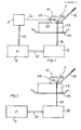
- FIG. 1 shows a schematic diagram of a block diagram the present machine, which is preferably is a Haittlervoriques 1 whose worktop 12 in a conventional manner via a vibration device 13 is placed in vibration or vibrations.
- the Vibration device 13 is thereby by the internal combustion engine 11, which is preferably a diesel engine, driven.
- the flywheel 17 of the internal combustion engine 11th is, as shown schematically, a pneumatic Starting device 3 with a pneumatic motor via a Shaft 32 mechanically connectable.
- the pneumatic starter device 3 is connected via a pressure line 31 to a pressure reservoir 4 in connection, via a further pressure line 51 is connected to a compressor 5, for example via the schematically illustrated mechanical shaft 52 with a Output of the internal combustion engine 11 is in communication.
- the compressor 5 other than mechanical, for example, hydraulically or electrically by the internal combustion engine 11 to drive, with a corresponding output of the Internal combustion engine 11 then via a hydraulic line or a electrical line is connected to the compressor 5, the the mechanical shaft 52 replaced.
- the pneumatic starter device 3, the pressure reservoir 4 and the compressor 5 and the corresponding pressure lines 31, 51 and the line 52 are part of the Rüttlervoruze 1 and arranged at this.
- the mechanical connection between the shaft 32 of the engine the pneumatic starter device 3 with the flywheel 17 of the internal combustion engine 11 is preferably carried out via a known pinion / gear unit, not in the figure is shown and for starting the internal combustion engine 11 for Intervention is broken. After a successful startup operation the said pinion / gear unit is disconnected again.
- the internal combustion engine 11 also a known manual starter, preferably in the form of a crank drive, as needed is mechanically connected to the starter shaft 14 and its function will be explained in more detail below.
- a known manual starter preferably in the form of a crank drive
Landscapes
- Engineering & Computer Science (AREA)
- Chemical & Material Sciences (AREA)
- Combustion & Propulsion (AREA)
- Mechanical Engineering (AREA)
- General Engineering & Computer Science (AREA)
- Road Paving Machines (AREA)
- Apparatuses For Generation Of Mechanical Vibrations (AREA)
- Supercharger (AREA)
Abstract
Description
Claims (9)
- Maschine mit einem Brennkraftmotor (11) und einer Anlasservorrichtung (3), insbesondere Rüttlervorrichtung zur Verdichtung eines Untergrundes, bei der eine Arbeitsplatte (12) durch eine Vibrationseinrichtung (13), die durch den Brennkraftmotor (11) angetrieben wird, in Schwingungen versetzbar ist,
dadurch gekennzeichnet, dass
eine pneumatische Anlasservorrichtung (3) vorgesehen und zum Anlassen des Brennkraftmotors (11) mit dem Schwungrad (17) desselben verbindbar ist und dass ein Druckreservoir (4) für einen Druck (P) zum Antrieb der pneumatischen Anlasservorrichtung (3) vorgesehen und mit dieser verbindbar ist, wobei der Brennkraftmotor (11) zur Erzeugung des Druckes (P) in dem Druckreservoir (4) dient. - Maschine nach Anspruch 1,
dadurch gekennzeichnet, dass
der Brennkraftmotor (11) einen Kompressor (5) antreibt, der den Druck (P) in dem Druckreservoir (4) aufbaut. - Maschine nach Anspruch 2,
dadurch gekennzeichnet, dass
die Brennkraftmaschine (11) den Kompressor (5) mechanisch, hydraulisch oder elektrisch antreibt. - Maschine nach einem der Ansprüche 1 bis 3,
dadurch gekennzeichnet, dass
die pneumatische Anlasservorrichtung (3) mit der Hilfe einer Kupplungseinrichtung mit der Schwungscheibe (17) des Brennkraftmotors (11) verbindbar ist. - Maschine nach Anspruch 4,
dadurch gekennzeichnet, dass
die Kupplungseinrichtung eine Ritzel/Zahnradeinheit ist. - Maschine nach Anspruch 1,
dadurch gekennzeichnet, dass
die pneumatische Anlasservorrichtung (30) permanent mit der Schwungscheibe (17) des Brennkraftmotors (11) verbunden ist und nach einer Anlassoperation dadurch als Druckgenerator wirkt, dass ihr pneumatischer Motor den Druck (P) im Druckreservoir (4) erzeugt. - Maschine nach einem der Ansprüche 1 bis 6,
dadurch gekennzeichnet, dass
die Brennkraftmaschine (11) ein Dieselmotor ist. - Maschine nach einem der Ansprüche 1 bis 7,
dadurch gekennzeichnet, dass
der Brennkraftmotor (11) zum manuellen Starten des Brennkraftmotors (11) einen mit der Anlasserwelle (14) des Brennkraftmotors (11) mechanisch verbindbaren Kurbelantrieb aufweist. - Verfahren zum Starten einer Maschine nach Anspruch 8,
dadurch gekennzeichnet, dass
ein erster Startvorgang manuell durch Betätigen des Kurbelantriebes ausgeführt wird, wobei der Brennkraftmotor (11) nach dem erstmaligen Startvorgang in dem Druckreservoir (4) den Druck (P) erzeugt, der für nachfolgende Startvorgänge zum Antrieb der pneumatischen Anlasservorrichtung (30) erforderlich ist.
Applications Claiming Priority (2)
| Application Number | Priority Date | Filing Date | Title |
|---|---|---|---|
| DE200410006715 DE102004006715A1 (de) | 2004-02-11 | 2004-02-11 | Maschine mit einem Brennkraftmotor und einer pneumatischen Anlasservorrichtung |
| DE102004006715 | 2004-02-11 |
Publications (2)
| Publication Number | Publication Date |
|---|---|
| EP1564402A2 true EP1564402A2 (de) | 2005-08-17 |
| EP1564402A3 EP1564402A3 (de) | 2006-11-22 |
Family
ID=34684003
Family Applications (1)
| Application Number | Title | Priority Date | Filing Date |
|---|---|---|---|
| EP05002809A Withdrawn EP1564402A3 (de) | 2004-02-11 | 2005-02-10 | Maschine mit einem Brennkraftmotor und einer pneumatischen Anlasservorrichtung |
Country Status (2)
| Country | Link |
|---|---|
| EP (1) | EP1564402A3 (de) |
| DE (1) | DE102004006715A1 (de) |
Family Cites Families (3)
| Publication number | Priority date | Publication date | Assignee | Title |
|---|---|---|---|---|
| US1066649A (en) * | 1912-04-22 | 1913-07-08 | Harry Parker | Starting device for automobiles. |
| US1593810A (en) * | 1922-11-28 | 1926-07-27 | Leroy F Hammond | Compressed-air automobile starter |
| CH361542A (de) * | 1958-01-21 | 1962-04-15 | Wacker Hermann | Als Stampfgerät oder Rüttelgerät oder Schlaggerät ausgebildete Arbeitsvorrichtung mit Antriebsmotor |
-
2004
- 2004-02-11 DE DE200410006715 patent/DE102004006715A1/de not_active Withdrawn
-
2005
- 2005-02-10 EP EP05002809A patent/EP1564402A3/de not_active Withdrawn
Also Published As
| Publication number | Publication date |
|---|---|
| EP1564402A3 (de) | 2006-11-22 |
| DE102004006715A1 (de) | 2005-08-25 |
Similar Documents
| Publication | Publication Date | Title |
|---|---|---|
| EP4196647B1 (de) | Autobetonpumpe | |
| EP2216151B1 (de) | Trommelantrieb für einen Fahrmischer | |
| DE1780018A1 (de) | Pumpe fuer Beton oder andere dickfluessige,breiige Massen | |
| DE102012024452A1 (de) | Baumaschine oder Landmaschine mit einer rotierenden Arbeitseinrichtung und Verfahren zum Antreiben der rotierenden Arbeitseinrchtung | |
| DE102008028547A1 (de) | Hydraulischer Abtriebswellengenerator | |
| EP1120557A2 (de) | Betriebseinrichtung für eine Brennkraftmaschine eines Kraftfahrzeuges mit einem Starter | |
| DE102016221311A1 (de) | Landwirtschaftliches Nutzfahrzeug mit Zapfwelle und Verfahren zum Antrieb der Zapfwelle | |
| DE102005039868A1 (de) | Doppelantriebpumpe mit zwei Ketten und Rollenkupplung und Verfahren | |
| WO2018036730A1 (de) | Pumpstation für eine pipeline und verfahren zum starten eines verbrennungsmotors in einer pumpstation | |
| DE10360855A1 (de) | Einen Elektromotor verwendende Hydraulikantriebsvorrichtung | |
| DE3041867A1 (de) | Kraftfahrzeug, insbesondere personenkraftfahrzeug | |
| DE102007010343A1 (de) | Hybridfahrzeug mit Splitmotor | |
| EP1355062A2 (de) | Starteinrichtung | |
| DE2826298A1 (de) | Anordnung in einer arbeitsmaschine | |
| DE102018217849A1 (de) | Getriebe und Antriebssystem eines Kraftfahrzeugs | |
| EP1564402A2 (de) | Maschine mit einem Brennkraftmotor und einer pneumatischen Anlasservorrichtung | |
| WO2010052047A1 (de) | Starteranordnung mit nebenaggregateantrieb | |
| DE3245663A1 (de) | Elektrische anlaufsteuerung | |
| DE10141740B4 (de) | Kraftfahrzeug mit einem Brennstoffzellensystem | |
| DE2402834A1 (de) | Hydraulikbagger mit antrieb durch mehr als eine energieart | |
| DE102012020821B4 (de) | Notantrieb für ein Baugerät und Verfahren zum Betrieb des Notantriebs | |
| EP3550083B1 (de) | Baumaschine | |
| DE102020126490A1 (de) | Verfahren und Vorrichtung zur Ansteuerung einer elektrischen Maschine | |
| DE102013006861A1 (de) | Kompressorsystem mit Kupplung | |
| DE102019133856A1 (de) | Antriebseinheit und Verfahren zum Betrieb der Antriebseinheit |
Legal Events
| Date | Code | Title | Description |
|---|---|---|---|
| PUAI | Public reference made under article 153(3) epc to a published international application that has entered the european phase |
Free format text: ORIGINAL CODE: 0009012 |
|
| AK | Designated contracting states |
Kind code of ref document: A2 Designated state(s): AT BE BG CH CY CZ DE DK EE ES FI FR GB GR HU IE IS IT LI LT LU MC NL PL PT RO SE SI SK TR |
|
| AX | Request for extension of the european patent |
Extension state: AL BA HR LV MK YU |
|
| RIN1 | Information on inventor provided before grant (corrected) |
Inventor name: STOLL, MARKUS |
|
| PUAL | Search report despatched |
Free format text: ORIGINAL CODE: 0009013 |
|
| AK | Designated contracting states |
Kind code of ref document: A3 Designated state(s): AT BE BG CH CY CZ DE DK EE ES FI FR GB GR HU IE IS IT LI LT LU MC NL PL PT RO SE SI SK TR |
|
| AX | Request for extension of the european patent |
Extension state: AL BA HR LV MK YU |
|
| AKX | Designation fees paid | ||
| STAA | Information on the status of an ep patent application or granted ep patent |
Free format text: STATUS: THE APPLICATION IS DEEMED TO BE WITHDRAWN |
|
| 18D | Application deemed to be withdrawn |
Effective date: 20070523 |
|
| REG | Reference to a national code |
Ref country code: DE Ref legal event code: 8566 |