EP1564332A2 - Fraiseuse et procédé pour travailler le sol - Google Patents
Fraiseuse et procédé pour travailler le sol Download PDFInfo
- Publication number
- EP1564332A2 EP1564332A2 EP05002009A EP05002009A EP1564332A2 EP 1564332 A2 EP1564332 A2 EP 1564332A2 EP 05002009 A EP05002009 A EP 05002009A EP 05002009 A EP05002009 A EP 05002009A EP 1564332 A2 EP1564332 A2 EP 1564332A2
- Authority
- EP
- European Patent Office
- Prior art keywords
- channel
- transport
- suction
- milling
- channel section
- Prior art date
- Legal status (The legal status is an assumption and is not a legal conclusion. Google has not performed a legal analysis and makes no representation as to the accuracy of the status listed.)
- Granted
Links
Images

Classifications
-
- E—FIXED CONSTRUCTIONS
- E01—CONSTRUCTION OF ROADS, RAILWAYS, OR BRIDGES
- E01C—CONSTRUCTION OF, OR SURFACES FOR, ROADS, SPORTS GROUNDS, OR THE LIKE; MACHINES OR AUXILIARY TOOLS FOR CONSTRUCTION OR REPAIR
- E01C23/00—Auxiliary devices or arrangements for constructing, repairing, reconditioning, or taking-up road or like surfaces
- E01C23/06—Devices or arrangements for working the finished surface; Devices for repairing or reconditioning the surface of damaged paving; Recycling in place or on the road
- E01C23/08—Devices or arrangements for working the finished surface; Devices for repairing or reconditioning the surface of damaged paving; Recycling in place or on the road for roughening or patterning; for removing the surface down to a predetermined depth high spots or material bonded to the surface, e.g. markings; for maintaining earth roads, clay courts or like surfaces by means of surface working tools, e.g. scarifiers, levelling blades
- E01C23/085—Devices or arrangements for working the finished surface; Devices for repairing or reconditioning the surface of damaged paving; Recycling in place or on the road for roughening or patterning; for removing the surface down to a predetermined depth high spots or material bonded to the surface, e.g. markings; for maintaining earth roads, clay courts or like surfaces by means of surface working tools, e.g. scarifiers, levelling blades using power-driven tools, e.g. vibratory tools
- E01C23/088—Rotary tools, e.g. milling drums
-
- B—PERFORMING OPERATIONS; TRANSPORTING
- B28—WORKING CEMENT, CLAY, OR STONE
- B28D—WORKING STONE OR STONE-LIKE MATERIALS
- B28D7/00—Accessories specially adapted for use with machines or devices of the preceding groups
- B28D7/02—Accessories specially adapted for use with machines or devices of the preceding groups for removing or laying dust, e.g. by spraying liquids; for cooling work
-
- E—FIXED CONSTRUCTIONS
- E01—CONSTRUCTION OF ROADS, RAILWAYS, OR BRIDGES
- E01C—CONSTRUCTION OF, OR SURFACES FOR, ROADS, SPORTS GROUNDS, OR THE LIKE; MACHINES OR AUXILIARY TOOLS FOR CONSTRUCTION OR REPAIR
- E01C2301/00—Machine characteristics, parts or accessories not otherwise provided for
- E01C2301/50—Methods or devices for preventing dust by spraying or sucking
Definitions
- the invention relates to a milling machine for processing ground surfaces, in particular roadways, according to the preamble of claim 1, and a method to dispose of dust generated during milling and steaming on a milling machine according to the preamble of claim 9.
- Such milling machines are self-propelled and are also called street milling machines designated.
- a front loading router according to the preamble of claim 1 is known from DE 102 23 819 A1.
- the well-known road milling machines have a self-propelled Chassis with a chassis consisting of several wheel drives or several crawler drives.
- the chassis carries a machine frame, in which a milling drum transverse to Direction is stored.
- the milling drum is usually of a housing surrounded, in which the pointing in the direction of travel wall as a cover is formed with a passage opening for the milled material. That from the milling drum processed material is taken from a first conveyor belt, that the processed material at the front end of the milling machine transferred to a discharge conveyor for transport to a loading area of a truck in the inclination and is laterally pivotable.
- the one at the back End cyclone separator can only segregate the coarser particles not the respirable particulate matter, so the arrangement of the air outlet arranged at the rear end of the road milling machine too close to the control station is. This causes the dusts and fumes at the rear end of the milling machine blown off near the helm. Furthermore, the fan transports the dust-laden air, allowing high wear to a short life of the blower leads.
- the suction device has a suction channel arranged axial fan, due to the high load with Dusts and sharp-edged particles are subject to severe wear and tear ultimately results in reduced air output and bearing damage.
- the fan blades of the axial fan are due to the impact and the deflection of the high-speed particles supplied strong worn and damaged.
- Aspirating larger particles and small stones are also other parts of the blower mechanically damaged, with at Damage to the fan blades often also imbalances occur in the further operation may lead to bearing damage.
- a repair is disadvantageous that the fan is located in a hard to reach place and therefore a Repair leads to a major business interruption.
- the fan due transport of dusts and sharp particles the fan be designed so that the game between the fan blades and the walls the blower is larger, so that the air performance and efficiency of such a fan for dust and particle laden air is lower.
- the invention has the object underlying, a milling machine of the type mentioned, and a method to dispose of dusts and vapors, with little mechanical Effort and with higher efficiency in the milling process and the Transport process resulting dusts and vapors, especially the respirable Dust, can be sucked off and disposed of while doing the Service life of the suction device can be considerably extended.
- the invention advantageously provides that the suction device a suction fan, a separator for solids and a suction channel which is at the rear in the material transport direction channel section connected to the suction fan downstream of the separator is arranged and that the deposition device, the deposited Solids on the transport device in a front in material transport direction Channel section, or disposed of in a collection and the purified Air blows off to the outside.
- the invention enables a simple construction, in which the construction of a Road milling machine does not basically need to be changed, so also a retrofit existing road milling is possible. Because of the suction fan the suction device is arranged behind the separator, the Suction fan operated on the clean air side, so that the suction fan a higher Life has.
- the invention not only allows a significantly increased Service life of the suction fan, but also a significant improvement the air quality in the environment of the control station.
- the clean air is blown off directly into the open air.
- the secluded Solids can either be on the transport device in the front channel section or disposed of in a collection facility.
- Such a collector may e.g. from an air-permeable dust bag exist, which decreased in business interruptions of the road milling machine can be used to dispose of the separated solids.
- the separating device consists of a filter device and that of the forming in the filter device filter cake on the transport device in the front channel section or in the collecting device is disposable.
- a filter device has the Advantage that these high efficiency in terms of breathable dusts and that the separated solids compacted into a filter cake which is easier to dispose of without disposal
- dusts can be generated to a considerable extent.
- binders e.g. a hydrous one Spray mist to compress even more, so when disposed of at all dusts can no longer arise.
- the filter cake may be removed from the filter device at predetermined time intervals or automatically removed at a predetermined pressure loss. there it is also possible, the filter device only during breaks, e.g. at To clean a tool change, if the filter capacity designed accordingly is. Another way to add the filter cake from the filter device remove, every time you change the front of the road milling machine truck and the associated short-term work break.
- the filter device is then for cleaning, for example, with a vibration or acted upon by a pulse-like counterpressure.
- the front channel section from the rear channel section with release means for the most part Locking an air flow is separated without the transport of the milled off Material is obstructed.
- the separation of the channel into one Front and a rear channel section ensures that the over the Suction duct in the material transport direction extracted dust-laden air only off the rear, dust-laden channel section is sucked, and that no Air flow in the front channel section against the Materialtransportides can arise.
- the division is made by release agents, on the one hand not hinder the transport of the milled material and on the other hand a Prevent air flow against the material transport direction.
- the transport device at least one Has conveyor belt with a conveyor belt, and that sealing means for the Channel out against the conveyor belt and against the housing of the conveyor belt consist of sealing hoods.
- the hoods thus form together with the Conveyor belt or together with the housing of the conveyor belt a closed Channel, so that the milled material, the transport device circumferentially passes completely enclosed. That way you can go along of the duct do not emit dusts or vapors to the outside. Minor gaps in the Channel course are irrelevant, since the channel is under negative pressure, so that contaminated air can not escape at any points of leakage, but at most air is sucked.
- a second front transport means may be the milled material at the end take over the first rear transport device at a transfer point.
- the transfer point between the first and the second transport device circumferentially sealed with flexible sealing means, the at least one of the transport devices are attached. It becomes a consistent one Channel formed, which contains both transport facilities.
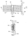
- the separating means may consist of a flexible flap, which is the rear channel section the transport device against air inlet against the material transport device closes.
- the negative pressure in the rear channel section reinforces the seal by sucking the flap on the conveyor belt.
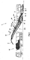
- FIG. 1 A road milling machine 1 for working roadways in the embodiment a front-end loader is shown in FIG. It is understood that the Invention is applicable to other types of milling machines, with at least a transport device 14, 18 are provided.
- the road milling machine 1 is used for milling off ground surfaces, in particular Roads made of asphalt, concrete o. The like.
- the road milling machine 1 has a Chassis with, for example, four crawlers 4 on which the machine frame 2 carries. It is understood that the crawler tracks through wheel drives can be substituted in whole or in part.
- a milling drum 8 mounted, which extends transversely to the direction of travel. The attitude The milling depth is preferably carried out by means of the height adjustment of the chain drives 4.
- the road milling machine 1 shown in Fig. 1 is also called Front loader road milling machine called, as they the milled material in the direction of travel transported forward to a transport vehicle 10.
- a first consisting of a conveyor belt transport device 14 with a conveyor belt 15 in a shaft 9 of the machine frame 2, which extends at an inclination angle in the machine frame 2.
- the first transporting device 14 conveys the milled material 3 the conveyor belt 15 to a second, preferably also a conveyor belt 19th having transporting device 18.
- the second transporting device 18 is adjustable in height via an adjustable inclination angle and can additionally be pivoted laterally by, for example ⁇ 30 °, so that in addition to the Lane of the road milling machine stationary transport vehicles 10 loaded can be.
- the conveyor belts 15, 19 is also the use of in a conveyor arranged screw conveyor possible.
- the milling drum 8 is usually surrounded by a roller box 58 at the facing in the direction of travel wall as a shield 52 with a passage opening 56 is formed for the milled material.
- the milling drum 8 is provided with helically arranged chisel tools, which are arranged so that the milled material 3 to the passage opening 56th is transported in the shield 52.
- Roller box 58 is a close to the milled ground surface final Wall 60 of the roller box 58 provided the milled soil surface peels off so that no fragments of the milled material 3 on the milled soil surface remain.
- the wall 60 is with its lower edge hydraulically pressed against the ground surface to ensure the best possible sealing to achieve.
- On machine frame 2 is designated as a band shoe 50 band protection and Support device mounted height adjustable in a guide.
- the belt shoe 50 takes up the rear end of the first transport device 14.
- the passage opening 56 of the roller box 58 forms a first transfer point 5, at which the milled material from the milling drum 8 on the first conveyor 14th is handed over.
- the control station is located in the embodiment of FIG. 1 above the Milling roller 8, but can as usual in road milling machines in the rear or front portion of the machine frame 2 may be arranged.
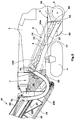
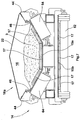
- FIGS. 5 and 6 show in detail the first transport device 14.
- the transport device 14 is arranged in a preferably centrally Shaft 9 of the machine frame 2 is fixed and can easily from the belt shoe 50 are dismantled for maintenance purposes and through the shaft 9 therethrough get extended.
- the transport device 14 with the conveyor belt 15 has a hood 22 which together with the upper run 15a of the conveyor belt 15 a channel section 16 a of a channel 16 extending from the roller box 58 to the end of second transport means 18 extends.
- Elastic lips 46 can on the hood brackets 44 on both sides of the Be fastened conveyor belt and the upper run 15 a of the conveyor belt 15 in Touch edge area over the entire length of the upper run 15a.
- the second transport device 18 with a hood 26 be provided.
- the entire channel 16 dustproof and gas-tight be sealed against the environment, even if the sealing of the Front channel section 16b is only really necessary if one more Noteworthy dust formation in the front channel section 16b even detectable is.
- the hood 22 of the first transport device 14 at least one nozzle 23, 23 a, 23 b, to the at least one suction channel 24 is connectable.
- the suction channel 24 of two suction hoses 24a, 24b formed by the nozzle 23a, 23b lead to the inlet side of a filter housing of a filter device 25, preferably in the region of the front channel portion 16b on the hood 26 of the front transport device 18 is placed.
- the filter device 25 is preferably composed of several, e.g. ten filter cartridges 31, preferably are connected in parallel to form a large filter surface.
- the Suction fan 28 is arranged on the output side of the clean air side and is characterized only charged with clean air.
- An exhaust pipe 29 allows to blow off the cleaned exhaust air directly into the open air. Alternatively, the clean air on the front end of the filter device 25 or at the front end of the front Transport device 18 are blown off.
- the suction fan 28 allows a high air flow and thus generates a corresponding high negative pressure in the rear channel section 16a and in the milling drum 8 surrounding roller box 58. The dusts arising during the milling process and vapors are therefore reliable and with high efficiency over the Suction duct 24, 24a, 24b sucked.
- the flaps 36 are provided with slots.
- several Flaps 36 arranged one behind the other to provide an improved air seal between to reach the channel sections 16a, 16b ( Figure 5).
- the preferably consisting of flaps 36 release agent within the channel 16 also elsewhere, e.g. in material transport direction behind the second transfer point 7 in the region of the second transport device 18 may be arranged.
- the rear channel section 16a thus ends at the release means in the material transport device downstream of the transfer point 7 are arranged.
- the conveyor belt 15 is, as best seen in Fig. 7, via support rollers 62,64 out, wherein the upper run 15a has a substantially U-shaped groove forms by the support rollers 64 are inclined accordingly.
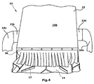
- the lower support roller 62 supports the lower run 15b of the conveyor belt 15. As shown in FIGS. 3 and Figure 4 shows, there are 15 webs on the surface of the conveyor belt 17, which improve the entrainment of the milled material 3 on the conveyor belt 15.
- the milled material 3 at the second transfer point 7 into a receiving hopper 35 of the second Passing conveyor 18, whereby the milled material 3 on the Conveyor belt 19 is conveyed to the discharge end and the transport vehicle 10 is disposed of.
- the Filter cake the filter device 25 via a flap 37 in the filter housing 33rd be disposed of (Fig. 5).
- the filter cake in one of a Dust collection bag existing collecting device 39 are filled (Fig. 6), which is attached to an opening of the filter housing 33.
- a flap 37 in the bottom of the filter housing 33rd be provided.
- the transition point at the transfer point 7 is made of flexible mats 30 existing Sealing means enclosed, so that the first transport device 14 and the second transport device 18 in a material transport direction form continuous circumferentially sealed channel 16.
- Filter device 25 is set at intervals selectable by the operator, e.g. during business interruptions, such as Change of the preceding driver Truck 10 or tool change to manual command, e.g. by vibration or by applying a pressure pulse in the counterflow direction cleaned.
- the seated on the filter cartridges 31 filter cake away.
- the filter cake also depending on with increasing operating time of the filter device 25 forming pressure loss, or be automatically cleaned after predetermined time intervals.
- Filter cake removed from the filter cartridges 31 may be due to inclination the bottom of the filter housing 33 to the rear end of the filter housing 33 slip, where, for example, a flap 37 and the receiving hopper 35 can be disposed of on the front transport device 18. That's it also possible to compress the filter cake additionally by a spray and cohesion of the deposited particles through the spray increase.
- the filter cake behind the release agents the front transport device 18 abandoned.
- suction hoses 24a, 24b of the suction channel 24 occur, as shown in FIG. 2, from two opposite sides in the filter housing 33, wherein the Filter cartridges 31 from the outside charged with the dust and vapor laden air become.
Landscapes
- Engineering & Computer Science (AREA)
- Mechanical Engineering (AREA)
- Mining & Mineral Resources (AREA)
- Architecture (AREA)
- Civil Engineering (AREA)
- Structural Engineering (AREA)
- Road Repair (AREA)
- Crushing And Grinding (AREA)
Applications Claiming Priority (2)
| Application Number | Priority Date | Filing Date | Title |
|---|---|---|---|
| DE102004007716A DE102004007716B3 (de) | 2004-02-16 | 2004-02-16 | Fräsmaschine sowie Verfahren zum Bearbeiten von Bodenoberflächen |
| DE102004007716 | 2004-02-16 |
Publications (3)
| Publication Number | Publication Date |
|---|---|
| EP1564332A2 true EP1564332A2 (fr) | 2005-08-17 |
| EP1564332A3 EP1564332A3 (fr) | 2006-03-08 |
| EP1564332B1 EP1564332B1 (fr) | 2009-10-21 |
Family
ID=34585416
Family Applications (1)
| Application Number | Title | Priority Date | Filing Date |
|---|---|---|---|
| EP05002009A Expired - Lifetime EP1564332B1 (fr) | 2004-02-16 | 2005-02-01 | Fraiseuse et procédé pour travailler le sol |
Country Status (4)
| Country | Link |
|---|---|
| US (1) | US7219964B2 (fr) |
| EP (1) | EP1564332B1 (fr) |
| AT (1) | ATE446415T1 (fr) |
| DE (2) | DE102004007716B3 (fr) |
Cited By (1)
| Publication number | Priority date | Publication date | Assignee | Title |
|---|---|---|---|---|
| CN110258258A (zh) * | 2019-07-09 | 2019-09-20 | 三门前庭机械科技有限公司 | 一种无烟排放的沥青铺设装置 |
Families Citing this family (36)
| Publication number | Priority date | Publication date | Assignee | Title |
|---|---|---|---|---|
| US7942605B2 (en) * | 2007-08-24 | 2011-05-17 | Hall David R | Milling drum |
| DE102008008260B4 (de) | 2008-02-08 | 2010-09-09 | Wirtgen Gmbh | Steuerung einer Gewinnungsmaschine und Gewinnungsmaschine |
| CN101970759B (zh) * | 2008-03-12 | 2014-05-07 | 马林公司 | 用于磨削路面的改进的刨路机 |
| EP2350390B1 (fr) * | 2008-10-21 | 2012-09-05 | Marini S.p.A. | Machine à niveler les chaussées pour fraiser les surfaces de roulement |
| DE102009057936A1 (de) | 2009-12-16 | 2011-06-22 | Zuur, Richard Bastiaan, 9695 | Fahrbare Vorrichtung zur Herstellung von Fußbodenschlitzen für Heizungsrohre |
| US20110278907A1 (en) * | 2010-05-12 | 2011-11-17 | Diamond Products, Limited | Concrete Profiler With Vacuum System |
| US20120280558A1 (en) | 2011-05-06 | 2012-11-08 | Hall David R | Foam Configured to Suppress Dust on a Surface to be Worked |
| DE102011109450A1 (de) * | 2011-08-04 | 2013-02-07 | Bomag Gmbh | Fräsrotor zur Bearbeitung von Bodenmaterial sowie Bodenbearbeitungsmaschine mit einem derartigen Rotor |
| DE102012203649A1 (de) * | 2012-03-08 | 2013-09-12 | Wirtgen Gmbh | Selbstfahrende Straßenfräsmaschine zum Bearbeiten von Straßenoberflächen, insbesondere Großfräse |
| CN102619158B (zh) * | 2012-04-17 | 2016-05-04 | 陕西长大实业有限公司 | 路面铣刨机 |
| US8985701B2 (en) | 2012-07-12 | 2015-03-24 | Caterpillar Paving Products Inc. | Cold planer having multi-inlet exhaust system |
| DE102012215013A1 (de) | 2012-08-23 | 2014-02-27 | Wirtgen Gmbh | Selbstfahrende Fräsmaschine, sowie Verfahren zum Abladen von Fräsgut |
| DE102012215005A1 (de) | 2012-08-23 | 2014-02-27 | Wirtgen Gmbh | Selbstfahrende Fräsmaschine, sowie Verfahren zum Lenken einer selbstfahrenden Fräsmaschine |
| DE102012022879B4 (de) * | 2012-08-24 | 2015-10-01 | Bomag Gmbh | Baumaschine mit einer Staubabsaugung, Einrichtung zur Staubabsaugung für eine Baumaschine sowie Verfahren zum Absaugen von Staub bei einer Baumaschine |
| DE102012019016A1 (de) * | 2012-09-26 | 2014-04-10 | Bomag Gmbh | Materialübergabevorrichtung für eine Bodenfräsmaschine und Bodenfräsmaschine, insbesondere Straßenfräse mit einer solchen Materialübergabevorrichtung |
| US9273433B2 (en) | 2013-10-16 | 2016-03-01 | Roadtec, Inc. | Method and apparatus for controlling dust emissions with temperature control |
| DE102013226981B4 (de) * | 2013-12-20 | 2016-09-29 | Wirtgen Gmbh | Baumaschine, sowie ein Verfahren zum Abfräsen und Abstransportieren eines abgefrästen Materialstroms einer Baumaschine |
| CN104099899B (zh) * | 2014-07-17 | 2015-12-30 | 中国水利水电第十一工程局有限公司 | 一种遥控式履带行走混凝土伸缩缝自动注胶机 |
| DE102014216603B4 (de) | 2014-08-21 | 2018-02-22 | Wirtgen Gmbh | Selbstfahrende Fräsmaschine, sowie Verfahren zum Abladen von Fräsgut |
| DE102014216763B4 (de) | 2014-08-22 | 2018-07-26 | Wirtgen Gmbh | Selbstfahrende Fräsmaschine, sowie Verfahren zum Abladen von Fräsgut |
| DE102014216713B4 (de) | 2014-08-22 | 2018-09-06 | Wirtgen Gmbh | Selbstfahrende Fräsmaschine, sowie Verfahren zum Abladen von Fräsgut |
| US9873142B2 (en) | 2015-05-04 | 2018-01-23 | Caterpillar Paving Products Inc. | Cold planer exhaust system with access doors |
| DE102016003895A1 (de) * | 2016-03-31 | 2017-10-05 | Bomag Gmbh | Bodenfräsmaschine, insbesondere Straßenfräse, zum Abtragen von Bodenmaterial sowie Verfahren zum Betrieb einer Bodenfräsmaschine |
| DE102016009516A1 (de) | 2016-08-04 | 2018-02-08 | Bomag Gmbh | Straßenfräse |
| US20170009410A1 (en) * | 2016-09-22 | 2017-01-12 | Caterpillar Paving Products Inc. | Ventilation system for cold planer |
| DE102016222589B4 (de) | 2016-11-16 | 2020-01-16 | Wirtgen Gmbh | Selbstfahrende Fräsmaschine, sowie Verfahren zum Steuern einer selbstfahrenden Fräsmaschine |
| DE102017220869A1 (de) | 2017-11-22 | 2019-05-23 | Wirtgen Gmbh | Selbstfahrende Fräsmaschine, Verfahren zum automatischen Beladen eines Transportmittels mit Fräsgut, sowie Straßen- oder Bodenbearbeitungseinheit |
| CN108797291A (zh) * | 2018-08-31 | 2018-11-13 | 王凌 | 一种路面铣刨机除尘、除铣刨废料装置 |
| DE102019104218A1 (de) | 2019-02-19 | 2020-08-20 | Wirtgen Gmbh | Arbeitszug, umfassend eine Bodenbearbeitungsmaschine und ein weiteres Fahrzeug sowie eine automatisierte Abstandsüberwachung |
| DE102019132886A1 (de) | 2019-12-03 | 2021-06-10 | Wirtgen Gmbh | Bodenbearbeitungsmaschine mit Staubabsaugung und rotierbaren Filterkartuschen |
| DE102019132892A1 (de) | 2019-12-03 | 2021-06-10 | Wirtgen Gmbh | Bodenbearbeitungsmaschine mit gefilterter Staubabsaugung mit elastisch verformbarem Filtergehäuse |
| DE102019132889A1 (de) | 2019-12-03 | 2021-06-10 | Wirtgen Gmbh | Bodenbearbeitungsmaschine mit Staubabsaugung mit wahlweiser Filterung der abgesaugten staubbelasteten Luft |
| DE102020005666A1 (de) * | 2020-09-16 | 2022-03-17 | Bomag Gmbh | Bodenfräsmaschine mit staubabsaugungseinrichtung und wartungstunnel sowie verfahren |
| CN112726357A (zh) * | 2020-12-25 | 2021-04-30 | 黄宇 | 一种沥青路面铣刨装置 |
| CN113026504B (zh) * | 2021-03-19 | 2022-07-01 | 山东省旗舰建设集团有限公司 | 建筑施工用混凝土铣刨设备 |
| DE102022206278A1 (de) * | 2022-06-22 | 2023-12-28 | Bomag Gmbh | Bodenfräsmaschine, insbesondere Straßenfräse, Recycler oder Stabilisierer, und Verfahren zum Betrieb einer Staubabsaugeinrichtung einer Bodenfräsmaschine |
Citations (1)
| Publication number | Priority date | Publication date | Assignee | Title |
|---|---|---|---|---|
| DE10223819A1 (de) | 2002-05-28 | 2003-12-24 | Wirtgen Gmbh | Fräsmaschine zum Beareiten von Bodenoberflächen, sowie Verfahren zum Erzeugen von während der Fräsbearbeitung entstehenden Stäuben und Dämpfen an einer Fräsmaschine |
Family Cites Families (7)
| Publication number | Priority date | Publication date | Assignee | Title |
|---|---|---|---|---|
| USRE24004E (en) * | 1955-05-17 | Collapsible mining head | ||
| US2100178A (en) * | 1936-05-11 | 1937-11-23 | Pittsburgh Coal Company | Coal mining machine |
| DE2528418A1 (de) * | 1975-06-26 | 1977-01-20 | Errut Prod Ltd | Vorrichtung zum schneiden von nuten, insbesondere in strassenbelaege |
| US4561145A (en) * | 1984-02-16 | 1985-12-31 | Latham Winchester E | Continuous sweep for road planing and milling machines |
| US5063713A (en) * | 1990-12-20 | 1991-11-12 | Accent Stripe Inc. | Surface abrading and particle collection device |
| ITVI980132A1 (it) * | 1998-07-09 | 2000-01-09 | Bitelli Spa | Dispositivo di aspirazione e trattamento delle polveri prodotte dalle macchine scarificatrici |
| US6733086B1 (en) * | 2002-03-15 | 2004-05-11 | Ri Properties, Inc. | Vacuum system for milling machine |
-
2004
- 2004-02-16 DE DE102004007716A patent/DE102004007716B3/de not_active Expired - Fee Related
-
2005
- 2005-02-01 AT AT05002009T patent/ATE446415T1/de not_active IP Right Cessation
- 2005-02-01 EP EP05002009A patent/EP1564332B1/fr not_active Expired - Lifetime
- 2005-02-01 DE DE502005008355T patent/DE502005008355D1/de not_active Expired - Lifetime
- 2005-02-15 US US11/057,838 patent/US7219964B2/en not_active Expired - Lifetime
Patent Citations (1)
| Publication number | Priority date | Publication date | Assignee | Title |
|---|---|---|---|---|
| DE10223819A1 (de) | 2002-05-28 | 2003-12-24 | Wirtgen Gmbh | Fräsmaschine zum Beareiten von Bodenoberflächen, sowie Verfahren zum Erzeugen von während der Fräsbearbeitung entstehenden Stäuben und Dämpfen an einer Fräsmaschine |
Cited By (2)
| Publication number | Priority date | Publication date | Assignee | Title |
|---|---|---|---|---|
| CN110258258A (zh) * | 2019-07-09 | 2019-09-20 | 三门前庭机械科技有限公司 | 一种无烟排放的沥青铺设装置 |
| CN110258258B (zh) * | 2019-07-09 | 2021-06-08 | 山东广通汽车科技股份有限公司 | 一种无烟排放的沥青铺设装置 |
Also Published As
| Publication number | Publication date |
|---|---|
| EP1564332A3 (fr) | 2006-03-08 |
| US20050179309A1 (en) | 2005-08-18 |
| EP1564332B1 (fr) | 2009-10-21 |
| ATE446415T1 (de) | 2009-11-15 |
| US7219964B2 (en) | 2007-05-22 |
| DE102004007716B3 (de) | 2005-06-16 |
| DE502005008355D1 (de) | 2009-12-03 |
Similar Documents
| Publication | Publication Date | Title |
|---|---|---|
| DE102004007716B3 (de) | Fräsmaschine sowie Verfahren zum Bearbeiten von Bodenoberflächen | |
| EP1507925B1 (fr) | Unite et procede d'aspiration pour eliminer la poussiere sur des fraiseuses | |
| EP3225738A1 (fr) | Fraiseuse de sol, en particulier engin de fraisage de chaussée destiné à enlever de la matière du sol et son procédé de fonctionnement | |
| DE3710283C2 (de) | Einrichtung zum Abbau und Abtransport von kontaminiertem Erdreich | |
| DE69928176T2 (de) | Fräsmaschine mit einer Vorrichtung zum Absaugen und Verarbeiten von Staub | |
| DE102005035480A1 (de) | Fräsmaschine für Straßenbeläge mit Entstaubung | |
| DD245686A5 (de) | Gleisfahrbare maschine zum absaugen des schotters aus einer schotterbettung | |
| EP0824164B1 (fr) | Machine de construction pour voie ferrée pour enlever le ballast | |
| EP2835471A2 (fr) | Fraiseuse routière et procédé de fraisage et de transport du flux de matériau fraisé | |
| DE4341240C2 (de) | Saugmaschine zum Absaugen von Schotter einer Gleisschotterbettung | |
| DE202004002444U1 (de) | Fräsmaschine zum Bearbeiten von Bodenoberflächen | |
| DE202005007992U1 (de) | Sandstrahlvorrichtung | |
| EP3597828B1 (fr) | Fraiseuse routière | |
| DE29703454U1 (de) | Verfahrbare Gleisbaumaschine | |
| EP3832021B1 (fr) | Machine de traitement de sols avec extraction de poussière avec filtrage optionnel de l'air sale aspiré | |
| EP3832020B1 (fr) | Machine de traitement de sols avec extraction de poussière filtrée avec boîtier de filtre à déformation élastique | |
| DE3912885A1 (de) | Strassenbelag-fraesmaschine | |
| EP0663472A1 (fr) | Dispositif de nettoyage d'un lit de ballast d'un chemin de fer | |
| DE3605448A1 (de) | Vorrichtung zur hereingewinnung und abfoerderung geologischer formationen im untertagebetrieb | |
| CH364803A (de) | Selbstaufnehmende Kehrmaschine für Startbahnen, Strassen, Wege oder dergleichen mit Unterdruckförderung | |
| EP2135540B1 (fr) | Machine de nettoyage du sol | |
| DE19524203A1 (de) | Kehrmaschine mit Staubabsaugung | |
| EP3832022B1 (fr) | Machine de traitement de sols avec extraction de poussière et cartouches filtrantes rotatives | |
| DE8709504U1 (de) | Straßenfräsmaschine zum Abfräsen von Fahrbahndecken | |
| DE4343487A1 (de) | Saug-Reinigungs-Maschine für den Eisenbahn-Oberbau |
Legal Events
| Date | Code | Title | Description |
|---|---|---|---|
| PUAI | Public reference made under article 153(3) epc to a published international application that has entered the european phase |
Free format text: ORIGINAL CODE: 0009012 |
|
| AK | Designated contracting states |
Kind code of ref document: A2 Designated state(s): AT BE BG CH CY CZ DE DK EE ES FI FR GB GR HU IE IS IT LI LT LU MC NL PL PT RO SE SI SK TR |
|
| AX | Request for extension of the european patent |
Extension state: AL BA HR LV MK YU |
|
| PUAL | Search report despatched |
Free format text: ORIGINAL CODE: 0009013 |
|
| AK | Designated contracting states |
Kind code of ref document: A3 Designated state(s): AT BE BG CH CY CZ DE DK EE ES FI FR GB GR HU IE IS IT LI LT LU MC NL PL PT RO SE SI SK TR |
|
| AX | Request for extension of the european patent |
Extension state: AL BA HR LV MK YU |
|
| 17P | Request for examination filed |
Effective date: 20060412 |
|
| AKX | Designation fees paid |
Designated state(s): AT BE BG CH CY CZ DE DK EE ES FI FR GB GR HU IE IS IT LI LT LU MC NL PL PT RO SE SI SK TR |
|
| 17Q | First examination report despatched |
Effective date: 20080214 |
|
| GRAP | Despatch of communication of intention to grant a patent |
Free format text: ORIGINAL CODE: EPIDOSNIGR1 |
|
| GRAS | Grant fee paid |
Free format text: ORIGINAL CODE: EPIDOSNIGR3 |
|
| GRAA | (expected) grant |
Free format text: ORIGINAL CODE: 0009210 |
|
| AK | Designated contracting states |
Kind code of ref document: B1 Designated state(s): AT BE BG CH CY CZ DE DK EE ES FI FR GB GR HU IE IS IT LI LT LU MC NL PL PT RO SE SI SK TR |
|
| REG | Reference to a national code |
Ref country code: GB Ref legal event code: FG4D Free format text: NOT ENGLISH |
|
| REG | Reference to a national code |
Ref country code: CH Ref legal event code: EP |
|
| REG | Reference to a national code |
Ref country code: IE Ref legal event code: FG4D |
|
| REF | Corresponds to: |
Ref document number: 502005008355 Country of ref document: DE Date of ref document: 20091203 Kind code of ref document: P |
|
| REG | Reference to a national code |
Ref country code: SE Ref legal event code: TRGR |
|
| LTIE | Lt: invalidation of european patent or patent extension |
Effective date: 20091021 |
|
| PG25 | Lapsed in a contracting state [announced via postgrant information from national office to epo] |
Ref country code: IS Free format text: LAPSE BECAUSE OF FAILURE TO SUBMIT A TRANSLATION OF THE DESCRIPTION OR TO PAY THE FEE WITHIN THE PRESCRIBED TIME-LIMIT Effective date: 20100221 Ref country code: ES Free format text: LAPSE BECAUSE OF FAILURE TO SUBMIT A TRANSLATION OF THE DESCRIPTION OR TO PAY THE FEE WITHIN THE PRESCRIBED TIME-LIMIT Effective date: 20100201 Ref country code: FI Free format text: LAPSE BECAUSE OF FAILURE TO SUBMIT A TRANSLATION OF THE DESCRIPTION OR TO PAY THE FEE WITHIN THE PRESCRIBED TIME-LIMIT Effective date: 20091021 Ref country code: LT Free format text: LAPSE BECAUSE OF FAILURE TO SUBMIT A TRANSLATION OF THE DESCRIPTION OR TO PAY THE FEE WITHIN THE PRESCRIBED TIME-LIMIT Effective date: 20091021 Ref country code: PT Free format text: LAPSE BECAUSE OF FAILURE TO SUBMIT A TRANSLATION OF THE DESCRIPTION OR TO PAY THE FEE WITHIN THE PRESCRIBED TIME-LIMIT Effective date: 20100222 |
|
| REG | Reference to a national code |
Ref country code: IE Ref legal event code: FD4D |
|
| PG25 | Lapsed in a contracting state [announced via postgrant information from national office to epo] |
Ref country code: SI Free format text: LAPSE BECAUSE OF FAILURE TO SUBMIT A TRANSLATION OF THE DESCRIPTION OR TO PAY THE FEE WITHIN THE PRESCRIBED TIME-LIMIT Effective date: 20091021 Ref country code: PL Free format text: LAPSE BECAUSE OF FAILURE TO SUBMIT A TRANSLATION OF THE DESCRIPTION OR TO PAY THE FEE WITHIN THE PRESCRIBED TIME-LIMIT Effective date: 20091021 |
|
| PG25 | Lapsed in a contracting state [announced via postgrant information from national office to epo] |
Ref country code: DK Free format text: LAPSE BECAUSE OF FAILURE TO SUBMIT A TRANSLATION OF THE DESCRIPTION OR TO PAY THE FEE WITHIN THE PRESCRIBED TIME-LIMIT Effective date: 20091021 Ref country code: EE Free format text: LAPSE BECAUSE OF FAILURE TO SUBMIT A TRANSLATION OF THE DESCRIPTION OR TO PAY THE FEE WITHIN THE PRESCRIBED TIME-LIMIT Effective date: 20091021 Ref country code: RO Free format text: LAPSE BECAUSE OF FAILURE TO SUBMIT A TRANSLATION OF THE DESCRIPTION OR TO PAY THE FEE WITHIN THE PRESCRIBED TIME-LIMIT Effective date: 20091021 Ref country code: BG Free format text: LAPSE BECAUSE OF FAILURE TO SUBMIT A TRANSLATION OF THE DESCRIPTION OR TO PAY THE FEE WITHIN THE PRESCRIBED TIME-LIMIT Effective date: 20100121 Ref country code: IE Free format text: LAPSE BECAUSE OF FAILURE TO SUBMIT A TRANSLATION OF THE DESCRIPTION OR TO PAY THE FEE WITHIN THE PRESCRIBED TIME-LIMIT Effective date: 20091021 |
|
| PLBE | No opposition filed within time limit |
Free format text: ORIGINAL CODE: 0009261 |
|
| STAA | Information on the status of an ep patent application or granted ep patent |
Free format text: STATUS: NO OPPOSITION FILED WITHIN TIME LIMIT |
|
| BERE | Be: lapsed |
Owner name: WIRTGEN G.M.B.H. Effective date: 20100228 |
|
| PG25 | Lapsed in a contracting state [announced via postgrant information from national office to epo] |
Ref country code: SK Free format text: LAPSE BECAUSE OF FAILURE TO SUBMIT A TRANSLATION OF THE DESCRIPTION OR TO PAY THE FEE WITHIN THE PRESCRIBED TIME-LIMIT Effective date: 20091021 Ref country code: CZ Free format text: LAPSE BECAUSE OF FAILURE TO SUBMIT A TRANSLATION OF THE DESCRIPTION OR TO PAY THE FEE WITHIN THE PRESCRIBED TIME-LIMIT Effective date: 20091021 |
|
| 26N | No opposition filed |
Effective date: 20100722 |
|
| REG | Reference to a national code |
Ref country code: CH Ref legal event code: PL |
|
| PG25 | Lapsed in a contracting state [announced via postgrant information from national office to epo] |
Ref country code: CH Free format text: LAPSE BECAUSE OF NON-PAYMENT OF DUE FEES Effective date: 20100228 Ref country code: GR Free format text: LAPSE BECAUSE OF FAILURE TO SUBMIT A TRANSLATION OF THE DESCRIPTION OR TO PAY THE FEE WITHIN THE PRESCRIBED TIME-LIMIT Effective date: 20100122 Ref country code: LI Free format text: LAPSE BECAUSE OF NON-PAYMENT OF DUE FEES Effective date: 20100228 Ref country code: MC Free format text: LAPSE BECAUSE OF NON-PAYMENT OF DUE FEES Effective date: 20100301 |
|
| PG25 | Lapsed in a contracting state [announced via postgrant information from national office to epo] |
Ref country code: BE Free format text: LAPSE BECAUSE OF NON-PAYMENT OF DUE FEES Effective date: 20100228 |
|
| PG25 | Lapsed in a contracting state [announced via postgrant information from national office to epo] |
Ref country code: AT Free format text: LAPSE BECAUSE OF NON-PAYMENT OF DUE FEES Effective date: 20100201 |
|
| PG25 | Lapsed in a contracting state [announced via postgrant information from national office to epo] |
Ref country code: CY Free format text: LAPSE BECAUSE OF FAILURE TO SUBMIT A TRANSLATION OF THE DESCRIPTION OR TO PAY THE FEE WITHIN THE PRESCRIBED TIME-LIMIT Effective date: 20091021 |
|
| PG25 | Lapsed in a contracting state [announced via postgrant information from national office to epo] |
Ref country code: HU Free format text: LAPSE BECAUSE OF FAILURE TO SUBMIT A TRANSLATION OF THE DESCRIPTION OR TO PAY THE FEE WITHIN THE PRESCRIBED TIME-LIMIT Effective date: 20100422 Ref country code: LU Free format text: LAPSE BECAUSE OF NON-PAYMENT OF DUE FEES Effective date: 20100201 |
|
| PG25 | Lapsed in a contracting state [announced via postgrant information from national office to epo] |
Ref country code: TR Free format text: LAPSE BECAUSE OF FAILURE TO SUBMIT A TRANSLATION OF THE DESCRIPTION OR TO PAY THE FEE WITHIN THE PRESCRIBED TIME-LIMIT Effective date: 20091021 |
|
| REG | Reference to a national code |
Ref country code: FR Ref legal event code: PLFP Year of fee payment: 11 |
|
| REG | Reference to a national code |
Ref country code: FR Ref legal event code: PLFP Year of fee payment: 12 |
|
| REG | Reference to a national code |
Ref country code: FR Ref legal event code: PLFP Year of fee payment: 13 |
|
| REG | Reference to a national code |
Ref country code: FR Ref legal event code: PLFP Year of fee payment: 14 |
|
| PGFP | Annual fee paid to national office [announced via postgrant information from national office to epo] |
Ref country code: GB Payment date: 20220221 Year of fee payment: 18 Ref country code: DE Payment date: 20220217 Year of fee payment: 18 |
|
| PGFP | Annual fee paid to national office [announced via postgrant information from national office to epo] |
Ref country code: SE Payment date: 20220221 Year of fee payment: 18 Ref country code: NL Payment date: 20220216 Year of fee payment: 18 Ref country code: IT Payment date: 20220228 Year of fee payment: 18 Ref country code: FR Payment date: 20220221 Year of fee payment: 18 |
|
| REG | Reference to a national code |
Ref country code: DE Ref legal event code: R119 Ref document number: 502005008355 Country of ref document: DE |
|
| REG | Reference to a national code |
Ref country code: SE Ref legal event code: EUG |
|
| REG | Reference to a national code |
Ref country code: NL Ref legal event code: MM Effective date: 20230301 |
|
| GBPC | Gb: european patent ceased through non-payment of renewal fee |
Effective date: 20230201 |
|
| PG25 | Lapsed in a contracting state [announced via postgrant information from national office to epo] |
Ref country code: SE Free format text: LAPSE BECAUSE OF NON-PAYMENT OF DUE FEES Effective date: 20230202 |
|
| PG25 | Lapsed in a contracting state [announced via postgrant information from national office to epo] |
Ref country code: NL Free format text: LAPSE BECAUSE OF NON-PAYMENT OF DUE FEES Effective date: 20230301 |
|
| PG25 | Lapsed in a contracting state [announced via postgrant information from national office to epo] |
Ref country code: GB Free format text: LAPSE BECAUSE OF NON-PAYMENT OF DUE FEES Effective date: 20230201 |
|
| PG25 | Lapsed in a contracting state [announced via postgrant information from national office to epo] |
Ref country code: IT Free format text: LAPSE BECAUSE OF NON-PAYMENT OF DUE FEES Effective date: 20230201 Ref country code: GB Free format text: LAPSE BECAUSE OF NON-PAYMENT OF DUE FEES Effective date: 20230201 Ref country code: FR Free format text: LAPSE BECAUSE OF NON-PAYMENT OF DUE FEES Effective date: 20230228 Ref country code: DE Free format text: LAPSE BECAUSE OF NON-PAYMENT OF DUE FEES Effective date: 20230901 |