EP1564239A1 - Film et adhesif autocollant utilise avec - Google Patents
Film et adhesif autocollant utilise avec Download PDFInfo
- Publication number
- EP1564239A1 EP1564239A1 EP03751377A EP03751377A EP1564239A1 EP 1564239 A1 EP1564239 A1 EP 1564239A1 EP 03751377 A EP03751377 A EP 03751377A EP 03751377 A EP03751377 A EP 03751377A EP 1564239 A1 EP1564239 A1 EP 1564239A1
- Authority
- EP
- European Patent Office
- Prior art keywords
- film
- layer
- adhesive layer
- adhesive
- varied
- Prior art date
- Legal status (The legal status is an assumption and is not a legal conclusion. Google has not performed a legal analysis and makes no representation as to the accuracy of the status listed.)
- Granted
Links
Images

Classifications
-
- B—PERFORMING OPERATIONS; TRANSPORTING
- B32—LAYERED PRODUCTS
- B32B—LAYERED PRODUCTS, i.e. PRODUCTS BUILT-UP OF STRATA OF FLAT OR NON-FLAT, e.g. CELLULAR OR HONEYCOMB, FORM
- B32B7/00—Layered products characterised by the relation between layers; Layered products characterised by the relative orientation of features between layers, or by the relative values of a measurable parameter between layers, i.e. products comprising layers having different physical, chemical or physicochemical properties; Layered products characterised by the interconnection of layers
- B32B7/04—Interconnection of layers
- B32B7/12—Interconnection of layers using interposed adhesives or interposed materials with bonding properties
-
- C—CHEMISTRY; METALLURGY
- C08—ORGANIC MACROMOLECULAR COMPOUNDS; THEIR PREPARATION OR CHEMICAL WORKING-UP; COMPOSITIONS BASED THEREON
- C08J—WORKING-UP; GENERAL PROCESSES OF COMPOUNDING; AFTER-TREATMENT NOT COVERED BY SUBCLASSES C08B, C08C, C08F, C08G or C08H
- C08J5/00—Manufacture of articles or shaped materials containing macromolecular substances
- C08J5/18—Manufacture of films or sheets
-
- B—PERFORMING OPERATIONS; TRANSPORTING
- B32—LAYERED PRODUCTS
- B32B—LAYERED PRODUCTS, i.e. PRODUCTS BUILT-UP OF STRATA OF FLAT OR NON-FLAT, e.g. CELLULAR OR HONEYCOMB, FORM
- B32B7/00—Layered products characterised by the relation between layers; Layered products characterised by the relative orientation of features between layers, or by the relative values of a measurable parameter between layers, i.e. products comprising layers having different physical, chemical or physicochemical properties; Layered products characterised by the interconnection of layers
- B32B7/04—Interconnection of layers
- B32B7/10—Interconnection of layers at least one layer having inter-reactive properties
-
- C—CHEMISTRY; METALLURGY
- C09—DYES; PAINTS; POLISHES; NATURAL RESINS; ADHESIVES; COMPOSITIONS NOT OTHERWISE PROVIDED FOR; APPLICATIONS OF MATERIALS NOT OTHERWISE PROVIDED FOR
- C09J—ADHESIVES; NON-MECHANICAL ASPECTS OF ADHESIVE PROCESSES IN GENERAL; ADHESIVE PROCESSES NOT PROVIDED FOR ELSEWHERE; USE OF MATERIALS AS ADHESIVES
- C09J133/00—Adhesives based on homopolymers or copolymers of compounds having one or more unsaturated aliphatic radicals, each having only one carbon-to-carbon double bond, and at least one being terminated by only one carboxyl radical, or of salts, anhydrides, esters, amides, imides, or nitriles thereof; Adhesives based on derivatives of such polymers
- C09J133/04—Homopolymers or copolymers of esters
- C09J133/06—Homopolymers or copolymers of esters of esters containing only carbon, hydrogen and oxygen, the oxygen atom being present only as part of the carboxyl radical
-
- C—CHEMISTRY; METALLURGY
- C09—DYES; PAINTS; POLISHES; NATURAL RESINS; ADHESIVES; COMPOSITIONS NOT OTHERWISE PROVIDED FOR; APPLICATIONS OF MATERIALS NOT OTHERWISE PROVIDED FOR
- C09J—ADHESIVES; NON-MECHANICAL ASPECTS OF ADHESIVE PROCESSES IN GENERAL; ADHESIVE PROCESSES NOT PROVIDED FOR ELSEWHERE; USE OF MATERIALS AS ADHESIVES
- C09J7/00—Adhesives in the form of films or foils
- C09J7/20—Adhesives in the form of films or foils characterised by their carriers
- C09J7/22—Plastics; Metallised plastics
-
- C—CHEMISTRY; METALLURGY
- C09—DYES; PAINTS; POLISHES; NATURAL RESINS; ADHESIVES; COMPOSITIONS NOT OTHERWISE PROVIDED FOR; APPLICATIONS OF MATERIALS NOT OTHERWISE PROVIDED FOR
- C09J—ADHESIVES; NON-MECHANICAL ASPECTS OF ADHESIVE PROCESSES IN GENERAL; ADHESIVE PROCESSES NOT PROVIDED FOR ELSEWHERE; USE OF MATERIALS AS ADHESIVES
- C09J7/00—Adhesives in the form of films or foils
- C09J7/20—Adhesives in the form of films or foils characterised by their carriers
- C09J7/29—Laminated material
-
- C—CHEMISTRY; METALLURGY
- C09—DYES; PAINTS; POLISHES; NATURAL RESINS; ADHESIVES; COMPOSITIONS NOT OTHERWISE PROVIDED FOR; APPLICATIONS OF MATERIALS NOT OTHERWISE PROVIDED FOR
- C09J—ADHESIVES; NON-MECHANICAL ASPECTS OF ADHESIVE PROCESSES IN GENERAL; ADHESIVE PROCESSES NOT PROVIDED FOR ELSEWHERE; USE OF MATERIALS AS ADHESIVES
- C09J7/00—Adhesives in the form of films or foils
- C09J7/30—Adhesives in the form of films or foils characterised by the adhesive composition
- C09J7/38—Pressure-sensitive adhesives [PSA]
-
- G—PHYSICS
- G02—OPTICS
- G02B—OPTICAL ELEMENTS, SYSTEMS OR APPARATUS
- G02B5/00—Optical elements other than lenses
- G02B5/20—Filters
-
- G—PHYSICS
- G02—OPTICS
- G02B—OPTICAL ELEMENTS, SYSTEMS OR APPARATUS
- G02B5/00—Optical elements other than lenses
- G02B5/20—Filters
- G02B5/22—Absorbing filters
-
- G—PHYSICS
- G03—PHOTOGRAPHY; CINEMATOGRAPHY; ANALOGOUS TECHNIQUES USING WAVES OTHER THAN OPTICAL WAVES; ELECTROGRAPHY; HOLOGRAPHY
- G03B—APPARATUS OR ARRANGEMENTS FOR TAKING PHOTOGRAPHS OR FOR PROJECTING OR VIEWING THEM; APPARATUS OR ARRANGEMENTS EMPLOYING ANALOGOUS TECHNIQUES USING WAVES OTHER THAN OPTICAL WAVES; ACCESSORIES THEREFOR
- G03B17/00—Details of cameras or camera bodies; Accessories therefor
- G03B17/26—Holders for containing light sensitive material and adapted to be inserted within the camera
-
- B—PERFORMING OPERATIONS; TRANSPORTING
- B32—LAYERED PRODUCTS
- B32B—LAYERED PRODUCTS, i.e. PRODUCTS BUILT-UP OF STRATA OF FLAT OR NON-FLAT, e.g. CELLULAR OR HONEYCOMB, FORM
- B32B2307/00—Properties of the layers or laminate
- B32B2307/40—Properties of the layers or laminate having particular optical properties
- B32B2307/402—Coloured
-
- B—PERFORMING OPERATIONS; TRANSPORTING
- B32—LAYERED PRODUCTS
- B32B—LAYERED PRODUCTS, i.e. PRODUCTS BUILT-UP OF STRATA OF FLAT OR NON-FLAT, e.g. CELLULAR OR HONEYCOMB, FORM
- B32B2309/00—Parameters for the laminating or treatment process; Apparatus details
- B32B2309/08—Dimensions, e.g. volume
- B32B2309/10—Dimensions, e.g. volume linear, e.g. length, distance, width
- B32B2309/105—Thickness
-
- B—PERFORMING OPERATIONS; TRANSPORTING
- B32—LAYERED PRODUCTS
- B32B—LAYERED PRODUCTS, i.e. PRODUCTS BUILT-UP OF STRATA OF FLAT OR NON-FLAT, e.g. CELLULAR OR HONEYCOMB, FORM
- B32B2457/00—Electrical equipment
- B32B2457/20—Displays, e.g. liquid crystal displays, plasma displays
-
- B—PERFORMING OPERATIONS; TRANSPORTING
- B32—LAYERED PRODUCTS
- B32B—LAYERED PRODUCTS, i.e. PRODUCTS BUILT-UP OF STRATA OF FLAT OR NON-FLAT, e.g. CELLULAR OR HONEYCOMB, FORM
- B32B2551/00—Optical elements
-
- C—CHEMISTRY; METALLURGY
- C09—DYES; PAINTS; POLISHES; NATURAL RESINS; ADHESIVES; COMPOSITIONS NOT OTHERWISE PROVIDED FOR; APPLICATIONS OF MATERIALS NOT OTHERWISE PROVIDED FOR
- C09J—ADHESIVES; NON-MECHANICAL ASPECTS OF ADHESIVE PROCESSES IN GENERAL; ADHESIVE PROCESSES NOT PROVIDED FOR ELSEWHERE; USE OF MATERIALS AS ADHESIVES
- C09J2301/00—Additional features of adhesives in the form of films or foils
- C09J2301/10—Additional features of adhesives in the form of films or foils characterized by the structural features of the adhesive tape or sheet
- C09J2301/16—Additional features of adhesives in the form of films or foils characterized by the structural features of the adhesive tape or sheet by the structure of the carrier layer
- C09J2301/162—Additional features of adhesives in the form of films or foils characterized by the structural features of the adhesive tape or sheet by the structure of the carrier layer the carrier being a laminate constituted by plastic layers only
-
- C—CHEMISTRY; METALLURGY
- C09—DYES; PAINTS; POLISHES; NATURAL RESINS; ADHESIVES; COMPOSITIONS NOT OTHERWISE PROVIDED FOR; APPLICATIONS OF MATERIALS NOT OTHERWISE PROVIDED FOR
- C09J—ADHESIVES; NON-MECHANICAL ASPECTS OF ADHESIVE PROCESSES IN GENERAL; ADHESIVE PROCESSES NOT PROVIDED FOR ELSEWHERE; USE OF MATERIALS AS ADHESIVES
- C09J2301/00—Additional features of adhesives in the form of films or foils
- C09J2301/20—Additional features of adhesives in the form of films or foils characterized by the structural features of the adhesive itself
- C09J2301/208—Additional features of adhesives in the form of films or foils characterized by the structural features of the adhesive itself the adhesive layer being constituted by at least two or more adjacent or superposed adhesive layers, e.g. multilayer adhesive
-
- C—CHEMISTRY; METALLURGY
- C09—DYES; PAINTS; POLISHES; NATURAL RESINS; ADHESIVES; COMPOSITIONS NOT OTHERWISE PROVIDED FOR; APPLICATIONS OF MATERIALS NOT OTHERWISE PROVIDED FOR
- C09J—ADHESIVES; NON-MECHANICAL ASPECTS OF ADHESIVE PROCESSES IN GENERAL; ADHESIVE PROCESSES NOT PROVIDED FOR ELSEWHERE; USE OF MATERIALS AS ADHESIVES
- C09J2301/00—Additional features of adhesives in the form of films or foils
- C09J2301/30—Additional features of adhesives in the form of films or foils characterized by the chemical, physicochemical or physical properties of the adhesive or the carrier
- C09J2301/302—Additional features of adhesives in the form of films or foils characterized by the chemical, physicochemical or physical properties of the adhesive or the carrier the adhesive being pressure-sensitive, i.e. tacky at temperatures inferior to 30°C
-
- C—CHEMISTRY; METALLURGY
- C09—DYES; PAINTS; POLISHES; NATURAL RESINS; ADHESIVES; COMPOSITIONS NOT OTHERWISE PROVIDED FOR; APPLICATIONS OF MATERIALS NOT OTHERWISE PROVIDED FOR
- C09J—ADHESIVES; NON-MECHANICAL ASPECTS OF ADHESIVE PROCESSES IN GENERAL; ADHESIVE PROCESSES NOT PROVIDED FOR ELSEWHERE; USE OF MATERIALS AS ADHESIVES
- C09J2433/00—Presence of (meth)acrylic polymer
-
- Y—GENERAL TAGGING OF NEW TECHNOLOGICAL DEVELOPMENTS; GENERAL TAGGING OF CROSS-SECTIONAL TECHNOLOGIES SPANNING OVER SEVERAL SECTIONS OF THE IPC; TECHNICAL SUBJECTS COVERED BY FORMER USPC CROSS-REFERENCE ART COLLECTIONS [XRACs] AND DIGESTS
- Y10—TECHNICAL SUBJECTS COVERED BY FORMER USPC
- Y10T—TECHNICAL SUBJECTS COVERED BY FORMER US CLASSIFICATION
- Y10T428/00—Stock material or miscellaneous articles
- Y10T428/28—Web or sheet containing structurally defined element or component and having an adhesive outermost layer
- Y10T428/2848—Three or more layers
-
- Y—GENERAL TAGGING OF NEW TECHNOLOGICAL DEVELOPMENTS; GENERAL TAGGING OF CROSS-SECTIONAL TECHNOLOGIES SPANNING OVER SEVERAL SECTIONS OF THE IPC; TECHNICAL SUBJECTS COVERED BY FORMER USPC CROSS-REFERENCE ART COLLECTIONS [XRACs] AND DIGESTS
- Y10—TECHNICAL SUBJECTS COVERED BY FORMER USPC
- Y10T—TECHNICAL SUBJECTS COVERED BY FORMER US CLASSIFICATION
- Y10T428/00—Stock material or miscellaneous articles
- Y10T428/28—Web or sheet containing structurally defined element or component and having an adhesive outermost layer
- Y10T428/2852—Adhesive compositions
- Y10T428/2878—Adhesive compositions including addition polymer from unsaturated monomer
- Y10T428/2891—Adhesive compositions including addition polymer from unsaturated monomer including addition polymer from alpha-beta unsaturated carboxylic acid [e.g., acrylic acid, methacrylic acid, etc.] Or derivative thereof
Definitions
- Light sources are required to display letters and images on liquid crystal displays. In recent years, thicknesses of displays have been reduced. Consequently, the light from the light source is incident from one side surface or two side surfaces. Now, the light is scattered by using a light guide plate, a diffusion film, and the like so that the light reaches the front of the display panel.
- a functional light transmission film is stuck on a front panel.
- An adhesive is adhered to this film, and the film is stuck by this adhesive layer (for example, Japanese Unexamined Patent Application Publication No. 2002-107507).
- the uniformity of the luminance of the display panel is not perfect, and variations in luminance may occur.
- variations in luminance tend to become conspicuous.
- the luminance is decreased with distance from the light source.
- the luminance is decreased as the light source approaches, or is varied, such as dark-bright-dark, depending on the configuration of the light guide plate.
- variations in luminance are generally in such a manner that the luminance is varied in a direction of a straight line.
- a phenomenon occurs, in which the luminance of the central portion of a screen is high, but the luminance of the perimeter is low.
- Various functional light transmission films e.g., a film provided with a hard coat layer, a transparent electrically conductive layer, an antiglare layer, an antireflection layer, and the like on one surface of a light transmission film, are attached to front panels (display panels) of various electronic displays, e.g., plasma displays and liquid crystal displays, for the purpose of providing functionality, e.g., antireflection property and antiglare property.
- various electronic display panels are composed of hard sheets, e.g., glass sheets, acrylic sheets, and polycarbonate sheets, having thicknesses of about 1 to 10 mm.
- Functional light transmission films e.g., antireflection films, are stuck to these various electronic display panels with adhesives.
- a light transmission film according to an aspect of the present invention is characterized in that the total light transmittance is varied in a transverse direction of the film.
- This film can exhibit a distribution of light and dark which is the reverse of high and low of the luminance in accordance with variations in luminance of the display. This film is stuck to the display and, thereby, variations in luminance of the display can be eliminated or suppressed.
- the total light transmittance of the film may be varied not only in the transverse direction, but also in the direction orthogonal to the transverse direction. That is, the total light transmittance may be varied not only in a one-dimensional direction, but also in a two-dimensional direction.
- the total light transmittance of the film in a one-dimensional direction or a two-dimensional direction, in the case where the film includes a base film and a colored adhesive layer, the total light transmittance of this adhesive layer may be varied in a one-dimensional direction or a two-dimensional direction.
- the total light transmittance of the adhesive layer can be varied in a one-dimensional direction or a two-dimensional direction by changes in the thickness or the color strength of the adhesive layer.
- the total light transmittance of the film can also be varied in a one-dimensional direction or a two-dimensional direction by forming a colored layer other than the adhesive layer on the base film and changing the thickness or the color strength of this colored layer.
- This colored layer may be a functional layer, e.g., an antireflection layer, a hard coat layer, an antiglare layer, or an electrically conductive layer.
- the color may be either a chromatic color or an achromatic color.
- the total light transmittance of the film may be varied in a one-dimensional direction or a two-dimensional direction by changing the thickness or the color strength of this base film.
- This film can be used not only for liquid crystal displays of back light system or front light system, but also for other displays, e.g., CRT, PDP, and FED.
- This film can also be used for display panels, e.g., electric bulletin boards, having light sources.
- a method for manufacturing an adhesive-including film including the step of supplying an adhesive on a film surface to form an adhesive layer on the film surface while the film is continuously forwarded, is provided.
- the method includes the step of forming the adhesive layer so that the thickness of the adhesive layer is varied in a film width direction orthogonal to the forwarding direction of the film.
- a method in which all materials are homogeneously mixed, kneading is performed with an extruder, rolls, or the like and, thereafter, a film in a predetermined shape is formed by a film formation method, e.g., calender rolling, T die extrusion, or inflation, can be used as the method for forming (a film of) an adhesive layer on a film.
- a film formation method e.g., calender rolling, T die extrusion, or inflation
- the thickness of the formed film is varied in one direction (transverse direction) by changing the thickness of an extrusion hole. Consequently, the total light transmittance is varied.
- a film can also be formed by a method in which all constituents are homogeneously mixed and dissolved into a good solvent, the resulting solution is applied to a support, a separator made of a precise coating of silicone or fluororesin, by a flow coating method, a roll coating method, a gravure roll method, a meyer bar method, a lip die coating method, or a comma method, and the solvent is removed by drying.
- a flow coating method a roll coating method, a gravure roll method, a meyer bar method, a lip die coating method, or a comma method
- the solvent is removed by drying.
- a gap between a roll and a knife is changed in the perpendicular direction by providing curving. Consequently, the thickness after drying is varied.
- a dimmer film includes a base film, a colored layer disposed on the base film, and an adhesive layer disposed on the colored layer and has a light transmission property with the total light transmittance being varied in a surface direction due to changes in the color strength of the colored layer in the surface direction, wherein the colored layer contains a heat-resistant dye readily fading due to ultraviolet light B, the colored layer has been faded by being irradiated with the ultraviolet light B having a light quantity distribution in the surface direction so that the color strength is varied in the surface direction, and the adhesive layer contains a pigment.
- a method for manufacturing a dimmer film including a base film, a colored layer disposed on the base film, and an adhesive layer disposed on the colored layer and having a light transmission property with the total light transmittance being varied in a surface direction of the film includes the steps of forming the colored layer on a substrate, the colored layer containing a heat-resistant dye readily fading due to ultraviolet light B, in a first step; irradiating the colored layer with the ultraviolet light B through a mask having an ultraviolet light B transmission quantity distribution in the surface direction so that the colored layer is faded and the color strength is varied in the surface direction, in a second step; and thereafter, forming the adhesive layer on the colored layer, the adhesive layer containing a pigment, in a third step.
- the dimmer film having the total light transmittance being varied in a surface direction can be produced by irradiating the colored layer with the ultraviolet light B having a light quantity distribution in the surface direction so that the colored layer is faded and the color strength is varied in the surface direction, the colored layer containing a heat-resistant dye readily fading due to the ultraviolet light B. Since the adhesive layer containing the pigment is formed on this colored layer, the transmitted color of the dimmer film can be arbitrarily adjusted to become a desired color tone by the pigment in the adhesive layer.
- the dimmer film having the total light transmittance being varied in a surface direction may be produced by only a colored layer having the color strength being varied in the surface direction.
- the transmitted color of the dimmer film becomes equal to the transmitted color of the base film depending on the degree of fading of the colored layer, and it is difficult to attain a desired transmitted color.
- the adhesive layer containing a pigment is disposed on this colored layer, the transmitted color of the dimmer film can be arbitrarily adjusted to a desired color tone.
- the mask having an ultraviolet light B transmission quantity distribution in the surface direction is made of a polyethylene terephthalate (PET) film, and has the ultraviolet light B transmission quantity distribution due to changes of the thickness in the surface direction.
- PET polyethylene terephthalate
- the colored layer is a colored adhesive layer.
- the colored layer may be a part of an antireflection layer, a hard coat layer, an antiglare layer, or an electrically conductive layer.
- the colored layer is formed by gravure coating.
- the total light transmittance of the central portion in the transverse direction of the dimmer film may be lower than those of both end sides, and the distribution of the total light transmittance in the direction orthogonal to the transverse direction of the dimmer film may be uniform.
- the total light transmittance may be varied in the direction orthogonal to the transverse direction of the dimmer film.
- a dimmer film having a light transmission property with the total light transmittance being varied in a surface direction and a desired transmitted color can be readily attained.
- a display adhesive according to another aspect of the present invention contains a (meth)acrylic resin as a primary component and a cross-linking agent, wherein the (meth)acrylic resin contains 1 to 25 percent by weight of monomer component having a carboxyl group, as a copolymerization component of the alkyl (meth)acrylate, and the cross-linking agent is an epoxy compound.
- (meth)acrylic refers to “acrylic and/or methacrylic
- (meth)acrylate refers to "acrylate and/or methacrylate”.
- This adhesive has high adhesion, excellent heat resistance, and excellent humidity resistance since a primary component is the (meth)acrylic resin containing the monomer component having a carboxyl group, and the cross-linking agent is contained. Furthermore, the cross-linking agent is the epoxy compound having very high thermal stability and, thereby, significantly high effect is exerted on improvement of the heat resistance.
- the weight average molecular weight of the (meth)acrylic resin is 500,000 to 2,000,000.
- the monomer component having a carboxyl group is at least one selected from the group consisting of (meth)acrylic acid, carboxyethyl (meth)acrylate, carboxypentyl (meth)acrylate, itaconic acid, maleic acid, and crotonic acid.
- the content of the cross-linking agent is 0.5 to 50 percent by weight relative to the above-described monomer component having a carboxyl group.
- a display functional film according to another aspect of the present invention include an adhesive layer on one surface of a base film, the adhesive layer being made of the display adhesive according to the above-described aspect of the present invention.
- the display functional film has high adhesion to display panels and excellent optical properties, each exhibiting excellent high-temperature durability and high-humidity durability.
- this display functional film usually, at least one selected from the group consisting of a hard coat layer, a transparent electrically conductive layer, an antiglare layer, and an antireflection layer is disposed on the other surface of the base film.
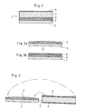
- Fig. 1 is a sectional view in the film width direction of an adhesive-including film according to an embodiment.
- Fig. 2 to Fig. 8C are explanatory diagrams of manufacturing methods therefor.
- This adhesive-including film 1 includes a mold release film 2, a first adhesive layer 3 disposed on this mold release film 2, a second adhesive layer 4 disposed on the first adhesive layer, a base film 5 on the second adhesive layer, and an antireflection film 6 disposed on the film surface opposite to the second adhesive layer 4 of the base film 5.
- the first adhesive layer 3 is highly colored as compared with the second adhesive layer 4.
- the second adhesive layer 4 may be colorless.
- the thickness of the first adhesive layer 3 is varied in the width direction of the film 1.
- the thickness of the central portion of the first adhesive layer 3 in the width direction of the film is larger than the thicknesses of both end sides.
- the total thickness of the first adhesive layer 3 and the second adhesive layer 4 is uniform all over the film.
- the second adhesive layer may not be disposed.
- the film 1 is long-extended in a direction orthogonal to the width direction (direction perpendicular to the drawing in Fig. 1).
- the thickness of the first adhesive layer 3 may be uniform or periodically changed in the longitudinal direction of the film.
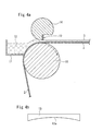
- the mold release film 2 is looped over an application roll 10 and is forwarded continuously.
- the direction of the center of axis of this application roll 10 is set in the horizontal direction.
- a liquid dam 11 is disposed adjacent to this application roll 10, and a coating solution 12 held in the liquid dam 11 is in contact with the film surface of the mold release film 2.
- the coating solution 12 is adhered to the film surface and is pulled up.
- the coating solution 12 pulled up while being adhered to this film 2 is scraped and leveled with a blade 13, so that the first adhesive layer 3 is formed.
- This blade 13 is attached to a comma 14.
- the lower edge of the blade 13 has the form of an arch surface 13a curved to become convex upward in the width direction of the film 2. Consequently, the clearance between the blade 13 and the film 12 reaches a maximum value at the central portion of the width direction of the film 2 and decreases with increasing proximity to both end sides of the film 2. Since the coating solution 12 on the film 2 is leveled with this blade 13, the thickness of the adhesive layer 3 disposed on the film 2 reaches a maximum at the central portion in the width direction of the film 2 and decreases with increasing proximity to both end sides.
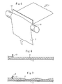
- the second adhesive layer 4 may be formed on the first adhesive layer 3, as shown in Figs. 2A and 2B, and the base film 5 may be stacked thereon.
- the second adhesive layer 4 may be formed on the base film 5, and the mold release film 2 provided with the first adhesive layer 3 and the base film 5 provided with the second adhesive layer 4 may be stacked, as shown in Fig. 3.
- the thickness of the second adhesive layer 4 shown in Fig. 3 decreases with increasing proximity to the central portion in the width direction of the film 5.
- the above-described second adhesive layer 4 may be formed on the film 5 by using a blade curved to become convex downward, for example.
- the first adhesive layer 3 of the film 1 is highly colored as compared with the second adhesive layer 4. Therefore, the film 1 is most highly colored (the total light transmittance is low.) at the central portion in the width direction, and becomes lightly colored with increasing proximity to both end sides. That is, the total light transmittance of the film 1 is increased with increasing proximity to both end sides in the width direction.
- the thickness of the first adhesive layer 3 is made uniform in the longitudinal direction of the film 2.
- the thickness of the first adhesive layer 3 is periodically varied in the longitudinal direction of the film 2.
- an adhesive-including film in which dark and light are periodically varied not only in the width direction of the film 1, but also in the direction orthogonal thereto, is produced.
- the thickness of the first adhesive layer 3 can also be periodically varied in the longitudinal direction of the film 2 by shaking the upper edge side of the blade 13.
- the thickness of the first adhesive layer 3 can also be periodically varied in the longitudinal direction of the film 2 by periodically moving the blade 3 up or down.
- the thickness of the first adhesive layer 3 may also be varied in the longitudinal direction of the film 2 by using a lip die 20 as shown in Fig. 8A.
- the lips 21 of this lip die 20 have a large width of the opening at the center in the width direction, and the width of the opening decreases with increasing proximity to both end sides in the width direction, as shown in Fig. 8B.
- the thickness of the first adhesive layer 3 reaches a maximum at the center in the width direction, and the thickness decreases with increasing proximity to both end sides.
- the thickness distribution of the adhesive layer 3 in the film width direction in the above-described embodiment is an example of aspects of the present invention, and the thickness distribution is not limited to this.
- the thickness of the adhesive layer 3 may also be periodically varied in the film width direction.
- a film exhibiting a percentage a/b x 100% of the total light transmittance a at the center in the film width direction relative to the total light transmittance b on both end sides of about 10% to 95% can be provided.
- the rate of change of the total light transmittance in the longitudinal direction of the film can be made 10% or less.
- a film exhibiting a percentage c/d x 100% of the lowest total light transmittance c at the center in the film width direction relative to the highest total light transmittance d of about 20% to 95% can be provided.
- the materials and thicknesses of the mold release film 2, the adhesive layers 3 and 4, the base film 5, and the antireflection film 6 are not specifically limited.
- the thickness of the mold release film 2 is 25 to 100 ⁇ m
- the total thickness of the first adhesive layer 3 and the second adhesive layer 4 is 20 to 40 ⁇ m
- the thickness of the base film 5 is 30 to 250 ⁇ m
- the thickness of the antireflection film 6 is 0.1 to 10 ⁇ m.
- the thickness of the central portion of the first adhesive layer 3 may be set at about 1.2 to 3 times the thickness of both end sides, although not limited to this.
- the colors of the adhesive layers 3 and 4 are not specifically limited.
- the width of the film 1 is set at, for example, 500 to 1,000 mm, although not limited to this.
- a coloring matter added to the adhesive to adjust the total light transmittance of the adhesive layer is not specifically limited.
- pigments include inorganic pigments, e.g., carbon black, titanium oxide, chromium oxide, oxide yellow, red ion oxide, and ultramarine, and organic pigments, e.g., azo pigments, phthalocyanine pigments, anthracene pigments, threne pigments, and dioxazine pigments, although not limited to them.
- An example of adhesives suitable for use in the film of the present invention is an adhesive containing a (meth)acrylic resin as a primary component and an epoxy compound as a cross-linking agent, wherein the (meth)acrylic resin contains 1 to 25 percent by weight of monomer component having a carboxyl group, as a copolymerization component of the alkyl (meth)acrylate.
- This suitable adhesive is the same as that of the adhesive layer 73 shown in Fig. 10 which will be described below.
- films 2 and 5 examples include cellulose films of triacetyl cellulose base, polycarbonate films, polyester films, e.g., polyethylene terephthalate, and polyolefin films, e.g., polyethylene and polypropylene, although not limited to them.
- the film 1 of the present invention may include at least one of a hard coat layer, an electrically conductive layer, an antireflection layer, an antiglare layer, and the like.
- the adhesive-including film in accordance with the present invention may be manufactured by mixing at least two formulations having different total light transmittances and applying the resulting mixture to a film immediately after the mixing so as to form (a film of) the adhesive layer.
- This method is effective against not only variations in luminance, but also variations in color saturation, since the thickness of the adhesive layer is not varied in a surface and, in addition, toning can be performed on a formulation basis.
- the above-described film formation method can be used.
- the T die method when the supply of material is divided into three before extrusion, and the resulting three components are put in so that the total light transmittances become large-medium-small from the end, a film of the adhesive having a large-medium-small total light transmittance after film formation can be formed.
- a film of the adhesive having a small-large-small total light transmittance after film formation can be formed.
- the total light transmittance and the quantity of supply of each material are controlled and, thereby, an adhesive having a total light transmittance being continuously varied in one desired direction can be produced. Since this method can independently change the toning of each material, an adhesive layer having not only a total light transmittance being continuously varied, but also a color saturation being continuously varied, can be produced.
- the total light transmittance of the adhesive layer is varied and, thereby, the total light transmittance of the film is varied in a one-dimensional direction or a two-dimensional direction.
- the total light transmittance of the film may also be varied in a one-dimensional direction or a two-dimensional direction by varying the total light transmittance of the base film itself.
- the content of coloring matter or pigment in the film is made to have a distribution in the one-dimensional direction or the two-dimensional direction during film formation.
- This coloring matter or pigment may be, for example, the above-described coloring matter or pigment to be contained in the adhesive.
- the concentration of the coloring matter or pigment in the base film may be kept constant, and the total light transmittance of the film may be varied in a one-dimensional direction or a two-dimensional direction by varying the thickness of the base film.
- a colored layer different from the adhesive layer may be disposed on the surface of the base film, and the total light transmittance of the film may be varied in a one-dimensional direction or a two-dimensional direction by varying the thickness or the color strength of this colored layer.
- This colored layer may be disposed only for the purpose of varying the total light transmittance, or may also serves as a functional layer, e.g., an antireflection layer, an antiglare layer, a hard coat layer, or an electrically conductive layer.
- a printing material containing a coloring matter or a pigment is printed. This coloring matter or pigment may be similar to that contained in the above-described adhesive layer.
- a flask was provided with a thermometer, an agitator, a reflux cooling pipe, and a nitrogen introduction pipe, and 68 parts by weight of n-butyl acrylate, 22 parts by weight of methyl acrylate, 10 parts by weight of acrylic acid, 0.1 parts by weight of azobisisobutylonitrile, 40 parts by weight of ethyl acetate, and 60 parts by weight of toluene were put therein. Nitrogen was introduced through the nitrogen introduction pipe and, thereby, the inside of the flask was brought into a nitrogen atmosphere.
- a coating solution was prepared by blending 100 parts by weight of polymer solution A with 0.05 parts by weight of epoxy cross-linking agent (trimethylolpropane triglycidyl ether) and 2 parts by weight of pigment (CAB LX905 Black produced by TOYO INK MFG. CO., LTD.).
- the resulting coating solution was applied to a mold release PET film "DIAFOIL MRF38" (produced by Mitsubishi Polyester Film Corp.) having been subjected to a silicone treatment and having a thickness of 38 ⁇ m in a manner as shown in Figs. 4A and 4B, followed by drying.
- the same coating solution as the above-described coating solution except that no pigment was included was further applied thereon, followed by drying.
- a PET film "OLW” (produced by Teijin DuPont Films Japan Limited) having a thickness of 175 ⁇ m was stuck thereon.
- the thickness of the central portion of the adhesive layer 3 was 20 ⁇ m, and the thicknesses of both end sides of the film were 10 ⁇ m.
- the total thickness of the adhesive layer 3 and the adhesive layer 4 was 25 ⁇ m (constant).
- the mold release PET film was peeled off this film.
- the resulting film was stuck to glass having a thickness of 3 mm, and the total light transmittance was measured.
- the total light transmittance of the film was 50% at the center in the width direction, and was 70% at both end sides.
- a film having a total light transmittance being varied in the film width direction is provided.
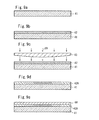
- a colored layer 42 containing a dye which tends to be faded due to ultraviolet light B and has excellent heat resistance (hereafter may be referred to as "an easy-to-fade dye") is formed on a base film 41 (Figs. 9A and 9B).
- this base film 41 examples include cellulose films of triacetyl cellulose base; polycarbonate films; polyester films, e.g., polyethylene terephthalate; and polyolefin films, e.g., polyethylene and polypropylene, although not limited to them.
- the thickness of the base film 41 is controlled at within the range of 25 to 250 ⁇ m since satisfactory strength is attained and the thickness of the dimmer film is not excessively increased.
- the easy-to-fade dye to be blended into the colored layer 42 is not specifically limited.
- “Kayaset Black G” and “Kayaset Black B” produced by Nippon Kayaku Co., Ltd., "Oil Colours”, “Black 141”, and “Oil Colours Black 6” produced by CHUO SYNTHETIC CHEMICAL CO., LTD., and the like can be used.
- the colored layer 42 is an adhesive layer.
- various adhesives of, e.g., rubber base, acryl base, silicone base, and EVA (ethylene-vinyl acetate) base can be used as the adhesive to form the colored adhesive layer.
- the content of the easy-to-fade dye in the colored layer 42 is not specifically limited. However, about 0.1 to 20 percent by weight is preferable. If the content of the easy-to-fade dye in the colored layer 42 is smaller than the above-described range, it is difficult to provide the colored layer with significant changes in color strength by fading through application of the ultraviolet light B. If the content of the easy-to-fade dye is larger than the above-described range, the film formation property and the like of the colored layer is deteriorated.
- the thickness of this colored layer 42 is not specifically limited. However, about 0.01 to 30 ⁇ m is preferable. This is because if the thickness of this colored layer 42 is smaller than the above-described range, it is difficult to provide the colored layer with significant changes in color strength by fading through irradiation of the ultraviolet light B, and if the thickness of the colored layer 42 is larger than the above-described range, the thickness of the dimmer film is increased, and the fading becomes unsatisfactory.
- This colored layer 42 can be formed by applying a predetermined thickness of adhesive composition containing a predetermined quantity of easy-to-fade dye to the base film.
- the coating method is not specifically limited. Examples thereof can include a gravure coater, a bar coater, a roll coater, a knife coater, and a reverse roll coater. Preferably, the gravure coating method is adopted since the uniformity of the thickness is required.
- This colored layer 42 is formed on the base film 41 with a uniform thickness and with uniform color strength.
- the colored layer 42 is irradiated with the ultraviolet light B through a mask 43 having an ultraviolet light B transmission quantity distribution in the surface direction and, thereby, the colored layer 42 is faded so that the color strength is varied in the surface direction (Fig. 9C).
- the mask 43 made of PET film is used.
- the thickness of the central portion of the mask 43 is larger than the thicknesses of both end portions, and the thickness is continuously varied from the central portion toward both end portions.
- the light transmission quantity is continuously decreased from the central portion toward both end portions so that the ultraviolet light B transmission quantity is decreased at the central portion and the ultraviolet light B transmission quantity is increased at both end portions.
- the thickness of this mask 43 is appropriately determined in accordance with the irradiation quantity of light required for fading the colored layer 42.
- the ultraviolet light B (310 nm) transmission quantity of the PET film is about 20% when the thickness is 10 ⁇ m, and is about 4.4% when the thickness is 20 ⁇ m. Consequently, the mask 43 is appropriately designed so that a predetermined light transmission quantity can be attained at a predetermined portion while the thickness is within the range of 5 to 30 ⁇ m.
- the mask 43 shown in Fig. 9C can be produced by, for example, performing extrusion while a blade having an arch surface curved to become convex upward in the width direction is disposed at an extrusion hole in the extrusion of the film.
- the mask 43 can be produced by stacking and integrating very thin films, which are molded beforehand and have different areas, at predetermined portions so that predetermined thicknesses are attained.
- the material for the mask is not limited to PET. It is essential only that the material for the mask has excellent ultraviolet light B resistance and the ultraviolet light B transmission quantity can be controlled. Quartz glass, fluororesins, and other resinous materials may be used.
- the material for the mask is not limited to the material in which the ultraviolet light B transmission quantity is varied by changing the thickness, and may be a material in which the ultraviolet light B transmission quantity is varied by changing the ultraviolet light B absorptive power in the surface direction of the mask.
- the ultraviolet light B (wavelength 280 to 315 nm) can be applied through the above-described mask 43 by using a general ultraviolet light B lamp or metal halide lamp.
- the output of this ultraviolet light B is about 80 to 300 W/cm from the viewpoint of the effect on fading the colored layer 42.
- the degree of fading of the colored layer 42 due to the ultraviolet light B is different depending on the application time of the ultraviolet light B and the distance between the colored layer and the lamp. Therefore, preferably, these conditions, as well as the output, are set appropriately.
- the easy-to-fade dye in the colored layer 42 is faded by applying the ultraviolet light B to the colored layer 42 through the mask 43 and, thereby, the color strength of the colored layer 42 is varied in the surface direction thereof.
- the quantity of application of the ultraviolet light B is small at the central portion of the colored layer 42, and the quantity of application of the ultraviolet light B is large at both end portions.
- the color strength of the colored layer 42A after being faded is continuously varied from the center toward both end portions so that the color strength is high at the central portion and the color strength is low at both end portions (Fig. 9D).
- an adhesive layer 44 containing a pigment is formed on this faded colored layer 42A.
- the adhesive layer may be formed on the surface opposite to the colored layer of the base film.
- pigments include inorganic pigments, e.g., carbon black, titanium oxide, chromium oxide, oxide yellow, red ion oxide, and ultramarine, and organic pigments, e.g., azo pigments, phthalocyanine pigments, anthracene pigments, threne pigments, and dioxazine pigments, although not limited to them.
- the content of the pigment in the adhesive layer 44 is not specifically limited. However, about 0.01 to 10 percent by weight is preferable. If the content of the pigment in the adhesive layer 44 is smaller than the above-described range, the effect on adjusting the transmitted color due to disposition of this adhesive layer 44 cannot be satisfactorily exerted. If the content of the pigment is larger than the above-described range, the film formation property and the like of the adhesive layer is deteriorated and, in addition, satisfactory adhesion cannot be attained.
- the thickness of this adhesive layer 44 is not specifically limited. However, 5 to 50 ⁇ m is preferable. If the thickness of the adhesive layer 44 is smaller than the above-described range, the effect on adjusting the transmitted color due to disposition of this adhesive layer 44 cannot be adequately exerted. If the thickness of the adhesive layer 44 is larger than the above-described range, the thickness of the dimmer film is increased, and the productivity is deteriorated.
- This adhesive layer 44 can be formed by applying a predetermined thickness of adhesive composition containing a predetermined quantity of pigment on the colored layer 42 or on the side opposite thereto.
- the coating method therefor is not specifically limited. Although a method similar to the coating method for the colored layer 42 can be adopted, a knife coater method is preferable since the viscosity of the coating solution is high.
- this adhesive layer 44 is formed on the colored layer 42 with a uniform thickness and with uniform color strength as well.
- a mold release film is stuck to this adhesive layer 44.
- the material for this mold release film is similar to that for the above-described base film 41, and the thickness thereof is usually about 25 to 100 ⁇ m.
- the thus produced dimmer film is most highly colored (the total light transmittance is low.) at the central portion, and becomes lightly colored with increasing proximity to both end sides. That is, the total light transmittance of the dimmer film is increased with increasing proximity to both end sides.
- the dimmer film is basically composed of the base film 41, the faded colored layer 42A, preferably faded colored adhesive layer, and the adhesive layer 44, as shown in Fig. 9E.
- the mold release film may be disposed on the adhesive layer 44, as described above.
- An antireflection layer may be disposed on the surface opposite to the surface provided with the colored layer of the base film. In this case, preferably, the thickness of the antireflection layer is about 0.1 to 10 ⁇ m.
- the antireflection layer may be formed before the colored layer is formed.
- a hard coat layer, an electrically conductive layer, an antiglare layer, and the like may be included.
- the colored layer may also serve as these functional layers.
- a film exhibiting a percentage a/b x 100% of the total light transmittance a at the center relative to the total light transmittance b on both end sides of about 10% to 95% can be provided.
- the total light transmittance of this dimmer film may be varied one-dimensionally or two-dimensionally in the film surface direction.
- the design of the total light transmittance of the dimmer film can be arbitrarily changed by selecting the mask.
- the colored layer disposed on the base film and containing the easy-to-fade dye is irradiated with the ultraviolet light B having a light quantity distribution in the surface direction so that the colored layer is faded and the color strength is varied in the surface direction.
- the adhesive layer containing the pigment is disposed and, thereby, the transmitted color of the faded colored layer is adjusted.
- the method for manufacturing the dimmer film is not limited to the method shown in Figs. 9A to 9E.
- the colored layer 42 containing the easy-to-fade dye is formed on the base film 41, the ultraviolet light B is applied through the mask 43 and, thereafter, the adhesive layer containing the pigment and disposed on the mold release film is stuck thereto, so that the dimmer film can be produced as well.
- An example of adhesives suitable for use in the dimmer film of the present invention is an adhesive containing a (meth)acrylic resin as a primary component and an epoxy compound as a cross-linking agent, wherein the (meth)acrylic resin contains 1 to 25 percent by weight of monomer component having a carboxyl group, as a copolymerization component of the alkyl (meth)acrylate.
- This adhesive is the same as the adhesive used in the adhesive layer 73 which will be described below with reference to Fig. 10.
- the dimmer film of the present invention and the manufacturing method therefor will be more specifically described below with reference to examples and comparative examples.
- the present invention is not limited to the following examples, and covers various modifications and the like included within the scope of the present invention.
- a dimmer film was produced by the method shown in Figs. 9A to 9E.
- a colored adhesive layer (thickness 8 ⁇ m) made of an acrylic adhesive ("Foret M-80" produced by Soken Chemical and Engineering Co., Ltd.) containing 5 percent by weight of an easy-to-fade dye, "Kayaset Black G” produced by Nippon Kayaku Co., Ltd., was formed by a gravure coating method on the surface of "0300" (thickness 100 ⁇ m) produced by Mitsubishi Polyester Film Corp., serving as the base film.
- This colored adhesive layer is irradiated with the ultraviolet light B (output 80 W/cm) from a UV-B lamp "TL/12 lamp” produced by Philips Japan Ltd., at a distance of 40 cm for 60 minutes through the following mask and, thereby, the colored adhesive layer was faded.
- an adhesive layer (thickness 25 ⁇ m) was formed on the faded colored adhesive layer by using an acrylic adhesive ("2065M” produced by Soken Chemical and Engineering Co., Ltd.) containing 0.1 percent by weight of "CAB LX905" and 0.4 percent by weight of "CAB LX716", each produced by TOYO INK MFG. CO., LTD., as a pigment.
- the total light transmittance and the transmitted color of the thus produced dimmer film are shown in Table 1. A desired transmitted color was attained.
- a colored adhesive layer and an adhesive layer were formed as in Example 1 except that the ultraviolet light B was not applied.
- the total light transmittance and the transmitted color of the resulting film are shown in Table 1.
- Example 2 A dimmer film was formed as in Example 1 except that the adhesive layer was not formed.
- the total light transmittance of the resulting film is shown in Table 1.
- the transmitted color was yellow and, therefore, any desired transmitted color was not attained.
- Total light transmittance Transmitted color Example 2 central portion: 67%, both end portions: 85%, varying continuously gray, desired transmitted color Comparative example 1 65%, uniform 65%, uniform gray gray Comparative example 2 central portion: 70%, both end portions: 91%, varying continuously central portion: gray, both end portions: yellow, undesired transmitted color
- the dimmer film of the present invention can be effectively applied to liquid crystal displays of back light system or front light system, other displays, e.g., CRT, PDP, and FED, and in addition, display panels, e.g., electric bulletin boards, having light sources.
- other displays e.g., CRT, PDP, and FED
- display panels e.g., electric bulletin boards, having light sources.
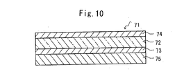
- Fig. 10 is a sectional view showing an embodiment of a display functional film according to the present invention.
- an adhesive layer 73 made of the adhesive according to the present invention is disposed on one surface of a base film 72, a functional layer 74, e.g., a hard coat layer, an electrically conductive layer, an antiglare layer, or an antireflection layer, is disposed on the other surface, and a mold release film 75 is disposed on the adhesive layer 73.
- a functional layer 74 e.g., a hard coat layer, an electrically conductive layer, an antiglare layer, or an antireflection layer
- the display adhesive of the present invention used for the above-described display functional film 71 of the present invention will be described below.
- the display adhesive of the present invention contains a (meth)acrylic resin as a primary component and an epoxy compound as a cross-linking agent, wherein the (meth)acrylic resin contains 1 to 25 percent by weight of monomer component having a carboxyl group, as a copolymerization component of the alkyl (meth)acrylate.
- alkyl (meth)acrylates constituting the (meth)acrylic resin according to the present invention include alkyl esters of acrylic acid or methacrylic acid having an alkyl group, e.g., a methyl group, an ethyl group, an isopropyl group, a n-butyl group, an isobutyl group, an isoamyl group, a hexyl group, a heptyl group, a cyclohexyl group, a 2-ethylhexyl group, an isooctyl group, an isononyl group, a lauryl group, a dodecyl group, an isomyristyl group, and an octadecyl group. These may be used alone or in combination.
- Examples of monomer components having a carboxyl group include (meth)acrylic acid; carboxyalkyl (meth)acrylates, e.g., carboxyethyl (meth)acrylate and carboxypentyl (meth)acrylate; itaconic acid; maleic acid; and crotonic acid. These may be used alone or in combination.
- the (meth)acrylic resin may contain other copolymerization components in addition to the above-described alkyl (meth)acrylate and a monomer component having a carboxyl group.
- other usable copolymerization components include maleimide monomers, e.g., N-cyclohexylmaleimide, N-isopropylmaleimide, N-laurylmaleimide, and N-phenylmaleimide; itaconimide monomers, e.g., N-methylitaconimide, N-ethylitaconimide, N-butylitaconimide, N-octylitaconimide, N-2-ethylhexylitaconimide, N-cyclohexylitaconimide, and N-laurylitaconimide; succinimide monomers, e.g., N-(meth)acryloyloxymethylenesuccinimide, N-(meth)acryloyl-6
- Monomer components having a functional group other than the carboxylic group can also be used.
- monomers having a functional group include hydroxyl-containing monomers, e.g., 2-hydroxyethyl (meth)acrylate, 2-hydroxypropyl (meth)acrylate, 4-hydroxybutyl (meth)acrylate, 6-hydroxyhexyl (meth)acrylate, 8-hydroxyoctyl (meth)acrylate, 10-hydroxydecyl (meth)acrylate, 12-hydroxylauryl (meth)acrylate, and (4-hydroxymethylcyclohexyl)-methyl acrylate; epoxy-containing monomers, e.g., glycidyl (meth)acrylate; and amide monomers, e.g., (meth)acrylamide, N-acryloylmorpholine, N-substituted (meth)acrylamide, and N-vinylpyrrolidone.
- hydroxyl-containing monomers e.g., 2-hydroxyethyl (
- the content of monomer component containing a carboxyl group in the (meth)acrylic resin is smaller than 1 percent by weight, the adhesion to a display panel made of, e.g., glass, is lowered. If the content exceeds 25 percent by weight, the glass transition temperature Tg of the adhesive tends to be increased, so that satisfactory tackiness cannot be attained. Therefore, it is preferable that the content of monomer component containing a carboxyl group is 1 to 25 percent by weight, in particular, 5 to 20 percent by weight.
- the content of alkyl (meth)acrylate which is a primary component of the (meth)acrylic resin is 50 percent by weight or more, in particular, 60 percent by weight or more in order to ensure the optical properties as the (meth)acrylic resin.
- the (meth)acrylic resin according to the present invention is produced from an alkyl (meth)acrylate, a monomer component having a carboxyl group, and other copolymerization components used as required by polymerizing these monomer components through a common polymerization system, e.g., solution polymerization, emulsion polymerization, bulk polymerization, or suspension polymerization.
- a thermal polymerization initiator or a photopolymerization initiator is used.
- potassium persulfate, ammonium persulfate, hydrogen peroxide, a redox initiator in which the above-described compound and a reducing agent are used in combination, or the like is used.
- thermal polymerization initiators include organic peroxides, e.g., benzoyl peroxide, t-butyl perbenzoate, cumene hydroperoxide, diisopropyl peroxydicarbonate, di-n-propyl peroxydicarbonate, di(2-ethoxyethyl) peroxydicarbonate, t-butyl peroxyneodecanoate, t-butyl peroxypivalate, (3,5,5-trimethylhexanoyl) peroxide, dipropionyl peroxide, and diacetyl peroxide; and azo compounds, e.g., 2,2'-azobisisobutylonitrile, 2,2'-azobis(2-methylbutylonitrile), 1,1'-azobis(cyclohexane-1-carbonitrile), 2,2'-azobis(2,4-dimethylvaleronitrile), 2,2'-azobis(2,4-di)
- photopolymerization initiators include acetophenone initiators, e.g., 4-(2-hydroxyethoxy)phenyl(2-hydroxy-2-propyl) ketone, ⁇ -hydroxy- ⁇ , ⁇ '-dimethylacetophenone, methoxyacetophenone, 2,2-dimethoxy-2-phenylacetophenone, 1-hydroxycyclohexylphenyl ketone, and 2-methyl-1-[4-(methylthio)-phenyl]-2-morpholinopropane-1; benzoin ether initiators, e.g., benzoyl ethyl ether and benzoin isopropyl ether; ketal initiators, e.g., benzyl methyl ketal; benzophenone initiators, e.g., benzophenone, benzoylbenzoic acid, and 3,3'-dimethyl-4-methoxybenzophenone; and thioxanthone initiators, e.g., thio
- the usage of the polymerization initiator is not specifically limited. However, preferably, the usage is usually 0.001 to 5 percent by weight relative to the monomer component to be used.
- the weight average molecular weight of the (meth)acrylic resin is 500,000 to 2,000,000. If the weight average molecular weight of the (meth)acrylic resin is smaller than 500,000, the heat resistance to 120°C or more is deteriorated. If the weight average molecular weight exceeds 2,000,000, the synthesis takes significantly much time and, in addition, the viscosity of the adhesive solution becomes very high, so that the productivity, e.g., the workability of coating, is deteriorated.
- the cross-linking agent contained in the adhesive is an epoxy compound.
- the epoxy cross-linking agent may be ethylene glycol diglycidyl ether, propylene glycol diglycidyl ether, diglycidyl ether, trimethylolpropane triglycidyl ether, or the like. These may be used alone or in combination.
- the content of the epoxy cross-linking agent is too small, the effect on improving the adhesion due to compounding the epoxy cross-linking agent is not satisfactorily exerted. If the content is too large, significant shrinkage is effected by cross-linking and, thereby, the film may be warped. Therefore, it is preferable that the content is 0.5 to 50 percent by weight relative to the monomer component having a carboxyl group in the (meth)acrylic resin.
- Cross-linking agents other than the epoxy cross-linking agent may be contained.
- the above-described cross-linking agents include multifunctional isocyanate cross-linking agents, e.g., tolylene diisocyanate, trimethylolpropane tolylene diisocyanate, and diphenylmethane tolylene diisocyanate; melamine resin cross-linking agents; metal salt cross-linking agents; metal chelate cross-linking agents, and amino resin cross-linking agents.
- the total content of the above-described epoxy cross-linking agent and the cross-linking agents other than the epoxy cross-linking agent is 10 percent by weight or less relative to the (meth)acrylic resin.
- the hue, the lightness, and the color saturation of the light from the display are adjusted by functional light transmission films.
- adhesive layers are provided with this adjustment function. Therefore, a dye or pigment can be added to the adhesive of the present invention in order to provide such a function.
- the pigment is used preferably as compared with the dye from the viewpoint of the durability.
- Examples of pigments having excellent compatibility with the adhesive of the present invention include CAB pigments produced by TOYO INK MFG. CO., LTD. It is possible to perform desired toning by using them alone or in combination.
- the adhesive of the present invention may be blended with additives, e.g., ultraviolet absorbers, conductivity-imparting agents, oxidation inhibitors, antioxidants, natural and synthetic resins, glass fibers, and glass beads within the range in which the transparency is not impaired. Fine particles may be blended to provide the adhesive with the light diffusion property.
- additives e.g., ultraviolet absorbers, conductivity-imparting agents, oxidation inhibitors, antioxidants, natural and synthetic resins, glass fibers, and glass beads within the range in which the transparency is not impaired. Fine particles may be blended to provide the adhesive with the light diffusion property.
- a (meth)acrylic resin as a primary component of the adhesive may be dissolved or dispersed in an appropriate organic solvent, e.g., toluene and ethyl acetate, so as to prepare a solution containing about 10 to 40 percent by weight of adhesive, an epoxy cross-linking agent may be further added thereto, followed by agitating. Thereafter, the resulting solution may be applied by a flow casting method or a coating method to one surface of the base film 72, followed by drying. Alternatively, the above-described solution containing the adhesive may be applied to a separator (mold release film 75), and be dried so as to form the adhesive layer 73. Subsequently, this may be stuck to the base film 72.
- an appropriate organic solvent e.g., toluene and ethyl acetate
- the thickness of the adhesive layer 73 disposed in the display functional film 71 is not specifically limited. However, in general, it is preferable that the adhesive layer 73 is formed to have a thickness of about 5 to 50 ⁇ m.
- the base film 72 of the display functional film 71 is not specifically limited. However, a base film having optical transparency is used preferably.
- Examples of preferable films used as the base film include cellulose films made of, e.g., triacetyl cellulose; polycarbonate films; polyester films made of, e.g., polyethylene terephthalate (PET); and polyolefin films made of, e.g., polyethylene and polypropylene, from the viewpoint of optical properties, strength, economy, and the like.
- the thickness thereof is about 30 to 300 ⁇ m from the viewpoint of the strength, reduction in thickness, and the like.
- Examples of functional layers 74 to be disposed on the base film 72 include at least one of a hard coat layer, a transparent electrically conductive layer, an antiglare layer, an antireflection layer, and the like, although not limited to them.
- a hard sheet e.g., a glass sheet, an acrylic sheet, or a polycarbonate sheet, having a thickness of about 1 to 10 mm is used as a display panel to which the display functional film is stuck.
- the material and the thickness are not specifically limited.
- a flask was provided with a thermometer, an agitator, a reflux cooling pipe, and a nitrogen introduction pipe, and 68 parts by weight of n-butyl acrylate, 22 parts by weight of methyl acrylate, 10 parts by weight of acrylic acid, 0.1 parts by weight of azobisisobutylonitrile, 40 parts by weight of ethyl acetate, and 60 parts by weight of toluene were put therein. Nitrogen was introduced through the nitrogen introduction pipe and, thereby, the inside of the flask was brought into a nitrogen atmosphere.
- a coating solution was prepared by blending 100 parts by weight of polymer solution A with 0.05 parts by weight of epoxy cross-linking agent (trimethylolpropane triglycidyl ether). The resulting coating solution was applied to a mold release PET film "DIAFOIL MRF38” (produced by Mitsubishi Polyester Film Corp.) having been subjected to a silicone treatment and having a thickness of 38 ⁇ m, followed by drying.
- a PET film “OLW” (produced by Teijin DuPont Films Japan Limited) having a thickness of 175 ⁇ m was stuck thereto.
- the mold release PET film was peeled off this film.
- the resulting film was stuck to glass having a thickness of 3 mm to prepare a measurement sample.
- the adhesion and the degree of discoloration were evaluated by the following methods. The results are shown in Table 2.
- the polymerization reaction was performed as in Example 3 except that 65 parts by weight of n-butyl acrylate, 20 parts by weight of methyl acrylate, 15 parts by weight of acrylic acid-2-hydroxyethyl ester, 0.1 parts by weight of azobisisobutylonitrile, 40 parts by weight of ethyl acetate, and 60 parts by weight of toluene were put in the flask, so that an acrylic polymer solution having a weight average molecular weight of about 750,000 and Tg of about -23°C was produced. Ethyl acetate was added to the acrylic polymer solution so that the solids content became 28 percent by weight and, therefore, a polymer solution B was produced.
- Example 3 An adhesive layer was formed as in Example 3 except that 0.1 parts by weight of tolylene diisocyanate was added to 100 parts by weight of this polymer solution B.
- the adhesion and the degree of discoloration were evaluated as in the above description. The results are shown in Table 2.
- the adhesive of the present invention has high adhesion, and the adhesion and the optical properties exhibit excellent high-temperature durability and high-humidity durability.
- the display adhesive of the present invention has high adhesion to a display panel and the adhesion and the optical properties exhibit excellent high-temperature durability and high-humidity durability. Consequently, the display functional film of the present invention provided with the adhesive layer made of the display adhesive of the present invention can stably maintain excellent adhesion and transparency for the long term without occurrence of deterioration, e.g., peeling and yellowing, in the use for various electronic display panels.
Landscapes
- Chemical & Material Sciences (AREA)
- Physics & Mathematics (AREA)
- Organic Chemistry (AREA)
- General Physics & Mathematics (AREA)
- Optics & Photonics (AREA)
- Manufacturing & Machinery (AREA)
- Engineering & Computer Science (AREA)
- Health & Medical Sciences (AREA)
- Polymers & Plastics (AREA)
- Medicinal Chemistry (AREA)
- Chemical Kinetics & Catalysis (AREA)
- Materials Engineering (AREA)
- Adhesive Tapes (AREA)
- Laminated Bodies (AREA)
- Adhesives Or Adhesive Processes (AREA)
- Optical Elements Other Than Lenses (AREA)
- Application Of Or Painting With Fluid Materials (AREA)
Applications Claiming Priority (9)
| Application Number | Priority Date | Filing Date | Title |
|---|---|---|---|
| JP2002303351 | 2002-10-17 | ||
| JP2002303350 | 2002-10-17 | ||
| JP2002303351 | 2002-10-17 | ||
| JP2002303350 | 2002-10-17 | ||
| JP2003004721 | 2003-01-10 | ||
| JP2003004721 | 2003-01-10 | ||
| JP2003311574 | 2003-09-03 | ||
| JP2003311574 | 2003-09-03 | ||
| PCT/JP2003/012876 WO2004035665A1 (fr) | 2002-10-17 | 2003-10-08 | Film et adhesif autocollant utilise avec |
Publications (3)
| Publication Number | Publication Date |
|---|---|
| EP1564239A1 true EP1564239A1 (fr) | 2005-08-17 |
| EP1564239A4 EP1564239A4 (fr) | 2007-08-01 |
| EP1564239B1 EP1564239B1 (fr) | 2010-12-08 |
Family
ID=32110953
Family Applications (1)
| Application Number | Title | Priority Date | Filing Date |
|---|---|---|---|
| EP03751377A Expired - Lifetime EP1564239B1 (fr) | 2002-10-17 | 2003-10-08 | Procede pour preparer un film avec adhesif autocollant |
Country Status (7)
| Country | Link |
|---|---|
| US (1) | US20050191485A1 (fr) |
| EP (1) | EP1564239B1 (fr) |
| JP (1) | JPWO2004035665A1 (fr) |
| KR (1) | KR20050073558A (fr) |
| AU (1) | AU2003271124A1 (fr) |
| DE (1) | DE60335285D1 (fr) |
| WO (1) | WO2004035665A1 (fr) |
Cited By (5)
| Publication number | Priority date | Publication date | Assignee | Title |
|---|---|---|---|---|
| WO2006094079A3 (fr) * | 2005-03-03 | 2006-11-09 | 3M Innovative Properties Co | Ruban adhesif thermodurcissable, articles et procedes associes |
| EP1986040A1 (fr) * | 2007-04-25 | 2008-10-29 | Samsung Electronics Co., Ltd. | Adhésif, ensemble de polarisateur et dispositif d'affichage |
| CN103481564A (zh) * | 2013-08-16 | 2014-01-01 | 武汉羿阳科技有限公司 | 一种自动调节透光率的窗膜 |
| WO2018115556A1 (fr) * | 2016-12-22 | 2018-06-28 | Alba Armendariz Alvarez | Ruban flexible et rouleau pour enrouler ou dérouler des bobines de matériau laminé recouvert par ledit ruban |
| CN112592675A (zh) * | 2020-11-26 | 2021-04-02 | 江苏双星彩塑新材料股份有限公司 | 一种随角异色窗膜 |
Families Citing this family (24)
| Publication number | Priority date | Publication date | Assignee | Title |
|---|---|---|---|---|
| JP2006027251A (ja) * | 2004-07-20 | 2006-02-02 | Kenichi Shu | 画面から硝子に用いる多層式フイルム |
| JP2006088016A (ja) * | 2004-09-22 | 2006-04-06 | Bridgestone Corp | 導電性ローラの製造方法およびこの方法により製造された導電性ローラ |
| JP2006088015A (ja) * | 2004-09-22 | 2006-04-06 | Bridgestone Corp | 導電性ローラの製造方法およびこの方法により製造された導電性ローラ |
| JP2006088681A (ja) * | 2004-09-24 | 2006-04-06 | Kenichi Shu | 画面に用いるフイルム |
| JP2007041382A (ja) * | 2005-08-04 | 2007-02-15 | Hitachi Cable Ltd | 光ファイバケーブル |
| JP5382841B2 (ja) * | 2005-10-31 | 2014-01-08 | 日東電工株式会社 | 導電性積層フィルム、タッチパネル用電極板、タッチパネルおよび導電性積層フィルム用粘着剤 |
| WO2007066524A1 (fr) | 2005-12-06 | 2007-06-14 | Konica Minolta Opto, Inc. | Procede de production, appareil de transfert, film fonctionnel possedant une couche de revetement dur et film fonctionnel possedant un couche antireflet |
| KR101040963B1 (ko) * | 2007-06-04 | 2011-06-16 | 주식회사 엘지화학 | 태양전지용 점착제 조성물 |
| JP5541707B2 (ja) * | 2009-08-19 | 2014-07-09 | キヤノン株式会社 | 表示モジュール |
| JP5757288B2 (ja) * | 2010-05-26 | 2015-07-29 | 旭硝子株式会社 | 粘着層付き透明面材、表示装置およびそれらの製造方法 |
| CN103249552B (zh) | 2010-12-08 | 2015-04-08 | 旭硝子株式会社 | 带粘合层的透明面材、显示装置及它们的制造方法 |
| JP5757291B2 (ja) * | 2010-12-08 | 2015-07-29 | 旭硝子株式会社 | 粘着層付き透明面材の製造方法 |
| GB2539794B (en) * | 2013-12-17 | 2020-10-21 | Halliburton Energy Services Inc | Drilling modeling calibration, including estimation of drill string stretch and twist |
| CN107229091B (zh) * | 2016-03-24 | 2020-10-13 | 深超光电(深圳)有限公司 | 偏光片、显示面板及显示器 |
| JP7275471B2 (ja) * | 2017-10-02 | 2023-05-18 | Agc株式会社 | 透明基体および表示装置 |
| JP7167561B2 (ja) * | 2018-09-04 | 2022-11-09 | 大日本印刷株式会社 | 転写用ハードコートフィルム積層体、及び、その製造方法 |
| JP6906560B2 (ja) * | 2019-04-03 | 2021-07-21 | リンテック株式会社 | 粘着シートおよび表示体 |
| JP7526020B2 (ja) * | 2020-03-31 | 2024-07-31 | 日東電工株式会社 | 光学積層体 |
| JP7387522B2 (ja) * | 2020-03-31 | 2023-11-28 | 日東電工株式会社 | 光学積層体 |
| JP7338085B2 (ja) * | 2020-03-31 | 2023-09-04 | 日東電工株式会社 | 光学積層体 |
| CN111732908B (zh) * | 2020-07-31 | 2024-06-14 | 常州斯威克新材料科技有限公司 | 一种一体化的光伏组件封装胶膜 |
| CN112708367B (zh) * | 2020-12-22 | 2022-11-15 | 凯鑫森(上海)功能性薄膜产业股份有限公司 | 一种耐刮防眩变色贴膜及其制备方法 |
| CN116745114A (zh) * | 2020-12-24 | 2023-09-12 | Agc株式会社 | 带有防眩膜的透明基体及其制造方法 |
| EP4596510A1 (fr) * | 2022-09-28 | 2025-08-06 | Sekisui Chemical Co., Ltd. | Corps de modulation de lumière, verre feuilleté et automobile |
Family Cites Families (7)
| Publication number | Priority date | Publication date | Assignee | Title |
|---|---|---|---|---|
| US3914016A (en) * | 1973-04-09 | 1975-10-21 | Minnesota Mining & Mfg | Production of gradient density liquid crystal filter |
| JPH11283531A (ja) * | 1998-03-30 | 1999-10-15 | Nippon Electric Glass Co Ltd | 陰極線管 |
| JPH11307017A (ja) * | 1998-04-20 | 1999-11-05 | Nippon Electric Glass Co Ltd | 陰極線管及びその製造方法 |
| JP2001033782A (ja) * | 1999-07-16 | 2001-02-09 | Advanced Display Inc | 液晶表示装置 |
| EP1277570A1 (fr) * | 2000-03-22 | 2003-01-22 | Asahi Glass Company Ltd. | Film stratifie fonctionnel, son procede de production et ecran cathodique sur lequel est colle ledit film |
| JP2002107507A (ja) * | 2000-09-28 | 2002-04-10 | Tomoegawa Paper Co Ltd | 電子ディスプレイ用粘着剤付フィルム |
| JP5145515B2 (ja) * | 2001-02-19 | 2013-02-20 | 綜研化学株式会社 | 光学部材用アクリル系粘着剤組成物及び該組成物を用いた光学部材用粘着シートの製造方法 |
-
2003
- 2003-10-08 KR KR1020057006356A patent/KR20050073558A/ko not_active Ceased
- 2003-10-08 WO PCT/JP2003/012876 patent/WO2004035665A1/fr not_active Ceased
- 2003-10-08 DE DE60335285T patent/DE60335285D1/de not_active Expired - Lifetime
- 2003-10-08 AU AU2003271124A patent/AU2003271124A1/en not_active Abandoned
- 2003-10-08 EP EP03751377A patent/EP1564239B1/fr not_active Expired - Lifetime
- 2003-10-08 JP JP2005501344A patent/JPWO2004035665A1/ja active Pending
-
2005
- 2005-04-11 US US11/102,778 patent/US20050191485A1/en not_active Abandoned
Cited By (11)
| Publication number | Priority date | Publication date | Assignee | Title |
|---|---|---|---|---|
| WO2006094079A3 (fr) * | 2005-03-03 | 2006-11-09 | 3M Innovative Properties Co | Ruban adhesif thermodurcissable, articles et procedes associes |
| US20090004423A1 (en) * | 2005-03-03 | 2009-01-01 | 3M Innovative Properties Company | Thermosettable Adhesive Tape, Articles And Methods |
| US8535473B2 (en) * | 2005-03-03 | 2013-09-17 | 3M Innovative Properties Company | Thermosettable adhesive tape, articles and methods |
| US10184070B2 (en) | 2005-03-03 | 2019-01-22 | 3M Innovative Properties Company | Thermosettable adhesive tape, articles and methods |
| US12479200B2 (en) | 2005-03-03 | 2025-11-25 | 3M Innovative Properties Company | Thermosettable adhesive taped articles |
| EP1986040A1 (fr) * | 2007-04-25 | 2008-10-29 | Samsung Electronics Co., Ltd. | Adhésif, ensemble de polarisateur et dispositif d'affichage |
| CN103481564A (zh) * | 2013-08-16 | 2014-01-01 | 武汉羿阳科技有限公司 | 一种自动调节透光率的窗膜 |
| CN103481564B (zh) * | 2013-08-16 | 2016-04-13 | 武汉羿阳科技有限公司 | 一种自动调节透光率的窗膜 |
| WO2018115556A1 (fr) * | 2016-12-22 | 2018-06-28 | Alba Armendariz Alvarez | Ruban flexible et rouleau pour enrouler ou dérouler des bobines de matériau laminé recouvert par ledit ruban |
| CN112592675A (zh) * | 2020-11-26 | 2021-04-02 | 江苏双星彩塑新材料股份有限公司 | 一种随角异色窗膜 |
| CN112592675B (zh) * | 2020-11-26 | 2022-01-11 | 江苏双星彩塑新材料股份有限公司 | 一种随角异色窗膜 |
Also Published As
| Publication number | Publication date |
|---|---|
| JPWO2004035665A1 (ja) | 2006-02-16 |
| WO2004035665A1 (fr) | 2004-04-29 |
| US20050191485A1 (en) | 2005-09-01 |
| AU2003271124A1 (en) | 2004-05-04 |
| KR20050073558A (ko) | 2005-07-14 |
| EP1564239B1 (fr) | 2010-12-08 |
| EP1564239A4 (fr) | 2007-08-01 |
| DE60335285D1 (de) | 2011-01-20 |
Similar Documents
| Publication | Publication Date | Title |
|---|---|---|
| EP1564239A1 (fr) | Film et adhesif autocollant utilise avec | |
| JP7208435B1 (ja) | 光半導体素子封止用シート | |
| KR102813224B1 (ko) | 점착 시트 | |
| TWI387627B (zh) | 遮光性壓感貼片 | |
| KR20170034321A (ko) | 점착 시트 | |
| WO2017033741A1 (fr) | Couche adhésive pour éléments optiques, élément optique pourvu d'une couche adhésive, et dispositif d'affichage d'images | |
| TWI814994B (zh) | 黏著劑層及黏著片材 | |
| WO2015068571A1 (fr) | Feuille adhesive double face pour fixer des elements de dispositif electronique portatif, et procede de production de dispositifs electroniques portatifs | |
| US20130101842A1 (en) | Pressure-sensitive adhesive tape | |
| KR20170059005A (ko) | 흑연 시트용 점착 시트 | |
| CN107573859A (zh) | 粘合片 | |
| KR20130043589A (ko) | 양면 접착 테이프 | |
| KR20170076584A (ko) | 그래파이트 시트용 점착 시트 | |
| WO2022044364A1 (fr) | Feuille adhésive, dispositif d'affichage et stratifié | |
| WO2021200293A1 (fr) | Composition adhésive transmettant la lumière infrarouge | |
| CN116423948A (zh) | 光半导体元件密封用片 | |
| JP5518356B2 (ja) | 水分散型粘着剤組成物、その製造方法および粘着シート | |
| US12410343B2 (en) | Pressure-sensitive adhesive sheet | |
| US20230132305A1 (en) | Pressure-sensitive adhesive sheet | |
| US20230132107A1 (en) | Pressure-sensitive adhesive sheet | |
| US20230087412A1 (en) | Pressure-sensitive adhesive sheet and pressure-sensitive adhesive composition | |
| JP7436191B2 (ja) | 粘着シート | |
| JP7650716B2 (ja) | 粘着剤組成物、光硬化性粘着剤層、及び光硬化性粘着シート | |
| US20230212434A1 (en) | Pressure-sensitive adhesive sheet | |
| US20230077929A1 (en) | Pressure-sensitive adhesive sheet |
Legal Events
| Date | Code | Title | Description |
|---|---|---|---|
| PUAI | Public reference made under article 153(3) epc to a published international application that has entered the european phase |
Free format text: ORIGINAL CODE: 0009012 |
|
| 17P | Request for examination filed |
Effective date: 20050412 |
|
| AK | Designated contracting states |
Kind code of ref document: A1 Designated state(s): AT BE BG CH CY CZ DE DK EE ES FI FR GB GR HU IE IT LI LU MC NL PT RO SE SI SK TR |
|
| AX | Request for extension of the european patent |
Extension state: AL LT LV MK |
|
| DAX | Request for extension of the european patent (deleted) | ||
| RBV | Designated contracting states (corrected) |
Designated state(s): DE FR GB |
|
| A4 | Supplementary search report drawn up and despatched |
Effective date: 20070628 |
|
| RIC1 | Information provided on ipc code assigned before grant |
Ipc: C08L 101/00 20060101ALI20070622BHEP Ipc: C09J 133/06 20060101ALI20070622BHEP Ipc: B32B 7/02 20060101ALI20070622BHEP Ipc: B32B 5/14 20060101ALI20070622BHEP Ipc: G09F 9/00 20060101ALI20070622BHEP Ipc: G02B 1/10 20060101ALI20070622BHEP Ipc: G02B 5/00 20060101ALI20070622BHEP Ipc: C08J 5/18 20060101AFI20040504BHEP |
|
| 17Q | First examination report despatched |
Effective date: 20090327 |
|
| GRAP | Despatch of communication of intention to grant a patent |
Free format text: ORIGINAL CODE: EPIDOSNIGR1 |
|
| RTI1 | Title (correction) |
Free format text: PROCESS FOR PREPARING A FILM WITH PRESSURE-SENSITIVE ADHESIVE |
|
| RBV | Designated contracting states (corrected) |
Designated state(s): DE GB NL |
|
| GRAJ | Information related to disapproval of communication of intention to grant by the applicant or resumption of examination proceedings by the epo deleted |
Free format text: ORIGINAL CODE: EPIDOSDIGR1 |
|
| GRAP | Despatch of communication of intention to grant a patent |
Free format text: ORIGINAL CODE: EPIDOSNIGR1 |
|
| GRAS | Grant fee paid |
Free format text: ORIGINAL CODE: EPIDOSNIGR3 |
|
| GRAA | (expected) grant |
Free format text: ORIGINAL CODE: 0009210 |
|
| AK | Designated contracting states |
Kind code of ref document: B1 Designated state(s): DE GB NL |
|
| REG | Reference to a national code |
Ref country code: GB Ref legal event code: FG4D |
|
| REF | Corresponds to: |
Ref document number: 60335285 Country of ref document: DE Date of ref document: 20110120 Kind code of ref document: P |
|
| REG | Reference to a national code |
Ref country code: NL Ref legal event code: T3 |
|
| PLBE | No opposition filed within time limit |
Free format text: ORIGINAL CODE: 0009261 |
|
| STAA | Information on the status of an ep patent application or granted ep patent |
Free format text: STATUS: NO OPPOSITION FILED WITHIN TIME LIMIT |
|
| 26N | No opposition filed |
Effective date: 20110909 |
|
| REG | Reference to a national code |
Ref country code: DE Ref legal event code: R097 Ref document number: 60335285 Country of ref document: DE Effective date: 20110909 |
|
| REG | Reference to a national code |
Ref country code: NL Ref legal event code: V1 Effective date: 20120501 |
|
| GBPC | Gb: european patent ceased through non-payment of renewal fee |
Effective date: 20111008 |
|
| PG25 | Lapsed in a contracting state [announced via postgrant information from national office to epo] |
Ref country code: DE Free format text: LAPSE BECAUSE OF NON-PAYMENT OF DUE FEES Effective date: 20120501 Ref country code: NL Free format text: LAPSE BECAUSE OF NON-PAYMENT OF DUE FEES Effective date: 20120501 |
|
| REG | Reference to a national code |
Ref country code: DE Ref legal event code: R119 Ref document number: 60335285 Country of ref document: DE Effective date: 20120501 |
|
| PG25 | Lapsed in a contracting state [announced via postgrant information from national office to epo] |
Ref country code: GB Free format text: LAPSE BECAUSE OF NON-PAYMENT OF DUE FEES Effective date: 20111008 |