EP1563176B1 - Procede pour reguler le regime d'un moteur a combustion interne - Google Patents
Procede pour reguler le regime d'un moteur a combustion interne Download PDFInfo
- Publication number
- EP1563176B1 EP1563176B1 EP03775361A EP03775361A EP1563176B1 EP 1563176 B1 EP1563176 B1 EP 1563176B1 EP 03775361 A EP03775361 A EP 03775361A EP 03775361 A EP03775361 A EP 03775361A EP 1563176 B1 EP1563176 B1 EP 1563176B1
- Authority
- EP
- European Patent Office
- Prior art keywords
- speed
- regulating
- internal combustion
- combustion engine
- factor
- Prior art date
- Legal status (The legal status is an assumption and is not a legal conclusion. Google has not performed a legal analysis and makes no representation as to the accuracy of the status listed.)
- Expired - Lifetime
Links
- 238000002485 combustion reaction Methods 0.000 title claims description 35
- 230000001105 regulatory effect Effects 0.000 title claims description 28
- 238000000034 method Methods 0.000 title claims description 14
- 230000008859 change Effects 0.000 claims description 8
- 238000010586 diagram Methods 0.000 description 8
- 239000000446 fuel Substances 0.000 description 5
- 230000006870 function Effects 0.000 description 4
- 238000002347 injection Methods 0.000 description 4
- 239000007924 injection Substances 0.000 description 4
- 230000005540 biological transmission Effects 0.000 description 3
- 230000001276 controlling effect Effects 0.000 description 3
- 239000002828 fuel tank Substances 0.000 description 2
- 238000012935 Averaging Methods 0.000 description 1
- 230000008901 benefit Effects 0.000 description 1
- 239000000872 buffer Substances 0.000 description 1
- 239000002826 coolant Substances 0.000 description 1
- 230000008878 coupling Effects 0.000 description 1
- 238000010168 coupling process Methods 0.000 description 1
- 238000005859 coupling reaction Methods 0.000 description 1
- 238000001514 detection method Methods 0.000 description 1
- 230000006866 deterioration Effects 0.000 description 1
- 239000000314 lubricant Substances 0.000 description 1
- 239000013642 negative control Substances 0.000 description 1
- 230000008569 process Effects 0.000 description 1
Images


Classifications
-
- F—MECHANICAL ENGINEERING; LIGHTING; HEATING; WEAPONS; BLASTING
- F02—COMBUSTION ENGINES; HOT-GAS OR COMBUSTION-PRODUCT ENGINE PLANTS
- F02D—CONTROLLING COMBUSTION ENGINES
- F02D41/00—Electrical control of supply of combustible mixture or its constituents
- F02D41/02—Circuit arrangements for generating control signals
- F02D41/0205—Circuit arrangements for generating control signals using an auxiliary engine speed control
-
- F—MECHANICAL ENGINEERING; LIGHTING; HEATING; WEAPONS; BLASTING
- F02—COMBUSTION ENGINES; HOT-GAS OR COMBUSTION-PRODUCT ENGINE PLANTS
- F02D—CONTROLLING COMBUSTION ENGINES
- F02D31/00—Use of speed-sensing governors to control combustion engines, not otherwise provided for
- F02D31/001—Electric control of rotation speed
-
- F—MECHANICAL ENGINEERING; LIGHTING; HEATING; WEAPONS; BLASTING
- F02—COMBUSTION ENGINES; HOT-GAS OR COMBUSTION-PRODUCT ENGINE PLANTS
- F02D—CONTROLLING COMBUSTION ENGINES
- F02D41/00—Electrical control of supply of combustible mixture or its constituents
- F02D41/02—Circuit arrangements for generating control signals
- F02D41/14—Introducing closed-loop corrections
- F02D41/1401—Introducing closed-loop corrections characterised by the control or regulation method
- F02D41/1402—Adaptive control
-
- G—PHYSICS
- G05—CONTROLLING; REGULATING
- G05B—CONTROL OR REGULATING SYSTEMS IN GENERAL; FUNCTIONAL ELEMENTS OF SUCH SYSTEMS; MONITORING OR TESTING ARRANGEMENTS FOR SUCH SYSTEMS OR ELEMENTS
- G05B11/00—Automatic controllers
- G05B11/01—Automatic controllers electric
- G05B11/36—Automatic controllers electric with provision for obtaining particular characteristics, e.g. proportional, integral, differential
- G05B11/42—Automatic controllers electric with provision for obtaining particular characteristics, e.g. proportional, integral, differential for obtaining a characteristic which is both proportional and time-dependent, e.g. P. I., P. I. D.
-
- F—MECHANICAL ENGINEERING; LIGHTING; HEATING; WEAPONS; BLASTING
- F02—COMBUSTION ENGINES; HOT-GAS OR COMBUSTION-PRODUCT ENGINE PLANTS
- F02D—CONTROLLING COMBUSTION ENGINES
- F02D41/00—Electrical control of supply of combustible mixture or its constituents
- F02D41/02—Circuit arrangements for generating control signals
- F02D41/14—Introducing closed-loop corrections
- F02D41/1401—Introducing closed-loop corrections characterised by the control or regulation method
- F02D2041/1409—Introducing closed-loop corrections characterised by the control or regulation method using at least a proportional, integral or derivative controller
-
- F—MECHANICAL ENGINEERING; LIGHTING; HEATING; WEAPONS; BLASTING
- F02—COMBUSTION ENGINES; HOT-GAS OR COMBUSTION-PRODUCT ENGINE PLANTS
- F02D—CONTROLLING COMBUSTION ENGINES
- F02D41/00—Electrical control of supply of combustible mixture or its constituents
- F02D41/02—Circuit arrangements for generating control signals
- F02D41/14—Introducing closed-loop corrections
- F02D41/1401—Introducing closed-loop corrections characterised by the control or regulation method
- F02D2041/1413—Controller structures or design
- F02D2041/1418—Several control loops, either as alternatives or simultaneous
- F02D2041/1419—Several control loops, either as alternatives or simultaneous the control loops being cascaded, i.e. being placed in series or nested
-
- F—MECHANICAL ENGINEERING; LIGHTING; HEATING; WEAPONS; BLASTING
- F02—COMBUSTION ENGINES; HOT-GAS OR COMBUSTION-PRODUCT ENGINE PLANTS
- F02D—CONTROLLING COMBUSTION ENGINES
- F02D41/00—Electrical control of supply of combustible mixture or its constituents
- F02D41/02—Circuit arrangements for generating control signals
- F02D41/14—Introducing closed-loop corrections
- F02D41/1401—Introducing closed-loop corrections characterised by the control or regulation method
- F02D2041/1413—Controller structures or design
- F02D2041/1422—Variable gain or coefficients
Definitions
- the invention relates to a method for speed control of an internal combustion engine according to the preamble of claim 1.
- the speed of a drive unit is typically controlled to an idle and final speed.
- Drive unit is understood to mean both an internal combustion engine transmission unit and an internal combustion engine generator unit.
- speed control the speed of the crankshaft is detected as a controlled variable and compared with a motor speed setpoint, the reference variable.
- the resulting control deviation is converted via a speed controller into a manipulated variable for the internal combustion engine, for example an injection quantity.
- a speed controller One problem with such a control circuit is that torsional vibrations which are superimposed on the controlled variable can be amplified by the speed controller. This can lead to instability of the control loop.
- a speed filter in the feedback loop of the speed control loop. From the EP 0 059 585 B1 Such a speed filter is known.
- the tooth times of a shaft are detected via a working cycle of the internal combustion engine. Under working cycle are two revolutions of the crankshaft, corresponding to 720 degrees to understand. From these teeth times, a filtered tooth time is then calculated using arithmetic averaging. This is updated after each work cycle.
- This filtered tooth time corresponds to the filtered actual speed value, which is then used to control the internal combustion engine.
- a speed control loop for controlling a drive unit with such a speed filter in the feedback branch is for example from DE 199 53 767 C2 known.
- a problem with a two-revolution filter in the feedback branch is that a stable behavior of the drive unit is accompanied by a deterioration of the load-acceptance behavior.
- the invention is based on the object of optimizing a speed control circuit with respect to the load acceptance behavior.
- the invention provides that a second filtered actual speed is calculated from the actual speed of the internal combustion engine by means of a second filter, from which then a second control deviation is calculated.
- the speed controller calculates a power-determining signal, for example an injection quantity, from the first and the second control deviation.
- the power-determining signal is decisively determined from the second control deviation in the case of a dynamic state change.
- a dynamic state change occurs when there is a large desired-actual deviation of the rotational speeds, for example during a load or load shutdown.
- the second filter z. B. executed as an average filter with a filter angle of 90 degrees. Compared with the two-revolution filter, a filtered speed value is available at a much earlier point in time, ie the dynamic state change is detected more quickly.
- the invention offers the advantage that couplings can be used with low natural frequency. Since the second filter represents a pure software solution, it can be integrated later into an existing engine control software.
- the second control deviation acts on a P component (proportional component) or a DT1 component of the rpm controller.
- P component proportional component
- DT1 component of the rpm controller
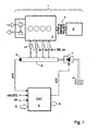
- FIG. 1 shows a system diagram of the overall system of a drive unit 1, for example, an internal combustion engine generator unit.
- This consists of an internal combustion engine 2 with an engine load 4.
- the internal combustion engine 2 drives the engine load 4 via a shaft with a transmission member 3.
- the fuel is injected via a common rail system.
- This comprises the following components: pumps 7 with suction throttle for conveying the fuel from a fuel tank 6, a rail 8 for storing the fuel and injectors 10 for injecting the fuel from the rail 8 into the combustion chambers of the internal combustion engine 2.
- the operation of the internal combustion engine 2 is controlled by an electronic control unit (EDC) 5.
- the electronic control unit 5 includes the usual components of a microcomputer system, such as a microprocessor, I / O devices, buffers and memory devices (EEPROM, RAM). In the memory modules relevant for the operation of the internal combustion engine 2 operating data in maps / curves are applied. About this calculates the electronic control unit 5 from the input variables, the output variables.
- FIG. 1 the following input variables are shown by way of example: a rail pressure pCR, which is measured by means of a rail pressure sensor 9, an actual speed signal nM (IST) of the internal combustion engine 2, an input quantity E and a signal FP for desired output specification by the operator. In a vehicle application, this corresponds to the accelerator pedal position. Under the input E, for example, the charge air pressure of a turbocharger and the temperatures of the coolant / lubricant and the fuel are subsumed.
- FIG. 1 are shown as outputs of the electronic control unit 5, a signal ADV for controlling the pump 7 with suction throttle and an output size A.
- the output variable A is representative of the further control signals for controlling and regulating the internal combustion engine 2, for example, the start of injection SB and a power-determining signal ve, according to the injection quantity.
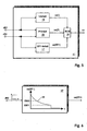
- FIG. 2 a block diagram of the speed control loop is shown.
- the input variable of the speed control loop is a setpoint speed nM (SL).
- the output variable of the speed control loop is the unfiltered actual speed nM (IST).
- a first filter 12 is provided for calculating the first actual rotational speed nM1 (IST) from the current unfiltered actual rotational speed nM (IST).
- the first filter 12 is usually designed as a two-revolution filter, ie it averages the actual rotational speed nM (IST) over a working cycle corresponding to 720 degrees of the crankshaft.
- a second filter 13 is provided for calculating a second actual rotational speed nM2 (IST) from the current unfiltered actual rotational speed nM (IST).
- the second filter 13 is z. B. realized as an average filter with a filter angle of 90 degrees crankshaft angle. The second filter 13 thus has a much greater dynamic than the first filter 12.
- a first control deviation dR1 is calculated. This is determined from the setpoint speed nM (SL) and the first actual speed nM1 (IST).
- the first control deviation dR1 is the input variable of the speed controller 11.
- a second control deviation dR2 is calculated. This is determined from the setpoint speed nM (SL) and the second actual speed nM2 (IST).
- the second control deviation dR2 is also performed on the speed controller 11.
- the internal structure of the speed regulator 11 will be described in connection with the description of Figures 3 or 5 explained. From the input variables, the speed controller 11 determines a manipulated variable. In FIG. 2 this manipulated variable is referred to as a power-determining signal ve.
- the power-determining signal ve represents the input variable for the controlled system, here the internal combustion engine 2.
- the output variable of the controlled system corresponds to the unfiltered actual speed nM (IST). This closes the control loop.
- the invention is embodied in the form that, in the case of a stationary state of the drive unit, the speed controller 11 calculates the power-determining signal ve exclusively as a function of the first control deviation dR1. In the case of a dynamic state change, the speed controller 11 determines the power-determining signal ve as a function of the first control deviation dR1 and the second control deviation dR2.
- the factor kp1 can be specified either as a constant or as a function of the first actual rotational speed nM1 (IST) and / or the I-fraction ve (I).
- This embodiment is in FIG. 3 shown in dashed lines. About the summation 18 of the P and I portion are summed. The sum corresponds to the power-determining signal ve.
- FIG. 5 a second embodiment of the internal structure of the speed controller 11 is shown as a block diagram.
- the second control deviation dR2 is fed to the P-component 15 and parallel to a DT1-component 17.
- the DT1 component 17 is used to calculate the DT1 component ve (DT1) of the power-determining signal ve.
- the summation 18 then calculates the power-determining signal ve from the summands of the P, I and DT1 components.
- the DT1 component 17 is calculated by means of a characteristic curve 19. This is in FIG. 6 shown.
- the time t is plotted on the abscissa.
- the ordinate corresponds to the DT1 component ve (DT1) of the power-determining signal ve.
- the diagram shows two limit values GW1 and GW2.
- the DT1 component is deactivated when the second control deviation dR2 becomes smaller than the first limiting value GW1, ie the signal ve (DT1) then has a significance of zero.
- the DT1 component is activated when the second control deviation dR2 becomes greater than the second threshold GW2.
- the limit value GW2 causes the DT1 component to be included in the calculation of the power-determining signal ve in the case of dynamic state changes, that is to say a large positive or negative second control deviation dR2. For stationary conditions, ie the second control deviation dR2 is almost Zero, the power-determining signal ve is determined exclusively from the P and I components.
Landscapes
- Engineering & Computer Science (AREA)
- Chemical & Material Sciences (AREA)
- Combustion & Propulsion (AREA)
- Mechanical Engineering (AREA)
- General Engineering & Computer Science (AREA)
- Physics & Mathematics (AREA)
- General Physics & Mathematics (AREA)
- Automation & Control Theory (AREA)
- Electrical Control Of Air Or Fuel Supplied To Internal-Combustion Engine (AREA)
- Combined Controls Of Internal Combustion Engines (AREA)
Claims (10)
- Procédé de régulation du régime d'un moteur à combustion interne (2), dans lequel
un premier régime effectif filtré (nM1(IST)) est calculé au moyen d'un premier filtre (12) à partir du régime effectif (nM(IST)) du moteur à combustion interne (2),
un premier écart de réglage (dR1) est calculé à partir d'un régime de consigne (nM(SL)) du moteur à combustion interne (2) et du premier régime effectif filtré (nM1(IST)),
un signal (ve) de détermination de puissance utilisé pour réguler le régime du moteur à combustion interne (2) est déterminé à partir du premier écart de réglage (dR1) au moyen d'un régulateur de régime (11),
caractérisé en ce que
un deuxième régime effectif filtré (nM2(IST)) est calculé au moyen d'un deuxième filtre (13) à partir du régime effectif (nM(IST)) du moteur à combustion interne (2),
en ce qu'un deuxième écart de réglage (dR2) est calculé à partir du régime de consigne (nM(SL)) et du deuxième régime effectif filtré (nM2(IST)) et
en ce qu'en cas de modification dynamique d'état, le signal (ve) de détermination de puissance qui assure la régulation du régime du moteur à combustion interne (2) est calculé au moyen du régulateur de régime (11) à partir du premier écart de réglage (dR1) et du deuxième écart de réglage (dR2). - Procédé de régulation du régime d'un moteur à combustion interne (2) selon la revendication 1, caractérisé en ce que la modification dynamique d'état est détectée par l'intermédiaire du deuxième écart de réglage (dR2).
- Procédé de régulation du régime d'un moteur à combustion interne (2) selon la revendication 1, caractérisé en ce que l'angle de filtrage du deuxième filtre (13) est inférieur à l'angle de filtrage du premier filtre (12).
- Procédé de régulation du régime d'un moteur à combustion interne (2) selon la revendication 2, caractérisé en ce que le deuxième écart de réglage (dR2) agit sur une partie P (15) du régulateur de régime (11).
- Procédé de régulation du régime d'un moteur à combustion interne (2) selon la revendication 4, caractérisé en ce que la partie P (15) est déterminée à partir du premier écart de réglage (dR1), d'un premier facteur (kp1) et d'un deuxième facteur (kp2), le deuxième facteur (kp2) étant calculé à partir du deuxième écart de réglage (dR2) au moyen d'une ligne caractéristique (14).
- Procédé de régulation du régime d'un moteur à combustion interne (2) selon la revendication 5, caractérisé en ce que la partie P est de plus calculée à partir du deuxième écart de réglage (dR2).
- Procédé de régulation du régime d'un moteur à combustion interne (2) selon l'une des revendications 5 ou 6, caractérisé en ce que le premier facteur (kp1) est soit prédéterminé en tant que constante soit calculé en fonction du premier régime filtré (nM1(IST)) et/ou d'une partie I (ve(I)).
- Procédé de régulation du régime d'un moteur à combustion interne (2) selon la revendication 2, caractérisé en ce que le deuxième écart de réglage (dR2) agit sur une partie DT1 (17) du régulateur de régime (11).
- Procédé de régulation du régime d'un moteur à combustion interne (2) selon la revendication 8, caractérisé en ce que la partie DT1 (17) est déterminée à partir du deuxième écart de réglage (dR2) par l'intermédiaire d'une ligne caractéristique (19).
- Procédé de régulation du régime d'un moteur à combustion interne (2) selon la revendication 9, caractérisé en ce qu'au moyen de la ligne caractéristique (19), la partie Dt1 (17) est désactivée lorsque le deuxième écart de réglage (dR2) est inférieur à une première valeur limite (GW1) (dR2 < GW1) et en ce que la partie DT1 est activée lorsque le deuxième écart de réglage (dR2) est plus grand qu'une deuxième valeur limite (GW2) (dR2 > GW2).
Applications Claiming Priority (3)
| Application Number | Priority Date | Filing Date | Title |
|---|---|---|---|
| DE10253739 | 2002-11-19 | ||
| DE10253739A DE10253739B3 (de) | 2002-11-19 | 2002-11-19 | Verfahren zur Drehzahl-Regelung einer Brennkraftmaschine |
| PCT/EP2003/012786 WO2004046527A1 (fr) | 2002-11-19 | 2003-11-15 | Procede pour reguler le regime d'un moteur a combustion interne |
Publications (2)
| Publication Number | Publication Date |
|---|---|
| EP1563176A1 EP1563176A1 (fr) | 2005-08-17 |
| EP1563176B1 true EP1563176B1 (fr) | 2010-01-13 |
Family
ID=32087357
Family Applications (1)
| Application Number | Title | Priority Date | Filing Date |
|---|---|---|---|
| EP03775361A Expired - Lifetime EP1563176B1 (fr) | 2002-11-19 | 2003-11-15 | Procede pour reguler le regime d'un moteur a combustion interne |
Country Status (4)
| Country | Link |
|---|---|
| US (1) | US7069904B2 (fr) |
| EP (1) | EP1563176B1 (fr) |
| DE (2) | DE10253739B3 (fr) |
| WO (1) | WO2004046527A1 (fr) |
Families Citing this family (12)
| Publication number | Priority date | Publication date | Assignee | Title |
|---|---|---|---|---|
| DE102004023365B4 (de) | 2004-05-12 | 2007-07-19 | Mtu Friedrichshafen Gmbh | Verfahren zur Druck-Regelung eines Speichereinspritzsystems |
| DE102005004441B3 (de) * | 2005-01-31 | 2006-02-09 | Siemens Ag | Vorrichtung und Verfahren zum Ermitteln einer Stellgröße eines Reglers einer Brennkraftmaschine |
| DE102005042650B4 (de) * | 2005-09-08 | 2017-10-12 | Robert Bosch Gmbh | Drehzahlregelung für eine Brennkraftmaschine im Sturzgasfall |
| DE102007018805B4 (de) * | 2007-03-29 | 2009-01-29 | Universität Kassel | Verfahren zur Regelung zyklischer Prozesse |
| DE102007032484A1 (de) * | 2007-07-12 | 2009-01-22 | Beckhoff Automation Gmbh | Regelverfahren und Regelvorrichtung mit mehrkanaliger Rückführung |
| US8517134B1 (en) | 2007-10-30 | 2013-08-27 | Daniel Albanesi | Method and system for engine control |
| FI125798B (fi) | 2008-03-03 | 2016-02-29 | Wã Rtsilã Finland Oy | Mäntämoottorin nopeussäädin |
| DE102008036299B3 (de) | 2008-08-04 | 2009-12-03 | Mtu Friedrichshafen Gmbh | Verfahren zur Druckregelung |
| EP2192292B1 (fr) * | 2008-11-28 | 2017-04-26 | Caterpillar Motoren GmbH & Co. KG | Régulateur de vitesse de rotation |
| DE102011103988A1 (de) * | 2011-06-10 | 2012-12-13 | Mtu Friedrichshafen Gmbh | Verfahren zur Raildruckregelung |
| AT516817A1 (de) | 2015-01-23 | 2016-08-15 | Ge Jenbacher Gmbh & Co Og | Verfahren zum Betreiben einer Anordnung umfassend eine rotierende Arbeitsmaschine |
| JP7079164B2 (ja) | 2018-07-06 | 2022-06-01 | 株式会社荏原製作所 | 基板洗浄装置および基板洗浄方法 |
Family Cites Families (15)
| Publication number | Priority date | Publication date | Assignee | Title |
|---|---|---|---|---|
| DE59585C (de) | L. G. ARNOLD in City of Menasha, Nr. 17 Main Street, County of Winnebago, Wisconsin, V. St. A | Selbstwirkende Bremse | ||
| DE2816613A1 (de) * | 1978-04-17 | 1979-10-25 | Vdo Adolf Schindling A | Einrichtung zum regeln der fahrgeschwindigkeit eines kraftfahrzeugs |
| US4495913A (en) * | 1983-03-15 | 1985-01-29 | Dana Corporation | Ignition current sensor for an electronic speed control system |
| US4715339A (en) | 1984-09-01 | 1987-12-29 | Kawasaki Jukogyo Kabushiki Kaisha | Governor for internal combustion engine |
| US5235512A (en) * | 1991-06-24 | 1993-08-10 | Ford Motor Company | Self-tuning speed control for a vehicle |
| FR2766872B1 (fr) * | 1997-08-01 | 1999-10-15 | Renault | Procede de correction des a-coups de couple d'un moteur a combustion interne |
| DE19741965C1 (de) * | 1997-09-23 | 1999-01-21 | Siemens Ag | Verfahren zur Laufruheregelung |
| DE19753996A1 (de) * | 1997-12-05 | 1999-06-10 | Siemens Ag | Verfahren zum Dämpfen von Ruckelschwingungen oder Lastschlägen bei einer Brennkraftmaschine |
| DE19833839C2 (de) | 1998-07-28 | 2001-02-08 | Bosch Gmbh Robert | Verfahren und Vorrichtung zur Steuerung einer Kraftstoffzumeßeinrichtung |
| US6196189B1 (en) * | 1999-06-18 | 2001-03-06 | Caterpillar Inc. | Method and apparatus for controlling the speed of an engine |
| DE19953767C2 (de) * | 1999-11-09 | 2002-03-28 | Mtu Friedrichshafen Gmbh | Regelsystem zum Schutz einer Brennkraftmaschine vor Überlast |
| DE10122517C1 (de) | 2001-05-09 | 2002-06-20 | Mtu Friedrichshafen Gmbh | Drehzahl-Filter |
| ITTO20010660A1 (it) * | 2001-07-06 | 2003-01-06 | Fiat Ricerche | Motore diesel pluricilindrico con azionamento variabile delle valvole. |
| DE10221681B4 (de) * | 2002-05-16 | 2005-12-08 | Mtu Friedrichshafen Gmbh | Verfahren zur Regelung einer Brennkraftmaschinen-Generator-Einheit |
| DE102004008261B3 (de) * | 2004-02-20 | 2005-09-29 | Mtu Friedrichshafen Gmbh | Verfahren zur Steuerung und Regelung einer Brennkraftmaschinen-Generator-Einheit |
-
2002
- 2002-11-19 DE DE10253739A patent/DE10253739B3/de not_active Expired - Fee Related
-
2003
- 2003-11-15 WO PCT/EP2003/012786 patent/WO2004046527A1/fr active Application Filing
- 2003-11-15 EP EP03775361A patent/EP1563176B1/fr not_active Expired - Lifetime
- 2003-11-15 DE DE50312346T patent/DE50312346D1/de not_active Expired - Lifetime
- 2003-11-15 US US10/533,845 patent/US7069904B2/en not_active Expired - Lifetime
Also Published As
| Publication number | Publication date |
|---|---|
| DE10253739B3 (de) | 2004-05-06 |
| WO2004046527A1 (fr) | 2004-06-03 |
| US20060011167A1 (en) | 2006-01-19 |
| EP1563176A1 (fr) | 2005-08-17 |
| DE50312346D1 (de) | 2010-03-04 |
| US7069904B2 (en) | 2006-07-04 |
| WO2004046527A8 (fr) | 2004-08-26 |
Similar Documents
| Publication | Publication Date | Title |
|---|---|---|
| DE19739565B4 (de) | Verfahren und Vorrichtung zur Steuerung des Drehmoments einer Antriebseinheit eines Kraftfahrzeugs | |
| DE19536038B4 (de) | Verfahren und Vorrichtung zur Steuerung der Antriebseinheit eines Kraftfahrzeugs | |
| EP1563176B1 (fr) | Procede pour reguler le regime d'un moteur a combustion interne | |
| DE4017429C2 (de) | Steuervorrichtung für die Bewegung eines Fahrzeuges | |
| DE112010004861B4 (de) | Fahrzeugsteuersystem und Fahrzeugsteuerverfahren | |
| EP2379390B1 (fr) | Procédé et dispositif pour le fonctionnement d'un véhicule hybride | |
| EP0939212B1 (fr) | Méthode et dispositif de contrôle d'un moteur automobile avec correction du couple de propulsion | |
| DE19836845B4 (de) | Verfahren und Vorrichtung zur Steuerung einer Antriebseinheit eines Kraftfahrzeugs | |
| DE3884774T2 (de) | System und Verfahren zur Steuerung der Drehbewegung des Antriebsrades für Fahrzeuge. | |
| DE102014225920B4 (de) | Verfahren zum Betrieb eines Dieselmotors | |
| DE10060625B4 (de) | Steuersystem für eine mit einem Automatikgetriebe ausgerüstete Brennkraftmaschine | |
| EP1504521B1 (fr) | Procede de regulation d'une unite generateur/moteur a combustion interne | |
| DE4333896B4 (de) | Verfahren und Vorrichtung zur Steuerung einer Brennkraftmaschine | |
| DE19756844B4 (de) | Hydrauliksteuervorrichtung eines Automatikgetriebes | |
| DE19708243C1 (de) | Verfahren und Einrichtung zum Steuern einer Brennkraftmaschine | |
| WO2004065773A1 (fr) | Procede pour reguler le regime d'un moteur a combustion interne | |
| DE10248633B4 (de) | Verfahren zur Drehzahl-Regelung einer Antriebseinheit | |
| DE102007013253A1 (de) | Verfahren und Vorrichtung zum Betreiben einer Antriebseinheit | |
| DE19809512C2 (de) | Vorrichtung zur Einstellung einer Drosselklappe | |
| DE102004015973B3 (de) | Verfahren zur Steuerung und Regelung einer Brennkraftmaschinen-Generator-Einheit | |
| DE102016201588A1 (de) | Verfahren zur Einstellung eines hydrostatischen Fahrantriebs | |
| DE4223253A1 (de) | Steuereinrichtung für ein Fahrzeug | |
| DE102019205402A1 (de) | Regelung einer Abtriebsdrehzahl bei einem hydrostatischen Fahrantrieb | |
| DE4020654C2 (de) | Regelverfahren in Verbindung mit einer Brennkraftmaschine und/oder einem Kraftfahrzeug und Regelvorrichtung zur Durchführung des Regelverfahrens | |
| DE10305092B4 (de) | Verfahren zur automatischen Anpassung eines Drehmomentenmodells sowie Schaltungsanordnung |
Legal Events
| Date | Code | Title | Description |
|---|---|---|---|
| PUAI | Public reference made under article 153(3) epc to a published international application that has entered the european phase |
Free format text: ORIGINAL CODE: 0009012 |
|
| 17P | Request for examination filed |
Effective date: 20050512 |
|
| AK | Designated contracting states |
Kind code of ref document: A1 Designated state(s): AT BE BG CH CY CZ DE DK EE ES FI FR GB GR HU IE IT LI LU MC NL PT RO SE SI SK TR |
|
| RBV | Designated contracting states (corrected) |
Designated state(s): DE FR GB |
|
| GRAP | Despatch of communication of intention to grant a patent |
Free format text: ORIGINAL CODE: EPIDOSNIGR1 |
|
| GRAS | Grant fee paid |
Free format text: ORIGINAL CODE: EPIDOSNIGR3 |
|
| GRAA | (expected) grant |
Free format text: ORIGINAL CODE: 0009210 |
|
| AK | Designated contracting states |
Kind code of ref document: B1 Designated state(s): DE FR GB |
|
| REG | Reference to a national code |
Ref country code: GB Ref legal event code: FG4D Free format text: NOT ENGLISH |
|
| REF | Corresponds to: |
Ref document number: 50312346 Country of ref document: DE Date of ref document: 20100304 Kind code of ref document: P |
|
| PLBE | No opposition filed within time limit |
Free format text: ORIGINAL CODE: 0009261 |
|
| STAA | Information on the status of an ep patent application or granted ep patent |
Free format text: STATUS: NO OPPOSITION FILED WITHIN TIME LIMIT |
|
| 26N | No opposition filed |
Effective date: 20101014 |
|
| REG | Reference to a national code |
Ref country code: FR Ref legal event code: PLFP Year of fee payment: 13 |
|
| REG | Reference to a national code |
Ref country code: FR Ref legal event code: PLFP Year of fee payment: 14 |
|
| REG | Reference to a national code |
Ref country code: FR Ref legal event code: PLFP Year of fee payment: 15 |
|
| REG | Reference to a national code |
Ref country code: DE Ref legal event code: R081 Ref document number: 50312346 Country of ref document: DE Owner name: ROLLS-ROYCE SOLUTIONS GMBH, DE Free format text: FORMER OWNER: MTU FRIEDRICHSHAFEN GMBH, 88045 FRIEDRICHSHAFEN, DE |
|
| PGFP | Annual fee paid to national office [announced via postgrant information from national office to epo] |
Ref country code: GB Payment date: 20221125 Year of fee payment: 20 Ref country code: FR Payment date: 20221128 Year of fee payment: 20 Ref country code: DE Payment date: 20220706 Year of fee payment: 20 |
|
| P01 | Opt-out of the competence of the unified patent court (upc) registered |
Effective date: 20230529 |
|
| REG | Reference to a national code |
Ref country code: DE Ref legal event code: R071 Ref document number: 50312346 Country of ref document: DE |
|
| REG | Reference to a national code |
Ref country code: GB Ref legal event code: PE20 Expiry date: 20231114 |
|
| PG25 | Lapsed in a contracting state [announced via postgrant information from national office to epo] |
Ref country code: GB Free format text: LAPSE BECAUSE OF EXPIRATION OF PROTECTION Effective date: 20231114 |
|
| PG25 | Lapsed in a contracting state [announced via postgrant information from national office to epo] |
Ref country code: GB Free format text: LAPSE BECAUSE OF EXPIRATION OF PROTECTION Effective date: 20231114 |