EP1563176B1 - Verfahren zur drehzahl-regelung einer brennkraftmaschine - Google Patents
Verfahren zur drehzahl-regelung einer brennkraftmaschine Download PDFInfo
- Publication number
- EP1563176B1 EP1563176B1 EP03775361A EP03775361A EP1563176B1 EP 1563176 B1 EP1563176 B1 EP 1563176B1 EP 03775361 A EP03775361 A EP 03775361A EP 03775361 A EP03775361 A EP 03775361A EP 1563176 B1 EP1563176 B1 EP 1563176B1
- Authority
- EP
- European Patent Office
- Prior art keywords
- speed
- regulating
- internal combustion
- combustion engine
- factor
- Prior art date
- Legal status (The legal status is an assumption and is not a legal conclusion. Google has not performed a legal analysis and makes no representation as to the accuracy of the status listed.)
- Expired - Lifetime
Links
- 238000002485 combustion reaction Methods 0.000 title claims description 35
- 230000001105 regulatory effect Effects 0.000 title claims description 28
- 238000000034 method Methods 0.000 title claims description 14
- 230000008859 change Effects 0.000 claims description 8
- 238000010586 diagram Methods 0.000 description 8
- 239000000446 fuel Substances 0.000 description 5
- 230000006870 function Effects 0.000 description 4
- 238000002347 injection Methods 0.000 description 4
- 239000007924 injection Substances 0.000 description 4
- 230000005540 biological transmission Effects 0.000 description 3
- 230000001276 controlling effect Effects 0.000 description 3
- 239000002828 fuel tank Substances 0.000 description 2
- 238000012935 Averaging Methods 0.000 description 1
- 230000008901 benefit Effects 0.000 description 1
- 239000000872 buffer Substances 0.000 description 1
- 239000002826 coolant Substances 0.000 description 1
- 230000008878 coupling Effects 0.000 description 1
- 238000010168 coupling process Methods 0.000 description 1
- 238000005859 coupling reaction Methods 0.000 description 1
- 238000001514 detection method Methods 0.000 description 1
- 230000006866 deterioration Effects 0.000 description 1
- 239000000314 lubricant Substances 0.000 description 1
- 239000013642 negative control Substances 0.000 description 1
- 230000008569 process Effects 0.000 description 1
Images


Classifications
-
- F—MECHANICAL ENGINEERING; LIGHTING; HEATING; WEAPONS; BLASTING
- F02—COMBUSTION ENGINES; HOT-GAS OR COMBUSTION-PRODUCT ENGINE PLANTS
- F02D—CONTROLLING COMBUSTION ENGINES
- F02D41/00—Electrical control of supply of combustible mixture or its constituents
- F02D41/02—Circuit arrangements for generating control signals
- F02D41/0205—Circuit arrangements for generating control signals using an auxiliary engine speed control
-
- F—MECHANICAL ENGINEERING; LIGHTING; HEATING; WEAPONS; BLASTING
- F02—COMBUSTION ENGINES; HOT-GAS OR COMBUSTION-PRODUCT ENGINE PLANTS
- F02D—CONTROLLING COMBUSTION ENGINES
- F02D31/00—Use of speed-sensing governors to control combustion engines, not otherwise provided for
- F02D31/001—Electric control of rotation speed
-
- F—MECHANICAL ENGINEERING; LIGHTING; HEATING; WEAPONS; BLASTING
- F02—COMBUSTION ENGINES; HOT-GAS OR COMBUSTION-PRODUCT ENGINE PLANTS
- F02D—CONTROLLING COMBUSTION ENGINES
- F02D41/00—Electrical control of supply of combustible mixture or its constituents
- F02D41/02—Circuit arrangements for generating control signals
- F02D41/14—Introducing closed-loop corrections
- F02D41/1401—Introducing closed-loop corrections characterised by the control or regulation method
- F02D41/1402—Adaptive control
-
- G—PHYSICS
- G05—CONTROLLING; REGULATING
- G05B—CONTROL OR REGULATING SYSTEMS IN GENERAL; FUNCTIONAL ELEMENTS OF SUCH SYSTEMS; MONITORING OR TESTING ARRANGEMENTS FOR SUCH SYSTEMS OR ELEMENTS
- G05B11/00—Automatic controllers
- G05B11/01—Automatic controllers electric
- G05B11/36—Automatic controllers electric with provision for obtaining particular characteristics, e.g. proportional, integral, differential
- G05B11/42—Automatic controllers electric with provision for obtaining particular characteristics, e.g. proportional, integral, differential for obtaining a characteristic which is both proportional and time-dependent, e.g. P. I., P. I. D.
-
- F—MECHANICAL ENGINEERING; LIGHTING; HEATING; WEAPONS; BLASTING
- F02—COMBUSTION ENGINES; HOT-GAS OR COMBUSTION-PRODUCT ENGINE PLANTS
- F02D—CONTROLLING COMBUSTION ENGINES
- F02D41/00—Electrical control of supply of combustible mixture or its constituents
- F02D41/02—Circuit arrangements for generating control signals
- F02D41/14—Introducing closed-loop corrections
- F02D41/1401—Introducing closed-loop corrections characterised by the control or regulation method
- F02D2041/1409—Introducing closed-loop corrections characterised by the control or regulation method using at least a proportional, integral or derivative controller
-
- F—MECHANICAL ENGINEERING; LIGHTING; HEATING; WEAPONS; BLASTING
- F02—COMBUSTION ENGINES; HOT-GAS OR COMBUSTION-PRODUCT ENGINE PLANTS
- F02D—CONTROLLING COMBUSTION ENGINES
- F02D41/00—Electrical control of supply of combustible mixture or its constituents
- F02D41/02—Circuit arrangements for generating control signals
- F02D41/14—Introducing closed-loop corrections
- F02D41/1401—Introducing closed-loop corrections characterised by the control or regulation method
- F02D2041/1413—Controller structures or design
- F02D2041/1418—Several control loops, either as alternatives or simultaneous
- F02D2041/1419—Several control loops, either as alternatives or simultaneous the control loops being cascaded, i.e. being placed in series or nested
-
- F—MECHANICAL ENGINEERING; LIGHTING; HEATING; WEAPONS; BLASTING
- F02—COMBUSTION ENGINES; HOT-GAS OR COMBUSTION-PRODUCT ENGINE PLANTS
- F02D—CONTROLLING COMBUSTION ENGINES
- F02D41/00—Electrical control of supply of combustible mixture or its constituents
- F02D41/02—Circuit arrangements for generating control signals
- F02D41/14—Introducing closed-loop corrections
- F02D41/1401—Introducing closed-loop corrections characterised by the control or regulation method
- F02D2041/1413—Controller structures or design
- F02D2041/1422—Variable gain or coefficients
Definitions
- the invention relates to a method for speed control of an internal combustion engine according to the preamble of claim 1.
- the speed of a drive unit is typically controlled to an idle and final speed.
- Drive unit is understood to mean both an internal combustion engine transmission unit and an internal combustion engine generator unit.
- speed control the speed of the crankshaft is detected as a controlled variable and compared with a motor speed setpoint, the reference variable.
- the resulting control deviation is converted via a speed controller into a manipulated variable for the internal combustion engine, for example an injection quantity.
- a speed controller One problem with such a control circuit is that torsional vibrations which are superimposed on the controlled variable can be amplified by the speed controller. This can lead to instability of the control loop.
- a speed filter in the feedback loop of the speed control loop. From the EP 0 059 585 B1 Such a speed filter is known.
- the tooth times of a shaft are detected via a working cycle of the internal combustion engine. Under working cycle are two revolutions of the crankshaft, corresponding to 720 degrees to understand. From these teeth times, a filtered tooth time is then calculated using arithmetic averaging. This is updated after each work cycle.
- This filtered tooth time corresponds to the filtered actual speed value, which is then used to control the internal combustion engine.
- a speed control loop for controlling a drive unit with such a speed filter in the feedback branch is for example from DE 199 53 767 C2 known.
- a problem with a two-revolution filter in the feedback branch is that a stable behavior of the drive unit is accompanied by a deterioration of the load-acceptance behavior.
- the invention is based on the object of optimizing a speed control circuit with respect to the load acceptance behavior.
- the invention provides that a second filtered actual speed is calculated from the actual speed of the internal combustion engine by means of a second filter, from which then a second control deviation is calculated.
- the speed controller calculates a power-determining signal, for example an injection quantity, from the first and the second control deviation.
- the power-determining signal is decisively determined from the second control deviation in the case of a dynamic state change.
- a dynamic state change occurs when there is a large desired-actual deviation of the rotational speeds, for example during a load or load shutdown.
- the second filter z. B. executed as an average filter with a filter angle of 90 degrees. Compared with the two-revolution filter, a filtered speed value is available at a much earlier point in time, ie the dynamic state change is detected more quickly.
- the invention offers the advantage that couplings can be used with low natural frequency. Since the second filter represents a pure software solution, it can be integrated later into an existing engine control software.
- the second control deviation acts on a P component (proportional component) or a DT1 component of the rpm controller.
- P component proportional component
- DT1 component of the rpm controller
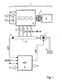
- FIG. 1 shows a system diagram of the overall system of a drive unit 1, for example, an internal combustion engine generator unit.
- This consists of an internal combustion engine 2 with an engine load 4.
- the internal combustion engine 2 drives the engine load 4 via a shaft with a transmission member 3.
- the fuel is injected via a common rail system.
- This comprises the following components: pumps 7 with suction throttle for conveying the fuel from a fuel tank 6, a rail 8 for storing the fuel and injectors 10 for injecting the fuel from the rail 8 into the combustion chambers of the internal combustion engine 2.
- the operation of the internal combustion engine 2 is controlled by an electronic control unit (EDC) 5.
- the electronic control unit 5 includes the usual components of a microcomputer system, such as a microprocessor, I / O devices, buffers and memory devices (EEPROM, RAM). In the memory modules relevant for the operation of the internal combustion engine 2 operating data in maps / curves are applied. About this calculates the electronic control unit 5 from the input variables, the output variables.
- FIG. 1 the following input variables are shown by way of example: a rail pressure pCR, which is measured by means of a rail pressure sensor 9, an actual speed signal nM (IST) of the internal combustion engine 2, an input quantity E and a signal FP for desired output specification by the operator. In a vehicle application, this corresponds to the accelerator pedal position. Under the input E, for example, the charge air pressure of a turbocharger and the temperatures of the coolant / lubricant and the fuel are subsumed.
- FIG. 1 are shown as outputs of the electronic control unit 5, a signal ADV for controlling the pump 7 with suction throttle and an output size A.
- the output variable A is representative of the further control signals for controlling and regulating the internal combustion engine 2, for example, the start of injection SB and a power-determining signal ve, according to the injection quantity.
- FIG. 2 a block diagram of the speed control loop is shown.
- the input variable of the speed control loop is a setpoint speed nM (SL).
- the output variable of the speed control loop is the unfiltered actual speed nM (IST).
- a first filter 12 is provided for calculating the first actual rotational speed nM1 (IST) from the current unfiltered actual rotational speed nM (IST).
- the first filter 12 is usually designed as a two-revolution filter, ie it averages the actual rotational speed nM (IST) over a working cycle corresponding to 720 degrees of the crankshaft.
- a second filter 13 is provided for calculating a second actual rotational speed nM2 (IST) from the current unfiltered actual rotational speed nM (IST).
- the second filter 13 is z. B. realized as an average filter with a filter angle of 90 degrees crankshaft angle. The second filter 13 thus has a much greater dynamic than the first filter 12.
- a first control deviation dR1 is calculated. This is determined from the setpoint speed nM (SL) and the first actual speed nM1 (IST).
- the first control deviation dR1 is the input variable of the speed controller 11.
- a second control deviation dR2 is calculated. This is determined from the setpoint speed nM (SL) and the second actual speed nM2 (IST).
- the second control deviation dR2 is also performed on the speed controller 11.
- the internal structure of the speed regulator 11 will be described in connection with the description of Figures 3 or 5 explained. From the input variables, the speed controller 11 determines a manipulated variable. In FIG. 2 this manipulated variable is referred to as a power-determining signal ve.
- the power-determining signal ve represents the input variable for the controlled system, here the internal combustion engine 2.
- the output variable of the controlled system corresponds to the unfiltered actual speed nM (IST). This closes the control loop.
- the invention is embodied in the form that, in the case of a stationary state of the drive unit, the speed controller 11 calculates the power-determining signal ve exclusively as a function of the first control deviation dR1. In the case of a dynamic state change, the speed controller 11 determines the power-determining signal ve as a function of the first control deviation dR1 and the second control deviation dR2.
- the factor kp1 can be specified either as a constant or as a function of the first actual rotational speed nM1 (IST) and / or the I-fraction ve (I).
- This embodiment is in FIG. 3 shown in dashed lines. About the summation 18 of the P and I portion are summed. The sum corresponds to the power-determining signal ve.
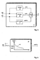
- FIG. 5 a second embodiment of the internal structure of the speed controller 11 is shown as a block diagram.
- the second control deviation dR2 is fed to the P-component 15 and parallel to a DT1-component 17.
- the DT1 component 17 is used to calculate the DT1 component ve (DT1) of the power-determining signal ve.
- the summation 18 then calculates the power-determining signal ve from the summands of the P, I and DT1 components.
- the DT1 component 17 is calculated by means of a characteristic curve 19. This is in FIG. 6 shown.
- the time t is plotted on the abscissa.
- the ordinate corresponds to the DT1 component ve (DT1) of the power-determining signal ve.
- the diagram shows two limit values GW1 and GW2.
- the DT1 component is deactivated when the second control deviation dR2 becomes smaller than the first limiting value GW1, ie the signal ve (DT1) then has a significance of zero.
- the DT1 component is activated when the second control deviation dR2 becomes greater than the second threshold GW2.
- the limit value GW2 causes the DT1 component to be included in the calculation of the power-determining signal ve in the case of dynamic state changes, that is to say a large positive or negative second control deviation dR2. For stationary conditions, ie the second control deviation dR2 is almost Zero, the power-determining signal ve is determined exclusively from the P and I components.
Landscapes
- Engineering & Computer Science (AREA)
- Chemical & Material Sciences (AREA)
- Combustion & Propulsion (AREA)
- Mechanical Engineering (AREA)
- General Engineering & Computer Science (AREA)
- Physics & Mathematics (AREA)
- General Physics & Mathematics (AREA)
- Automation & Control Theory (AREA)
- Electrical Control Of Air Or Fuel Supplied To Internal-Combustion Engine (AREA)
- Combined Controls Of Internal Combustion Engines (AREA)
Description
- Die Erfindung betrifft ein Verfahren zur Drehzahl-Regelung einer Brennkraftmaschine nach dem Oberbegriff von Anspruch 1.
- Die Drehzahl einer Antriebseinheit wird typischerweise auf eine Leerlauf- und Enddrehzahl geregelt. Unter Antriebseinheit ist sowohl eine Brennkraftmaschinen-Getriebeeinheit als auch eine Brennkraftmaschinen-Generatoreinheit zu verstehen. Zur Drehzahl-Regelung wird die Drehzahl der Kurbelwelle als Regelgröße erfasst und mit einem Motordrehzahl-Sollwert, der Führungsgröße, verglichen. Die daraus resultierende Regelabweichung wird über einen Drehzahl-Regler in eine Stellgröße für die Brennkraftmaschine, beispielsweise eine Einspritzmenge, gewandelt. Bei einem derartigen Regelkreis besteht ein Problem darin, dass Drehschwingungen, die der Regelgröße überlagert sind, vom Drehzahl-Regler verstärkt werden können. Dies kann zu einer Instabilität des Regelkreises führen.
- Dem Problem der Instabilität wird durch ein Drehzahl-Filter im Rückkopplungszweig des Drehzahl-Regelkreises begegnet. Aus der
EP 0 059 585 B1 ist ein derartiges Drehzahl-Filter bekannt. Bei diesem werden die Zahnzeiten einer Welle über ein Arbeitsspiel der Brennkraftmaschine erfasst. Unter Arbeitsspiel sind zwei Umdrehungen der Kurbelwelle, entsprechend 720 Grad, zu verstehen. Aus diesen Zahnzeiten wird danach über arithmetische Mittelwertbildung eine gefilterte Zahnzeit berechnet. Aktualisiert wird diese nach jedem Arbeitsspiel. - Diese gefilterte Zahnzeit entspricht dem gefilterten Ist-Drehzahlwert, welcher sodann zur Regelung der Brennkraftmaschine verwendet wird.
- Ein Drehzahl-Regelkreis zur Regelung einer Antriebseinheit mit einem derartigen Drehzahl-Filter im Rückkopplungszweig ist beispielsweise aus der
DE 199 53 767 C2 bekannt. - Problematisch bei einem Zwei-Umdrehungs-Filter im Rückkopplungszweig ist jedoch, dass ein stabiles Verhalten der Antriebseinheit mit einer Verschlechterung des Lastannahme-Verhaltens einhergeht.
- Der Erfindung liegt die Aufgabe zu Grunde einen Drehzahl-Regelkreis in Bezug auf das Lastannahme-Verhalten zu optimieren.
- Die Aufgabe wird durch die Merkmale von Anspruch 1 gelöst.
Die Ausgestaltungen hierzu sind in den Unteransprüchen dargestellt. - Die Erfindung sieht vor, dass aus der Ist-Drehzahl der Brennkraftmaschine mittels eines zweiten Filters eine zweite gefilterte Ist-Drehzahl berechnet wird, aus welcher danach eine zweite Regelabweichung berechnet wird. Bei einer dynamischen Zustandsänderung berechnet der Drehzahl-Regler ein leistungsbestimmendes Signal, beispielsweise eine Einspritzmenge, aus der ersten und der zweiten Regelabweichung. Hierbei wird das leistungsbestimmende Signal bei einer dynamischen Zustandsänderung maßgeblich aus der zweiten Regelabweichung bestimmt.
- Eine dynamische Zustandsänderung liegt dann vor, wenn eine große Soll-Ist-Abweichung der Drehzahlen vorliegt, beispielsweise bei einer Lastauf- oder Lastabschaltung. Zur schnelleren Erkennung dieses dynamischen Vorgangs ist das zweite Filter z. B. als Mittelwertfilter mit einem Filterwinkel von 90 Grad ausgeführt. Gegenüber dem Zwei-Umdrehungs-Filter liegt zu einem wesentlich früheren Zeitpunkt ein gefilterter Drehzahlwert vor, d. h. die dynamische Zustandsänderung wird schneller detektiert.
- Die Erfindung bietet als Vorteil, dass Kupplungen mit niedriger Eigenfrequenz verwendet werden können. Da das zweite Filter eine reine Software-Lösung darstellt, kann es in eine bereits bestehende Motorsteuerungs-Software nachträglich integriert werden.
- Bei einer dynamischen Zustandsänderung ist vorgesehen, dass die zweite Regelabweichung auf einen P-Anteil (proportionalen Anteil) oder einen DT1-Anteil des Drehzahl-Reglers einwirkt. Hierzu sind entsprechende Kennlinien vorgesehen.
- In den Zeichnungen sind die bevorzugten Ausführungsbeispiele der Erfindung dargestellt. Es zeigen:
- Fig. 1
- ein Systemschaubild;
- Fig. 2
- einen Drehzahl-Regelkreis;
- Fig. 3
- ein Blockschaltbild des Drehzahl-Reglers;
- Fig. 4
- eine Kennlinie;
- Fig. 5
- ein Blockschaltbild des Drehzahl-Reglers (zweite Ausführung);
- Fig. 6
- eine Kennlinie.
- Die
Figur 1 zeigt ein Systemschaubild des Gesamtsystems einer Antriebseinheit 1, beispielsweise einer Brennkraftmaschinen-Generatoreinheit. Diese bestehend aus einer Brennkraftmaschine 2 mit einer Motorlast 4. Die Brennkraftmaschine 2 treibt über eine Welle mit einem Übertragungsglied 3 die Motorlast 4 an. Bei der dargestellten Brennkraftmaschine 2 wird der Kraftstoff über ein Common-Rail-System eingespritzt. Dieses umfasst folgende Komponenten: Pumpen 7 mit Saugdrossel zur Förderung des Kraftstoffs aus einem Kraftstofftank 6, ein Rail 8 zum Speichern des Kraftstoffs und Injektoren 10 zum Einspritzen des Kraftstoffs aus dem Rail 8 in die Brennräume der Brennkraftmaschine 2. - Die Betriebsweise der Brennkraftmaschine 2 wird durch ein elektronisches Steuergerät (EDC) 5 geregelt. Das elektronische Steuergerät 5 beinhaltet die üblichen Bestandteile eines Mikrocomputersystems, beispielsweise einen Mikroprozessor, I/O-Bausteine, Puffer und Speicherbausteine (EEPROM, RAM). In den Speicherbausteinen sind die für den Betrieb der Brennkraftmaschine 2 relevanten Betriebsdaten in Kennfeldern/Kennlinien appliziert. Über diese berechnet das elektronische Steuergerät 5 aus den Eingangsgrößen die Ausgangsgrößen. In
Figur 1 sind exemplarisch folgende Eingangsgrößen dargestellt: ein Raildruck pCR, der mittels eines Rail-Drucksensors 9 gemessen wird, ein Ist-Drehzahl-Signal nM(IST) der Brennkraftmaschine 2, eine Eingangsgröße E und ein Signal FP zur Leistungswunsch-Vorgabe durch den Betreiber. Bei einer Fahrzeug-Anwendung entspricht dies der Fahrpedalstellung. Unter der Eingangsgröße E sind beispielsweise der Ladeluftdruck eines Turboladers und die Temperaturen der Kühl-/Schmiermittel und des Kraftstoffs subsumiert. - In
Figur 1 sind als Ausgangsgrößen des elektronischen Steuergeräts 5 ein Signal ADV zur Steuerung der Pumpen 7 mit Saugdrossel und eine Ausgangsgröße A dargestellt. Die Ausgangsgröße A steht stellvertretend für die weiteren Stellsignale zur Steuerung und Regelung der Brennkraftmaschine 2, beispielsweise den Einspritzbeginn SB und ein leistungsbestimmendes Signal ve, entsprechend der Einspritzmenge. - In
Figur 2 ist ein Blockschaltbild des Drehzahl-Regelkreises dargestellt. Die Eingangsgröße des Drehzahl-Regelkreises ist eine Soll-Drehzahl nM(SL). Die Ausgangsgröße des Drehzahl-Regelkreises ist die ungefilterte Ist-Drehzahl nM(IST). In einem ersten Rückkopplungszweig ist ein erstes Filter 12 zur Berechnung der ersten Ist-Drehzahl nM1 (IST) aus der aktuellen ungefilterten Ist-Drehzahl nM(IST) vorgesehen. Das erste Filter 12 ist üblicherweise als ein Zwei-Umdrehungs-Filter ausgeführt, d. h. es mittelt die Ist-Drehzahl nM(IST) über ein Arbeitsspiel entsprechend 720 Grad der Kurbelwelle. In einem zweiten Rückkopplungszweig ist ein zweites Filter 13 zur Berechnung einer zweiten Ist-Drehzahl nM2(IST) aus der aktuellen ungefilterten Ist-Drehzahl nM(IST) vorgesehen. Das zweite Filter 13 ist z. B. als ein Mittelwertfilter mit einem Filterwinkel von 90 Grad Kurbelwellen-Winkel verwirklicht. Das zweite Filter 13 besitzt somit eine wesentlich größere Dynamik als das erste Filter 12. - An einer ersten Vergleichsstelle A wird eine erste Regelabweichung dR1 berechnet. Diese bestimmt sich aus der Soll-Drehzahl nM(SL) und der ersten Ist-Drehzahl nM1(IST). Die erste Regelabweichung dR1 ist die Eingangsgröße des Drehzahl-Reglers 11. An einer zweiten Vergleichsstelle B wird eine zweite Regelabweichung dR2 berechnet. Diese bestimmt sich aus der Soll-Drehzahl nM(SL) und der zweiten Ist-Drehzahl nM2(IST). Die zweite Regelabweichung dR2 ist ebenfalls auf den Drehzahl-Regler 11 geführt. Die innere Struktur des Drehzahl-Reglers 11 wird in Verbindung mit der Beschreibung der
Figuren 3 bzw. 5 erläutert. Aus den Eingangsgrößen bestimmt der Drehzahl-Regler 11 eine Stellgröße. InFigur 2 ist diese Stellgröße als ein leistungsbestimmendes Signal ve bezeichnet. Das leistungsbestimmende Signal ve stellt die Eingangsgröße dar für die Regelstrecke, hier die Brennkraftmaschine 2. Die Ausgangsgröße der Regelstrecke entspricht der ungefilterten Ist-Drehzahl nM(IST). Damit ist der Regelkreis geschlossen. - Die Erfindung ist in der Form ausgeführt, dass bei einem stationären Zustand der Antriebseinheit der Drehzahl-Regler 11 das leistungsbestimmende Signal ve ausschließlich in Abhängigkeit der ersten Regelabweichung dR1 berechnet. Bei einer dynamischen Zustandsänderung bestimmt der Drehzahl-Regler 11 das leistungsbestimmende Signal ve in Abhängigkeit der ersten Regelabweichung dR1 und der zweiten Regelabweichung dR2.
- In
Figur 3 ist die innere Struktur des Drehzahl-Reglers 11 in einer ersten Ausführungsform als Blockschaltbild dargestellt. Der Drehzahl-Regler 11 umfasst hierbei einen P-Anteil 15 zur Bestimmung eines proportionalen Anteils ve(P) des leistungsbestimmenden Signals ve, einen I-Anteil 16 zur Bestimmung eines integrierenden Anteils ve(I) des leistungsbestimmenden Signals ve, eine Kennlinie 14 und eine Summation 18. Die erste Regelabweichung dR1 stellt die Eingangsgröße für den P-Anteil 15 und den I-Anteil 16 dar. Die zweite Regelabweichung dR2 ist auf die Kennlinie 14 geführt. Die Ausgangsgröße der Kennlinie 14 entspricht einem Faktor kp2, welcher auf den P-Anteil 15 einwirkt. Eine weitere Eingangsgröße des P-Anteils ist ein Faktor kp1. Die Kennlinie 14 ist inFigur 4 dargestellt. Auf der Abszisse sind Werte der zweiten Regelabweichung dR2 in positiver/negativer Richtung aufgetragen. Die Ordinate entspricht dem Faktor kp2. Auf der Abszisse sind ein erster Grenzwert GW1 und zweiter Grenzwert GW2 eingezeichnet. Bei sehr großen negativen Werten der zweiten Regelabweichung dR2 wird der Faktor kp2 auf einen Wert GW3 begrenzt. Eine negative Regelabweichung liegt dann vor, wenn die zweite Ist-Drehzahl nM2(IST) größer als die Soll-Drehzahl nM(SL) wird. Bei positiven zweiten Regelabweichungen dR2, welche größer als der zweite Grenzwert GW2 sind, wird der Faktor kp2 auf den Wert GW4 begrenzt. Im Bereich zwischen dem ersten Grenzwert GW1 und dem zweiten Grenzwert GW2 wird der Faktor kp2 auf den Wert Null gesetzt. Aus der Kennlinie 14 wird deutlich, dass bei einem stationären Zustand, d. h. die zweite Regelabweichung dR2 ist nahezu Null, der Faktor kp2 den Wert Null besitzt. Folglich wird der P-Anteil 15 des Drehzahl-Reglers 11 in diesem Fall ausschließlich aus der ersten Regelabweichung dR1 bestimmt. Bei dynamischen Zustandsänderungen, d. h. es liegt eine große negative oder positive zweite Regelabweichung dR2 vor, wirkt der Faktor kp2 auf den P-Anteil 15 des Drehzahl-Reglers 11 ein. Der P-Anteil des leistungsbestimmenden Signals wird nunmehr in Abhängigkeit der ersten Regelabweichung dR1 und den Faktoren kp1 und kp2 berechnet:
mit - ve(P)
- Proportionaler Anteil des leistungsbestimmenden Signals ve
- dR1
- erste Regelabweichung
- kp1
- erster Faktor
- kp2
- zweiter Faktor
- Der Faktor kp1 kann hierbei entweder als Konstante vorgegeben werden oder in Abhängigkeit von der ersten Ist-Drehzahl nM1(IST) und/oder dem I-Anteil ve(I) berechnet werden.
- Eine weitere Möglichkeit zur Berechnung des P-Anteils ve(P) ergibt sich, wenn die Regelabweichung dR2 direkt zur Berechnung des P-Anteils 15 verwendet wird:

mit - ve(P)
- Proportionaler Anteil des leistungsbestimmenden Signals ve
- dR1
- erste Regelabweichung
- dR2
- zweite Regelabweichung
- kp1
- erster Faktor
- kp2
- zweiter Faktor
- Diese Ausführungsform ist in
Figur 3 gestrichelt dargestellt. Über die Summation 18 werden der P- und I-Anteil summiert. Die Summe entspricht dem leistungsbestimmenden Signal ve. - In
Figur 5 ist eine zweite Ausführungsform der inneren Struktur des Drehzahl-Reglers 11 als Blockschaltbild dargestellt. Im Unterschied zurFigur 3 wird bei dieser Ausführungsform die zweite Regelabweichung dR2 auf den P-Anteil 15 und parallel auf einen DT1-Anteil 17 geführt. Über den DT1-Anteil 17 wird der DT1-Anteil ve(DT1) des leistungsbestimmenden Signals ve berechnet. Über die Summation 18 wird sodann das leistungsbestimmende Signal ve aus den Summanden des P-, I- und DT1-Anteils berechnet. Der DT1-Anteil 17 wird mittels einer Kennlinie 19 berechnet. Diese ist inFigur 6 dargestellt. Auf der Abszisse ist hierbei die Zeit t aufgetragen. Die Ordinate entspricht dem DT1-Anteil ve(DT1) des leistungsbestimmenden Signals ve. Über die Kennlinie 19 wird bei einer sprungförmigen Änderung der zweiten Regelabweichung dR2 dieser ein entsprechender Wert ve(DT1) zugewiesen. In das Diagramm sind zwei Grenzwerte GW1 und GW2 eingezeichnet. Der DT1-Anteil wird deaktiviert, wenn die zweite Regelabweichung dR2 kleiner dem ersten Grenzwert GW1 wird, d. h. das Signal ve(DT1) besitzt dann eine Wertigkeit von Null. Der DT1-Anteil wird aktiviert, wenn die zweite Regelabweichung dR2 größer dem zweiten Grenzwert GW2 wird. Über den Grenzwert GW2 wird bewirkt, dass bei dynamischen Zustandsänderungen, also einer großen positiven oder negativen zweiten Regelabweichung dR2, der DT1-Anteil in die Berechnung des leistungsbestimmenden Signals ve miteingeht. Bei stationären Zuständen, d. h. die zweite Regelabweichung dR2 ist nahezu Null, bestimmt sich das leistungsbestimmende Signal ve ausschließlich aus dem P- und I-Anteil. -
- 1
- Antriebseinheit
- 2
- Brennkraftmaschine
- 3
- Übertragungsglied
- 4
- Motorlast
- 5
- Elektronisches Steuergerät EDC
- 6
- Kraftstofftank
- 7
- Pumpen
- 8
- Rail
- 9
- Rail-Drucksensor
- 10
- Injektoren
- 11
- Drehzahl-Regler
- 12
- erstes Filter
- 13
- zweites Filter
- 14
- Kennlinie
- 15
- P-Anteil (Proportional-Anteil)
- 16
- I-Anteil (Integral-Anteil)
- 17
- DT1-Anteil
- 18
- Summation
- 19
- Kennlinie
Claims (10)
- Verfahren zur Drehzahl-Regelung einer Brennkraftmaschine (2), bei dem aus einer Ist-Drehzahl (nM(IST)) der Brennkraftmaschine (2) mittels eines ersten Filters (12) eine erste gefilterte Ist-Drehzahl (nM1(IST)) berechnet wird, aus einer Soll-Drehzahl (nM(SL)) der Brennkraftmaschine (2) und der ersten gefilterten Ist-Drehzahl (nM1(IST)) eine erste Regelabweichung (dR1) berechnet wird und aus der ersten Regelabweichung (dR1) mittels eines Drehzahl-Reglers (11) ein leistungsbestimmendes Signal (ve) zur Drehzahl-Regelung der Brennkraftmaschine (2) bestimmt wird,
dadurch gekennzeichnet,
dass aus der Ist-Drehzahl (nM(IST)) der Brennkraftmaschine (2) mittels eines zweiten Filters (13) eine zweite gefilterte Ist-Drehzahl (nM2(IST)) berechnet wird, aus der Soll-Drehzahl (nM(SL)) und der zweiten gefilterten Ist-Drehzahl (nM2(IST)) eine zweite Regelabweichung (dR2) berechnet wird und bei einer dynamischen Zustandsänderung aus der ersten (dR1) und zweiten Regelabweichung (dR2) mittels des Drehzahl-Reglers (11) das leistungsbestimmende Signal (ve) zur Drehzahl-Regelung der Brennkraftmaschine (2) berechnet wird. - Verfahren zur Drehzahl-Regelung einer Brennkraftmaschine (2) nach Anspruch 1,
dadurch gekennzeichnet,
dass die dynamische Zustandsänderung über die zweite Regelabweichung (dR2) erkannt wird. - Verfahren zur Drehzahl-Regelung einer Brennkraftmaschine (2) nach Anspruch 1,
dadurch gekennzeichnet,
dass der Filterwinkel des zweiten Filters (13) kleiner als der Filterwinkel des ersten Filters (12) ist. - Verfahren zur Drehzahl-Regelung einer Brennkraftmaschine (2) nach Anspruch 2,
dadurch gekennzeichnet,
dass die zweite Regelabweichung (dR2) auf einen P-Anteil (15) des Drehzahl-Reglers (11) einwirkt. - Verfahren zur Drehzahl-Regelung einer Brennkraftmaschine (2) nach Anspruch 4,
dadurch gekennzeichnet,
dass der P-Anteil (15) aus der ersten Regelabweichung (dR1), einem ersten Faktor (kp1) und einem zweiten Faktor (kp2) bestimmt wird, wobei der zweite Faktor (kp2) mittels einer Kennlinie (14) aus der zweiten Regelabweichung (dR2) berechnet wird. - Verfahren zur Drehzahl-Regelung einer Brennkraftmaschine (2) nach Anspruch 5,
dadurch gekennzeichnet,
dass der P-Anteil zusätzlich aus der zweiten Regelabweichung (dR2) berechnet wird. - Verfahren zur Drehzahl-Regelung einer Brennkraftmaschine (2) nach einem der Ansprüche 5 oder 6,
dadurch gekennzeichnet,
dass der erste Faktor (kp1) entweder als Konstante vorgegeben wird oder in Abhängigkeit der ersten gefilterten Drehzahl (nM1(IST)) und/oder eines I-Anteils (ve(I)) berechnet wird. - Verfahren zur Drehzahl-Regelung einer Brennkraftmaschine (2) nach Anspruch 2,
dadurch gekennzeichnet,
dass die zweite Regelabweichung (dR2) auf einen DT1-Anteil (17) des Drehzahl-Reglers (11) einwirkt. - Verfahren zur Drehzahl-Regelung einer Brennkraftmaschine (2) nach Anspruch 8,
dadurch gekennzeichnet,
dass der DT1-Anteil (17) aus der zweiten Regelabweichung (dR2) über eine Kennlinie (19) bestimmt wird. - Verfahren zur Drehzahl-Regelung einer Brennkraftmaschine (2) nach Anspruch 9,
dadurch gekennzeichnet,
dass mittels der Kennlinie (19) der DT1-Anteil (17) deaktiviert wird, wenn die zweite Regelabweichung (dR2) kleiner einem ersten Grenzwert (GW1) wird (dR2 < GW1) und der DT1-Anteil aktiviert wird, wenn die zweite Regelabweichung (dR2) größer einem zweiten Grenzwert (GW2) wird (dR2 > GW2).
Applications Claiming Priority (3)
| Application Number | Priority Date | Filing Date | Title |
|---|---|---|---|
| DE10253739 | 2002-11-19 | ||
| DE10253739A DE10253739B3 (de) | 2002-11-19 | 2002-11-19 | Verfahren zur Drehzahl-Regelung einer Brennkraftmaschine |
| PCT/EP2003/012786 WO2004046527A1 (de) | 2002-11-19 | 2003-11-15 | Verfahren zur drehzahl-regelung einer brennkraftmaschine |
Publications (2)
| Publication Number | Publication Date |
|---|---|
| EP1563176A1 EP1563176A1 (de) | 2005-08-17 |
| EP1563176B1 true EP1563176B1 (de) | 2010-01-13 |
Family
ID=32087357
Family Applications (1)
| Application Number | Title | Priority Date | Filing Date |
|---|---|---|---|
| EP03775361A Expired - Lifetime EP1563176B1 (de) | 2002-11-19 | 2003-11-15 | Verfahren zur drehzahl-regelung einer brennkraftmaschine |
Country Status (4)
| Country | Link |
|---|---|
| US (1) | US7069904B2 (de) |
| EP (1) | EP1563176B1 (de) |
| DE (2) | DE10253739B3 (de) |
| WO (1) | WO2004046527A1 (de) |
Families Citing this family (13)
| Publication number | Priority date | Publication date | Assignee | Title |
|---|---|---|---|---|
| DE102004023365B4 (de) | 2004-05-12 | 2007-07-19 | Mtu Friedrichshafen Gmbh | Verfahren zur Druck-Regelung eines Speichereinspritzsystems |
| DE102005004441B3 (de) * | 2005-01-31 | 2006-02-09 | Siemens Ag | Vorrichtung und Verfahren zum Ermitteln einer Stellgröße eines Reglers einer Brennkraftmaschine |
| DE102005042650B4 (de) * | 2005-09-08 | 2017-10-12 | Robert Bosch Gmbh | Drehzahlregelung für eine Brennkraftmaschine im Sturzgasfall |
| DE102007018805B4 (de) * | 2007-03-29 | 2009-01-29 | Universität Kassel | Verfahren zur Regelung zyklischer Prozesse |
| DE102007032484A1 (de) * | 2007-07-12 | 2009-01-22 | Beckhoff Automation Gmbh | Regelverfahren und Regelvorrichtung mit mehrkanaliger Rückführung |
| US8517134B1 (en) | 2007-10-30 | 2013-08-27 | Daniel Albanesi | Method and system for engine control |
| FI125798B (fi) | 2008-03-03 | 2016-02-29 | Wã Rtsilã Finland Oy | Mäntämoottorin nopeussäädin |
| DE102008036299B3 (de) * | 2008-08-04 | 2009-12-03 | Mtu Friedrichshafen Gmbh | Verfahren zur Druckregelung |
| EP2192292B1 (de) * | 2008-11-28 | 2017-04-26 | Caterpillar Motoren GmbH & Co. KG | Drehzahlregler |
| DE102011103988A1 (de) * | 2011-06-10 | 2012-12-13 | Mtu Friedrichshafen Gmbh | Verfahren zur Raildruckregelung |
| AT516817A1 (de) | 2015-01-23 | 2016-08-15 | Ge Jenbacher Gmbh & Co Og | Verfahren zum Betreiben einer Anordnung umfassend eine rotierende Arbeitsmaschine |
| JP7079164B2 (ja) | 2018-07-06 | 2022-06-01 | 株式会社荏原製作所 | 基板洗浄装置および基板洗浄方法 |
| DE102023211701B4 (de) * | 2023-11-23 | 2025-09-18 | Robert Bosch Gesellschaft mit beschränkter Haftung | Verfahren, Recheneinheit und Computerprogramm zur Adaption einer Ansteuerdauer eines Injektors |
Family Cites Families (15)
| Publication number | Priority date | Publication date | Assignee | Title |
|---|---|---|---|---|
| DE59585C (de) | L. G. ARNOLD in City of Menasha, Nr. 17 Main Street, County of Winnebago, Wisconsin, V. St. A | Selbstwirkende Bremse | ||
| DE2816613A1 (de) * | 1978-04-17 | 1979-10-25 | Vdo Adolf Schindling A | Einrichtung zum regeln der fahrgeschwindigkeit eines kraftfahrzeugs |
| US4495913A (en) * | 1983-03-15 | 1985-01-29 | Dana Corporation | Ignition current sensor for an electronic speed control system |
| US4715339A (en) * | 1984-09-01 | 1987-12-29 | Kawasaki Jukogyo Kabushiki Kaisha | Governor for internal combustion engine |
| US5235512A (en) * | 1991-06-24 | 1993-08-10 | Ford Motor Company | Self-tuning speed control for a vehicle |
| FR2766872B1 (fr) * | 1997-08-01 | 1999-10-15 | Renault | Procede de correction des a-coups de couple d'un moteur a combustion interne |
| DE19741965C1 (de) * | 1997-09-23 | 1999-01-21 | Siemens Ag | Verfahren zur Laufruheregelung |
| DE19753996A1 (de) * | 1997-12-05 | 1999-06-10 | Siemens Ag | Verfahren zum Dämpfen von Ruckelschwingungen oder Lastschlägen bei einer Brennkraftmaschine |
| DE19833839C2 (de) * | 1998-07-28 | 2001-02-08 | Bosch Gmbh Robert | Verfahren und Vorrichtung zur Steuerung einer Kraftstoffzumeßeinrichtung |
| US6196189B1 (en) * | 1999-06-18 | 2001-03-06 | Caterpillar Inc. | Method and apparatus for controlling the speed of an engine |
| DE19953767C2 (de) | 1999-11-09 | 2002-03-28 | Mtu Friedrichshafen Gmbh | Regelsystem zum Schutz einer Brennkraftmaschine vor Überlast |
| DE10122517C1 (de) | 2001-05-09 | 2002-06-20 | Mtu Friedrichshafen Gmbh | Drehzahl-Filter |
| ITTO20010660A1 (it) * | 2001-07-06 | 2003-01-06 | Fiat Ricerche | Motore diesel pluricilindrico con azionamento variabile delle valvole. |
| DE10221681B4 (de) * | 2002-05-16 | 2005-12-08 | Mtu Friedrichshafen Gmbh | Verfahren zur Regelung einer Brennkraftmaschinen-Generator-Einheit |
| DE102004008261B3 (de) * | 2004-02-20 | 2005-09-29 | Mtu Friedrichshafen Gmbh | Verfahren zur Steuerung und Regelung einer Brennkraftmaschinen-Generator-Einheit |
-
2002
- 2002-11-19 DE DE10253739A patent/DE10253739B3/de not_active Expired - Fee Related
-
2003
- 2003-11-15 EP EP03775361A patent/EP1563176B1/de not_active Expired - Lifetime
- 2003-11-15 US US10/533,845 patent/US7069904B2/en not_active Expired - Lifetime
- 2003-11-15 DE DE50312346T patent/DE50312346D1/de not_active Expired - Lifetime
- 2003-11-15 WO PCT/EP2003/012786 patent/WO2004046527A1/de not_active Ceased
Also Published As
| Publication number | Publication date |
|---|---|
| US20060011167A1 (en) | 2006-01-19 |
| US7069904B2 (en) | 2006-07-04 |
| WO2004046527A1 (de) | 2004-06-03 |
| DE50312346D1 (de) | 2010-03-04 |
| WO2004046527A8 (de) | 2004-08-26 |
| DE10253739B3 (de) | 2004-05-06 |
| EP1563176A1 (de) | 2005-08-17 |
Similar Documents
| Publication | Publication Date | Title |
|---|---|---|
| EP1563176B1 (de) | Verfahren zur drehzahl-regelung einer brennkraftmaschine | |
| DE19739565B4 (de) | Verfahren und Vorrichtung zur Steuerung des Drehmoments einer Antriebseinheit eines Kraftfahrzeugs | |
| DE19536038B4 (de) | Verfahren und Vorrichtung zur Steuerung der Antriebseinheit eines Kraftfahrzeugs | |
| DE102008054802B4 (de) | Verfahren zur Steuerung eines automatisierten Stufenschaltgetriebes | |
| DE112010004861B4 (de) | Fahrzeugsteuersystem und Fahrzeugsteuerverfahren | |
| EP2379390B1 (de) | Verfahren und vorrichtung zum betreiben eines hybridfahrzeuges | |
| EP0939212B1 (de) | Verfahren und Motorsteuergerät zur Korrektur eines rechnerisch ermittelten Drehmoments im Antriebsstrang eines Kraftfahrzeugs | |
| DE19836845B4 (de) | Verfahren und Vorrichtung zur Steuerung einer Antriebseinheit eines Kraftfahrzeugs | |
| EP3443207B1 (de) | Verfahren zur regelung eines druckes in einem kurbelgehäuse | |
| DE10060625B4 (de) | Steuersystem für eine mit einem Automatikgetriebe ausgerüstete Brennkraftmaschine | |
| DE102014225920B4 (de) | Verfahren zum Betrieb eines Dieselmotors | |
| EP0768455B1 (de) | Verfahren und Vorrichtung zur Steuerung einer Brennkraftmaschine | |
| DE4333896B4 (de) | Verfahren und Vorrichtung zur Steuerung einer Brennkraftmaschine | |
| EP1504521A1 (de) | Verfahren zur regelung einer brennkraftmaschinen-generator-einheit | |
| DE19756844B4 (de) | Hydrauliksteuervorrichtung eines Automatikgetriebes | |
| DE19708243C1 (de) | Verfahren und Einrichtung zum Steuern einer Brennkraftmaschine | |
| DE102019205402A1 (de) | Regelung einer Abtriebsdrehzahl bei einem hydrostatischen Fahrantrieb | |
| DE102016201588A1 (de) | Verfahren zur Einstellung eines hydrostatischen Fahrantriebs | |
| EP1585893A1 (de) | Verfahren zur drehzahl-regelung einer brennkraftmaschine | |
| DE10248633B4 (de) | Verfahren zur Drehzahl-Regelung einer Antriebseinheit | |
| DE102015223123A1 (de) | Verfahren zur Steuerung eines hydrostatischen Fahrantriebs | |
| DE19809512C2 (de) | Vorrichtung zur Einstellung einer Drosselklappe | |
| DE102004015973B3 (de) | Verfahren zur Steuerung und Regelung einer Brennkraftmaschinen-Generator-Einheit | |
| DE4223253A1 (de) | Steuereinrichtung für ein Fahrzeug | |
| DE102004006880A1 (de) | Verfahren zur Motorsteuerung eines Kraftfahrzeugs mit Handschaltgetriebe |
Legal Events
| Date | Code | Title | Description |
|---|---|---|---|
| PUAI | Public reference made under article 153(3) epc to a published international application that has entered the european phase |
Free format text: ORIGINAL CODE: 0009012 |
|
| 17P | Request for examination filed |
Effective date: 20050512 |
|
| AK | Designated contracting states |
Kind code of ref document: A1 Designated state(s): AT BE BG CH CY CZ DE DK EE ES FI FR GB GR HU IE IT LI LU MC NL PT RO SE SI SK TR |
|
| RBV | Designated contracting states (corrected) |
Designated state(s): DE FR GB |
|
| GRAP | Despatch of communication of intention to grant a patent |
Free format text: ORIGINAL CODE: EPIDOSNIGR1 |
|
| GRAS | Grant fee paid |
Free format text: ORIGINAL CODE: EPIDOSNIGR3 |
|
| GRAA | (expected) grant |
Free format text: ORIGINAL CODE: 0009210 |
|
| AK | Designated contracting states |
Kind code of ref document: B1 Designated state(s): DE FR GB |
|
| REG | Reference to a national code |
Ref country code: GB Ref legal event code: FG4D Free format text: NOT ENGLISH |
|
| REF | Corresponds to: |
Ref document number: 50312346 Country of ref document: DE Date of ref document: 20100304 Kind code of ref document: P |
|
| PLBE | No opposition filed within time limit |
Free format text: ORIGINAL CODE: 0009261 |
|
| STAA | Information on the status of an ep patent application or granted ep patent |
Free format text: STATUS: NO OPPOSITION FILED WITHIN TIME LIMIT |
|
| 26N | No opposition filed |
Effective date: 20101014 |
|
| REG | Reference to a national code |
Ref country code: FR Ref legal event code: PLFP Year of fee payment: 13 |
|
| REG | Reference to a national code |
Ref country code: FR Ref legal event code: PLFP Year of fee payment: 14 |
|
| REG | Reference to a national code |
Ref country code: FR Ref legal event code: PLFP Year of fee payment: 15 |
|
| REG | Reference to a national code |
Ref country code: DE Ref legal event code: R081 Ref document number: 50312346 Country of ref document: DE Owner name: ROLLS-ROYCE SOLUTIONS GMBH, DE Free format text: FORMER OWNER: MTU FRIEDRICHSHAFEN GMBH, 88045 FRIEDRICHSHAFEN, DE |
|
| PGFP | Annual fee paid to national office [announced via postgrant information from national office to epo] |
Ref country code: GB Payment date: 20221125 Year of fee payment: 20 Ref country code: FR Payment date: 20221128 Year of fee payment: 20 Ref country code: DE Payment date: 20220706 Year of fee payment: 20 |
|
| P01 | Opt-out of the competence of the unified patent court (upc) registered |
Effective date: 20230529 |
|
| REG | Reference to a national code |
Ref country code: DE Ref legal event code: R071 Ref document number: 50312346 Country of ref document: DE |
|
| REG | Reference to a national code |
Ref country code: GB Ref legal event code: PE20 Expiry date: 20231114 |
|
| PG25 | Lapsed in a contracting state [announced via postgrant information from national office to epo] |
Ref country code: GB Free format text: LAPSE BECAUSE OF EXPIRATION OF PROTECTION Effective date: 20231114 |
|
| PG25 | Lapsed in a contracting state [announced via postgrant information from national office to epo] |
Ref country code: GB Free format text: LAPSE BECAUSE OF EXPIRATION OF PROTECTION Effective date: 20231114 |