EP1562844B1 - Interaktiver aufnahmebehälter - Google Patents
Interaktiver aufnahmebehälter Download PDFInfo
- Publication number
- EP1562844B1 EP1562844B1 EP03788805A EP03788805A EP1562844B1 EP 1562844 B1 EP1562844 B1 EP 1562844B1 EP 03788805 A EP03788805 A EP 03788805A EP 03788805 A EP03788805 A EP 03788805A EP 1562844 B1 EP1562844 B1 EP 1562844B1
- Authority
- EP
- European Patent Office
- Prior art keywords
- container
- electronic circuit
- integrated electronic
- module
- light
- Prior art date
- Legal status (The legal status is an assumption and is not a legal conclusion. Google has not performed a legal analysis and makes no representation as to the accuracy of the status listed.)
- Expired - Lifetime
Links
- 230000002452 interceptive effect Effects 0.000 title 1
- 238000001514 detection method Methods 0.000 claims abstract description 6
- 235000019504 cigarettes Nutrition 0.000 claims description 15
- 238000003780 insertion Methods 0.000 claims description 13
- 230000037431 insertion Effects 0.000 claims description 13
- 230000000007 visual effect Effects 0.000 claims description 6
- 230000006870 function Effects 0.000 claims description 5
- 230000005236 sound signal Effects 0.000 claims description 5
- 229920005372 Plexiglas® Polymers 0.000 claims description 3
- 230000005540 biological transmission Effects 0.000 claims description 3
- 238000012545 processing Methods 0.000 claims description 3
- 238000009420 retrofitting Methods 0.000 claims description 3
- 239000002699 waste material Substances 0.000 claims description 3
- 230000004888 barrier function Effects 0.000 claims description 2
- 238000003475 lamination Methods 0.000 claims 4
- VVQNEPGJFQJSBK-UHFFFAOYSA-N Methyl methacrylate Chemical compound COC(=O)C(C)=C VVQNEPGJFQJSBK-UHFFFAOYSA-N 0.000 claims 2
- 239000010893 paper waste Substances 0.000 claims 2
- 230000004913 activation Effects 0.000 claims 1
- 230000005611 electricity Effects 0.000 claims 1
- 238000005286 illumination Methods 0.000 claims 1
- 230000001737 promoting effect Effects 0.000 claims 1
- 239000010813 municipal solid waste Substances 0.000 description 10
- 239000011248 coating agent Substances 0.000 description 7
- 238000000576 coating method Methods 0.000 description 7
- 239000004926 polymethyl methacrylate Substances 0.000 description 5
- 229920003229 poly(methyl methacrylate) Polymers 0.000 description 4
- 229910000831 Steel Inorganic materials 0.000 description 2
- 239000011888 foil Substances 0.000 description 2
- 238000012423 maintenance Methods 0.000 description 2
- 239000010959 steel Substances 0.000 description 2
- 229910005580 NiCd Inorganic materials 0.000 description 1
- 241000287107 Passer Species 0.000 description 1
- 230000003213 activating effect Effects 0.000 description 1
- 230000008901 benefit Effects 0.000 description 1
- 238000004891 communication Methods 0.000 description 1
- 230000001419 dependent effect Effects 0.000 description 1
- 230000000694 effects Effects 0.000 description 1
- 238000009434 installation Methods 0.000 description 1
- 230000003993 interaction Effects 0.000 description 1
- 230000001795 light effect Effects 0.000 description 1
- 229910001416 lithium ion Inorganic materials 0.000 description 1
- 238000000034 method Methods 0.000 description 1
- 230000008569 process Effects 0.000 description 1
- 230000004044 response Effects 0.000 description 1
- 230000001960 triggered effect Effects 0.000 description 1
Images


Classifications
-
- A—HUMAN NECESSITIES
- A47—FURNITURE; DOMESTIC ARTICLES OR APPLIANCES; COFFEE MILLS; SPICE MILLS; SUCTION CLEANERS IN GENERAL
- A47G—HOUSEHOLD OR TABLE EQUIPMENT
- A47G29/00—Supports, holders, or containers for household use, not provided for in groups A47G1/00-A47G27/00 or A47G33/00
- A47G29/12—Mail or newspaper receptacles, e.g. letter-boxes; Openings in doors or the like for delivering mail or newspapers
- A47G29/122—Parts, details, or accessories, e.g. signalling devices, lamps, devices for leaving messages
- A47G29/1225—Signalling devices
-
- B—PERFORMING OPERATIONS; TRANSPORTING
- B65—CONVEYING; PACKING; STORING; HANDLING THIN OR FILAMENTARY MATERIAL
- B65F—GATHERING OR REMOVAL OF DOMESTIC OR LIKE REFUSE
- B65F1/00—Refuse receptacles; Accessories therefor
- B65F1/14—Other constructional features; Accessories
-
- A—HUMAN NECESSITIES
- A47—FURNITURE; DOMESTIC ARTICLES OR APPLIANCES; COFFEE MILLS; SPICE MILLS; SUCTION CLEANERS IN GENERAL
- A47G—HOUSEHOLD OR TABLE EQUIPMENT
- A47G29/00—Supports, holders, or containers for household use, not provided for in groups A47G1/00-A47G27/00 or A47G33/00
- A47G29/12—Mail or newspaper receptacles, e.g. letter-boxes; Openings in doors or the like for delivering mail or newspapers
- A47G29/1207—Mail or newspaper receptacles, e.g. letter-boxes; Openings in doors or the like for delivering mail or newspapers for posting letters
-
- A—HUMAN NECESSITIES
- A47—FURNITURE; DOMESTIC ARTICLES OR APPLIANCES; COFFEE MILLS; SPICE MILLS; SUCTION CLEANERS IN GENERAL
- A47G—HOUSEHOLD OR TABLE EQUIPMENT
- A47G29/00—Supports, holders, or containers for household use, not provided for in groups A47G1/00-A47G27/00 or A47G33/00
- A47G29/12—Mail or newspaper receptacles, e.g. letter-boxes; Openings in doors or the like for delivering mail or newspapers
- A47G29/1209—Rural letter-boxes
- A47G29/121—Signalling devices
- A47G29/1212—Signalling devices comprising electrical parts
- A47G29/1214—Signalling devices comprising electrical parts including a receiver located remotely from the letter-box and a transmitter
-
- A—HUMAN NECESSITIES
- A47—FURNITURE; DOMESTIC ARTICLES OR APPLIANCES; COFFEE MILLS; SPICE MILLS; SUCTION CLEANERS IN GENERAL
- A47G—HOUSEHOLD OR TABLE EQUIPMENT
- A47G29/00—Supports, holders, or containers for household use, not provided for in groups A47G1/00-A47G27/00 or A47G33/00
- A47G29/12—Mail or newspaper receptacles, e.g. letter-boxes; Openings in doors or the like for delivering mail or newspapers
- A47G29/122—Parts, details, or accessories, e.g. signalling devices, lamps, devices for leaving messages
- A47G29/1225—Signalling devices
- A47G2029/1226—Signalling devices comprising electrical parts
-
- B—PERFORMING OPERATIONS; TRANSPORTING
- B65—CONVEYING; PACKING; STORING; HANDLING THIN OR FILAMENTARY MATERIAL
- B65F—GATHERING OR REMOVAL OF DOMESTIC OR LIKE REFUSE
- B65F2210/00—Equipment of refuse receptacles
- B65F2210/128—Data transmitting means
-
- B—PERFORMING OPERATIONS; TRANSPORTING
- B65—CONVEYING; PACKING; STORING; HANDLING THIN OR FILAMENTARY MATERIAL
- B65F—GATHERING OR REMOVAL OF DOMESTIC OR LIKE REFUSE
- B65F2210/00—Equipment of refuse receptacles
- B65F2210/16—Music playing devices
-
- B—PERFORMING OPERATIONS; TRANSPORTING
- B65—CONVEYING; PACKING; STORING; HANDLING THIN OR FILAMENTARY MATERIAL
- B65F—GATHERING OR REMOVAL OF DOMESTIC OR LIKE REFUSE
- B65F2210/00—Equipment of refuse receptacles
- B65F2210/168—Sensing means
-
- B—PERFORMING OPERATIONS; TRANSPORTING
- B65—CONVEYING; PACKING; STORING; HANDLING THIN OR FILAMENTARY MATERIAL
- B65F—GATHERING OR REMOVAL OF DOMESTIC OR LIKE REFUSE
- B65F2210/00—Equipment of refuse receptacles
- B65F2210/172—Solar cells
-
- Y—GENERAL TAGGING OF NEW TECHNOLOGICAL DEVELOPMENTS; GENERAL TAGGING OF CROSS-SECTIONAL TECHNOLOGIES SPANNING OVER SEVERAL SECTIONS OF THE IPC; TECHNICAL SUBJECTS COVERED BY FORMER USPC CROSS-REFERENCE ART COLLECTIONS [XRACs] AND DIGESTS
- Y02—TECHNOLOGIES OR APPLICATIONS FOR MITIGATION OR ADAPTATION AGAINST CLIMATE CHANGE
- Y02W—CLIMATE CHANGE MITIGATION TECHNOLOGIES RELATED TO WASTEWATER TREATMENT OR WASTE MANAGEMENT
- Y02W30/00—Technologies for solid waste management
- Y02W30/10—Waste collection, transportation, transfer or storage, e.g. segregated refuse collecting, electric or hybrid propulsion
Definitions
- the invention relates to a container for receiving items thrown into it, having an insertion opening arranged in the upper part of the container, according to the preamble of claim 1.
- Previous containers for receiving objects dropped therein e.g. Garbage or laundry buckets or mailboxes, have the disadvantage that the throw of the respective items is not detected and receives the person who throws the items, no feedback on the proper throw.
- the previous containers also offer no great incentive for throwing objects, as they are not perceived on the one hand in the dark and on the other hand, no feedback after throw and thus the interest of the passing person is not aroused. Just this lack of "reward effect" by the receiving container when throwing objects causes many people just throw the items not in the designated container but simply on the street.
- a container that is capable of interacting with a person who injects something might provide an incentive to actually use that container.
- the integrated electronics can also be a data processing device which controls the acoustic and / or visual effects which are output. Furthermore, it is provided that the data processing device can be equipped with memory modules on which control algorithms for the container or audio signals are stored.
- the light bands can be equipped with different color LEDs, so that different visual impressions of the container can be generated, with the integrated electronics makes the control.
- sensors such as e.g. Motion detector, suitable for activating the light bands when approaching a person to the container.
- the container can be enclosed with a light-conducting coating, in particular an acrylic glass coating, and the light-conducting coating can be directly connected to the light bands.
- the direct connection is the light bands Outgoing light passed into the photoconductive coating and scattered there, so that the outside of the container is completely illuminated with the generated stray light. This scattered light can be used to illuminate exchangeable, transparent advertising foils, which can be mounted on the acrylic glass.
- the audio output device in particular a loudspeaker, can output sound and voice outputs, the audio output device being arranged in the interior of the container in such a way that the sound generated in this way emerges from the insertion opening directly or via sound reflections.
- the integrated electronics are connected to a radio antenna and radio signals are output via the loudspeaker.
- the solar module can optionally be arranged on the back of the container and / or in a pole mounting of the container to a mast on the upper end of the mast.
- the voltage source of the container according to the invention is preferably a rechargeable battery which is charged both by the solar module and by an external voltage source.
- the charging process can be controlled by an electronic system, so that a deep discharge of the battery is prevented. By this measure, the life of the battery is considerably extended and the operating costs of the container according to the invention are thus reduced.
- the container is a wastebasket. It is also conceivable, however, the use of mailboxes or security deposit boxes, eg in banks in the field or similar facilities.
- the rear side of the upper part of the container in particular a substantially known trash can, is chamfered, wherein the angular position of the slope is utilized for optimum sunlight yield of the solar modules arranged on the rear side.
- the invention has the advantage, in particular if it is a trash can, that objects thrown into it by the electronics integrated in the trashcan are detected and a signal is triggered in response to the detection which, for example but not exclusively, results in a flashing of the illuminated strip and / or a voice output and / or music output.
- An advertising message can also be conveyed via the trash can according to the invention, e.g. by voice output or by the garbage can itself, the sheathing is used as (permanently or partially) illuminated advertising space. Radio output is also possible.
- the electronics located in the trash can is equipped with software / hardware that is capable of being updated (also online or by means of wireless communication) by simple handles familiar to the person skilled in the art. In this way, the text or the music or advertising message, etc., can be updated very easily and adapted to daily news messages.
- the electronics can be connected via cable connector or a data transmission and reception system with an external computer and data exchanged between the electronics and the external computer.
- a container according to the invention has modular functional units, namely solar module, sensor lamp module and electronic module.
- the entire controller, battery and voice modules are securely mounted in a U-profile made of sheet steel and form so that electronic module, which is fixed on the square profile for receiving the cigarette butts, with a safety screw. This screw can be reached from the front in the cigarette slot.
- Many of the conventional trash cans have such a collecting unit for cigarette butts already on, which are arranged inside the container and in which the insertion opening is arranged in the insertion opening of the trash.
- An update of the sound or light effects is possible by inserting a previously programmed voice module - optionally as a service of the manufacturer - with voice chip, amplifier and corresponding control parameters.
- the voice module is inserted, for example in the form of a 25-pin connector strip through the emptying flap of the trash can from below into the electronics module, which is indeed installed in the U-profile.
- the solar module can be externally or spatially separated from the container attached to a mast or a lantern with clamps. By virtue of this measure according to the invention, the solar module is safe from vandalism and a higher energy yield can also be expected.
- the electrical supply from the solar module to the container according to the invention takes place over copper-laminated foil cable.
- the throw-in sensor is mounted with a LED lamp bar to a service module on a steel sheet angle. This module is connected via a plug connection to the electronic module in the U-profile.
- the loudspeaker is located in the uppermost part of the U-profile and thus at the height of the opening.
- the sensor can react by setting on the throw but also on passers, i. address them.
- the electronics allow the setting of any lighting-dependent switch-on thresholds for the functions voice (during the day) and light (during the night).
- the battery is temperature-compensated charged by the solar module and protected against deep discharge by load shedding.
- An external power source can charge be connected via plug contact with the battery.
- the deep discharge protection can be deactivated by means of buttons for function control of the electronics.
- the output audio signals may be a so-called noise shower, i. the reproduction of sound frequencies which superimpose and thus attenuate the ambient noise with a harmonic component. Furthermore, previously recorded acoustic signals can be reproduced by means of a microphone, which pedestrians appear as a quasi-dialogue or echo function.
- a container according to the invention in particular a trash can
- the bottom flap opens and a PE bag fixed in the container with the contents, e.g. Waste, falling to the ground, which almost doubles the capacity of the container.
- a signal can be sent to the control panel and the voice output: "Undoubtedly already full.” be activated, or the light off or flashing lights are turned on.
- An on-the-road IR LED can be used as a signal generator for a necessary or unnecessary emptying by automatically indicating in the approaching maintenance vehicle, whether the container is full or empty. This reduces the stop-and-go intervals of maintenance vehicles and saves working time.
- FIG. 1 shows an overall view of the container 10 according to the invention.
- a light band 12a is arranged around the insertion opening 11.
- a light band 12b is arranged around the central part of the container 10, which is directly connected to the container 10 enclosing the acrylic glass coating 13. Due to the direct contact between the light band 12b and the acrylic glass coating 13, the light is scattered and illuminates the entire container 10.
- a solar module (not shown) is mounted and is used to power one in the container 10th integrated electronics 15, as well as the attached output devices.
- FIG. 2 a container according to the invention is shown schematically, which has a separate collection container for cigarettes with a separate insertion opening 21. Behind the cigarette collection container 20, the electronic module 22 is mounted, the dashed lines indicate the course of the cigarette collection container 20 and the electronic module 22 in the interior of the container 10 at.
- Fig. 3 shows a cross-sectional view of the upper part of the container with mounted behind the cigarette container 20 by means of a screw electronics module 22 inside the container 10.
- the speaker 18, the integrated electronics 15 and the power supply 16 is arranged in the insertion opening 11 .
- the cigarette insert 21 which is illuminated by the cigarette insertion lighting 25, the motion sensors 17 and the Einschlichtband 12 a.
- the solar module 19 a is arranged and protected by a Plexiglas cover.
- the power supply 16 are conventional batteries (lead gel, NiCd, NiMh or Li-ion) and connected to the solar module 19a.
- a Einschlichtband 12 a is mounted in the insertion opening 11.
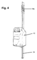
- FIG. 4 shows the view of a mounted on a mast 24 according to the invention container 10 with spatially separated solar module 19b.
Description
- Die Erfindung betrifft einen Behälter zur Aufnahme von hineingeworfenen Gegenständen mit einer im oberen Teil des Behälters angeordneten Einwurfsöffnung gemäss dem Oberbegriff des Anspruchs 1.
- Bisherige Behälter zur Aufnahme von hineingeworfenen Gegenständen, wie z.B. Müll- oder Wäscheeimer oder Briefkästen, haben den Nachteil, dass der Einwurf der jeweiligen Gegenstände nicht detektiert wird und die Person, die die Gegenstände einwirft, keine Rückmeldung über den ordnungsgemäßen Einwurf erhält.
- Die bisherigen Behältern bieten zudem keinen großen Anreiz zum Hineinwerfen von Gegenständen, da sie einerseits bei Dunkelheit nicht wahrgenommen werden und andererseits nach Einwurf keine Rückmeldung erfolgt und somit das Interesse der vorbeigehenden Person nicht geweckt wird. Gerade dieser ausbleibende "Belohnungseffekt" durch den aufnehmenden Behälter beim Einwurf von Gegenständen veranlasst viele Personen die Gegenstände gerade nicht in die vorgesehenen Behälter sondern einfach auf die Strasse zu werfen. Ein Behälter, der zur Interaktion" mit einer Person, die etwas einwirft, in der Lage ist, könnte einen Anreiz dazu bieten, diesen Behälter auch tatsächlich zu nutzen.
- So offenbart die
GB-A-2 321 518 - Ausgehend von diesem Stand der Technik ist es die Aufgabe der vorliegenden Erfindung, einen Behälter und ein Kit zum nachrüsten eines Behälters zur Verfügung zu stellen, der - gegebenfalls nach Installation des Kits - zur audiovisuellen Interaktion bei Annährung an den Behälter oder sein Nutzung geeignet ist.
- Gelöst wird diese Aufgabe durch ein Behälter mit der kennzeichenden Merkmalen des Anspruchs 1 und ein Kit zum nachrüsten eines Behälters nach Anspruch 21.
- Bei einem erfindungsgemäßen Behälter kann die integrierte Elektronik auch eine Datenverarbeitungseinrichtung sein, welche die akustischen und/oder visuellen Effekte, welche ausgegeben werden steuert. Des weiteren ist vorgesehen, dass die Datenverarbeitungseinrichtung mit Speichermodulen bestückt werden kann, auf denen Steueralgorithmen für den Behälter oder Audiosignale abgelegt sind.
- Die Lichtbänder (LISA ACRYLGLAS) können mit farblich unterschiedlichen Leuchtdioden ausgestattet sein, so dass unterschiedliche visuelle Eindrücke des Behälters erzeugt werden können, wobei die integrierte Elektronik die Steuerung vornimmt. An der Außenseite des Behälters können Sensoren, wie z.B. Bewegungsmelder, angebracht sein zur Aktivierung der Lichtbänder bei der Annährung einer Person an den Behälter.
- Der Behälter kann mit einer lichtleitenden Beschichtung, insbesondere einer Acrylglasbeschichtung, umschlossen und die lichtleitende Beschichtung kann mit den Lichtbändem direkt verbunden sein. Durch die direkte Verbindung wird das von den Lichtbändern ausgehende Licht in die lichtleitende Beschichtung geleitet und dort gestreut, so dass die Außenseite des Behälters mit dem erzeugten Streulicht vollständig beleuchtet wird. Dieses Streulicht kann genutzt werden um austauschbare, transparente Werbefolien, die auf dem Acrylglas angebracht sein können, zu beleuchten.
- Weiterhin kann das Audioausgabegerät, insbesondere ein Lautsprecher, Ton- und Sprachausgaben ausgeben, wobei das Audioausgabegerät so im Inneren des Behälters angeordnet ist, dass der so erzeugte Schall aus der Einwurföffnung direkt oder über Schallreflexionen austritt. Zusätzlich ist die integrierte Elektronik mit einer Radioantenne verbunden und über den Lautsprecher werden Radiosignale ausgegeben.
- Ebenfalls kann das Solarmodul wahlweise auf der Rückseite des Behälters und/oder bei einer Mastmontage des Behälters an einen Mast auf dem oberen Ende des Mast angeordnet sein.
- Bei der Spannungsquelle des erfindungsgemäßen Behälters handelt es sich vorzugsweise um einen Akku, der sowohl durch das Solarmodul als auch durch eine externe Spannungsquelle geladen wird. Der Ladevorgang kann durch eine Elektronik gesteuert werde, sodass eine Tiefentladung des Akkus verhindert wird. Durch dies Maßnahme wird die Lebensdauer des Akkus erheblich verlängert und die Betriebskosten des erfindungsgemäßen Behälters werden so verringert.
- In einer bevorzugten Ausführungsform der Erfindung handelt es sich bei dem Behälter um einen Papierkorb bzw. Mülleimer. Denkbar ist aber auch die Verwendung von Briefkästen oder Sicherheitsverwahrungsfächern, z.B. bei Banken im Außenbereich oder ähnlichen Einrichtungen.
- Die Rückseite des oberen Teils des Behälters, insbesondere eines im wesentlichen bekannten Mülleimers, ist angeschrägt, wobei die Winkellage der Schräge für eine optimale Sonnenlichtausbeute der an der Rückseite angeordneten Solarmodule ausgenutzt wird.
- Die Erfindung hat den Vorteil, insbesondere wenn es sich um einen Mülleimer handelt, dass durch die in den Mülleimer integrierte Elektronik hineingeworfene Gegenstände detektiert werden und als Reaktion auf die Detektion ein Signal ausgelöst wird, welches beispielsweise - aber nicht ausschließlich - in einem Blinken des Leuchtbandes und/oder einer Sprachausgabe und/oder Musikausgabe besteht. Auch ist über die erfindungsgemäße Mülltonne eine Werbebotschaft vermittelbar, z.B. durch Sprachausgabe oder aber durch die Mülltonne selbst, deren Ummantelung als (permanent oder teilweise) erleuchtete Werbefläche genutzt wird. Radioausgabe ist ebenso denkbar.
- Die in dem Mülleimer befindliche Elektronik ist mit einer Software/Hardware ausgestattet, die dazu geeignet ist, durch einfache dem Fachmann geläufige Handgriffe aktualisiert (update) zu werden (auch online oder mittels drahtloser Kommunikation). Auf diese Weise kann sehr einfach der Text oder die Musik- bzw. Werbebotschaft etc. aktualisiert werden und auch tagtäglichen Mitteilungsbotschaften (Nachrichten) angepasst werden. Die Elektronik kann dabei über Kabelstecker oder eine Datensende- und -empfangsanlage mit einem externen Rechner verbunden und Daten zwischen der Elektronik und dem externen Rechner ausgetauscht werden.
- Ein erfindungsgemäßer Behälter weist modulare Funktionseinheiten, nämlich Solarmodul, Sensor-Lampen-Modul und Elektronikmodul auf. Die gesamte Steuerung, Akku und Sprachmodule sind sicher in einem U-Profil aus Stahlblech eingebaut und bilden so dass Elektronikmodul, das auf dem Vierkantprofil zur Aufnahme der Zigarettenkippen, mit einer Sicherheitsschraube fixiert ist. Diese Schraube ist im Zigaretteneinwurf von vorne erreichbar. Viele der herkömmlichen Mülleimer weisen eine solche Sammeleinheit für Zigarettenkippen bereits auf, die im Inneren des Behälters angeordnet sind und bei dem die Einwurföffnung in der Einwurföffnung des Mülleimers angeordnet ist.
- Ein Update der Ton bzw. Lichteffekte ist durch Einstecken eines vorher programmierten Sprachmoduls - optional als Dienstleistung des Herstellers - mit Sprachchip, Verstärker und entsprechenden Steuerparametern möglich. Das Sprachmodul wird beispielsweise in Form einer 25-poligen Steckerleiste durch die Entleerungsklappe des Mülleimers von unten in das Elektronikmodul gesteckt, welches ja in dem U-Profil eingebaut ist.
- Das Solarmodul kann extern bzw. räumlich getrennt von dem Behälter an einem Aufstellmast oder einer Laterne mit Schellen befestigt sein. Durch diese erfindungsgemäße Maßnahme ist das Solarmodul sicher vor Vandalismus und es ist auch ein höherer Energieertrag zu erwarten. Die elektrische Zuleitung vom Solarmodul zu dem erfindungsgemäßen Behälter findet über kupferkaschiertes Folienkabel statt.
- Die Einheit bestehend aus Solarmodul, Sensor-Lampen-Modul und Elektronikmodul kann auch bei folgenden Anwendungen zum Einsatz kommen:
- als Schließfachsteuerung mit Beleuchtung im Außenbereich.
- als Briefkasten mit akustischer Werbefunktion, Beleuchtung und Display
- als Notrufsäule
- als Teil einer Überwachungsanlage
- Stadtinformationssystem, Leitsystem für Themen- und Vergnügungsparks.
- Der Einwurfsensor ist mit einem LED-Lampenstab zu einem Servicemodul auf einem Stahlblechwinkel montiert. Dieses Modul ist über eine Steckverbindung mit dem Elektronikmodul im U-Profil verbunden. Der Lautsprecher befindet sich im obersten Teil des U-Profils und damit in Höhe der Einwurföffnung. Der Sensor kann durch Einstellung auf Einwurf aber auch auf Passanten reagieren, d.h. sie ansprechen. Die Elektronik erlaubt die Einstellung beliebiger, beleuchtungsabhängiger Einschaltschwellen für die Funktionen Sprache (am Tag) und Licht (in der Nacht).
- Der Akku wird temperaturkompensiert vom Solarmodul geladen und vor Tiefentladung durch Lastabwurf geschützt. Eine externe Spannungsquelle kann zum Laden über Steckkontakt mit dem Akku verbunden werden. Der Tiefentladenschutz kann mittels Taster zur Funktionskontrolle der Elektronik deaktiviert werden.
- Bei den ausgegebenen Audiosignalen kann es sich um eine sogenannte Geräuschdusche, d.h. die Wiedergabe von Tonfrequenzen die den Umgebungslärm mit einer harmonischen Komponente überlagern und dadurch dämpfen, handeln. Des weiteren können per Mikrofon vorher aufgefangene akustische Signale wiedergegeben werden, welche Passanten als Quasi-Dialog oder Echofunktion erscheinen.
- Weiterhin kann vorgesehen sein, dass, sobald der maximale Füllstand eines erfindungsgemäßen Behälters, insbesondere eines Mülleimers, erreicht ist, sich die Bodenklappe öffnet und ein im Behälter befestigter PE-Sack mit dem Inhalt, z.B. Abfall, zu Boden fällt, womit sich das Fassungsvermögen des Behälters fast verdoppelt. Gleichzeitig kann ein Signal an die Zentrale gegeben und die Sprachausgabe: " Leider schon voll." aktiviert werden, bzw. das Licht aus- oder Blinklicht eingeschaltet werden.
- Eine zur Strasse gewandte IR-LED kann als Signalgeber für eine nötige, bzw. unnötige Leerung dienen, indem im anfahrenden Wartungsfahrzeug automatisch angezeigt wird, ob der Behälter voll oder leer ist. Dadurch werden die Stop-and-Go Intervalle der Wartungsfahrzeuge vermindert und Arbeitszeit gespart.
- Die Erfindung wird anhand von Ausführungsbeispielen und der nachfolgenden Figuren näher beschrieben; es zeigt:
- Fig. 1
- Gesamtansicht des erfindungsgemäßen Behälters;
- Fig. 2
- Schematische Darstellung eines erfindungsgemäßen Behälters mit Zigaretteneinwurf;
- Fig. 3
- Schnittzeichnung des oberen Teils der Behälters mit integrierter Elektronik und Detektionssensoren;
- Fig. 4
- Ansicht eines an einem Mast montierten erfindungsgemäßen Behälters mit räumlich getrenntem Solarmodul.
-
Figur 1 zeigt eine Gesamtansicht des erfindungsgemäßen Behälters 10. Um die Einwurfsöffnung 11 ist ein Lichtband 12a angeordnet. Ebenfalls ist um den Mittelteil des Behälters 10 ein Lichtband 12b angeordnet, das mit der den Behälter 10 umschließenden Acrylglasbeschichtung 13 direkt verbunden ist. Durch den direkten Kontakt zwischen dem Lichtband 12b und der Acrylglasbeschichtung 13 wird das Licht gestreut und beleuchtet den gesamten Behälter 10. Auf der abgeschrägten Rückseite 14 des oberen Teils des Behälters 10 ist ein Solarmodul (nicht dargestellt) angebracht und dient zur Stromversorgung einer im Behälter 10 integrierten Elektronik 15, sowie der angebrachten Ausgabegeräte. - In
Figur 2 ist ein erfindungsgemäßer Behälter schematisch dargestellt, der einen separaten Sammelbehälter für Zigaretten mit einer separaten Einwurföffnung 21 aufweist. Hinter dem Zigarettensammelbehälter 20 ist das Elektronikmodul 22 montiert, Die gestrichelten Linien zeigen den Verlauf des Zigarettensammelbehälters 20 und des Elektronikmoduls 22 im Inneren des Behälters 10 an. -
Fig. 3 zeigt eine Schnittzeichnung des oberen Teils der Behälters mit hinter dem Zigarettensammelbehälter 20 mittels einer Schraube befestigten Elektronikmodul 22 im Inneren des Behälters 10. Im Elektronikmodul 22 des Behälters 10 ist der Lautsprecher 18, die integrierte Elektronik 15 und die Spannungsversorgung 16 angeordnet. In der Einwurföffnung 11 befinden sich der Zigaretteneinwurf 21, der durch die Zigaretteneinwurfbeleuchtung 25 beleuchtet wird, die Bewegungssensoren 17 sowie das Einwurflichtband 12a. Auf der abgeschrägten Rückseite 14 des Behälters 10 ist das Solarmodul 19a angeordnet und durch eine Plexiglasabdeckung geschützt. Die Spannungsversorgung 16 sind herkömmliche Akkus (Bleigel, NiCd, NiMh oder Li-Ionen) und mit dem Solarmodul 19a verbunden. Weiterhin ist in der Einwurfsöffnung 11 ein Einwurflichtband 12a angebracht. -
Figur 4 zeigt die Ansicht eines an einem Mast 24 montierten erfindungsgemäßen Behälters 10 mit räumlich getrenntem Solarmodul 19b. -
- 10.
- Behälter
- 11.
- Einwurföffnung
- 12a.
- Einwurflichtband
- 12b.
- Behälterlichtband
- 13.
- lichtleitende Beschichtung
- 14.
- abgeschrägte Rückseite
- 15.
- Integrierte Elektronik
- 16.
- Spannungsversorgung
- 17.
- Bewegungssensor
- 18.
- Lautsprecher
- 19a.,
- 19b. Solarmodul
- 20.
- Zigarettensammelbehälter
- 21.
- Zigaretteneinwurf
- 22.
- Elektronikmodul
- 24.
- Mast
- 25.
- Zigaretteneinwurfbeleuchtung
Claims (23)
- Behälter (10) zur Aufnahme von hineingeworfenen Gegenständen mit einer im oberen Teil des Behälters (10) angeordneten Einwurföffnung (11), wobei im Inneren des Behälters (10) mindestens eine Lichtschranke den Einwurf eines Gegenstandes in den Behälter (10) delektiert und aufgrund der Detektion des eingeworfenen Gegenstandes durch eine integrierte Elektronik (15) Geräte (12a, 12b; 18) zur visuellen und/oder Audioausgabe von Signalen angesteuert werden, und innerhalb des Behälters (10) eine Spannungsquelle (16) zur, unter anderem, Stromversorgung der integrierten Elektronik (15) und der visuellen und/oder Audioausgabegeräten (12a, 12b; 18) angeordnet ist, und die Spannungsquelle (16) durch mindestens ein außerhalb des Behälters (10) angebrachtes Solarmodul (19a, 19b) mit Strom versorgt wird oder durch eine externe Spannungsquelle, dadurch gekennzeichnet, dass Bewegungssensoren (17) den Einwurf eines Gegenstandes in den Behälter (10) und/oder die Annäherung eines Passanten detektieren, dass in oder an dem Behälter (10) ein Mikrofon angeordnet ist, welches Ton- und/oder Sprachaufzeichnungen, die durch das Audioausgabegerät (18) abgegeben werden können, aufzeichnet, und dass ein um die Einwurföffnung (11) und/oder um den Behälter (10) angeordnetes Lichtband (12a,12b) als visuelles Ausgabegerät dient und permanent oder bei Annährung an den Behälter (10) oder beim Einwurf eines Gegenstandes durch die integrierte Elektronik (15) aktiviert und gesteuert wird.
- Behälter (10) nach Anspruch 1, bei dem die integrierte Elektronik (15) eine Datenverarbeitungseinrichtung ist.
- Behälter (10) nach Anspruch 1 oder 2, dadurch gekennzeichnet, dass das Lichtband (12a,12b) aus Leuchtdioden besteht.
- Behälter (10) nach Anspruch 3, dadurch gekennzeichnet, dass der Behälter (10) mit einer lichtleitenden Beschichtung (13), insbesondere einer Acrylglasbeschichtung, umschlossen ist, und dass die lichtleitende Beschichtung (13) mit den Lichtbändern (12a,12b) direkt verbunden sind.
- Behälter (10) nach Anspruch 4, welcher geeignete Befestigungsmittel aufweist, um austauschbare, transparente Werbefolien auf der lichtleitenden Beschichtung (13) aus Acrylglas anzubringen.
- Behälter (10) nach mindestens einem der Ansprüche 1 bis 5, dadurch gekennzeichnet, dass durch das Audioausgabegerät (18), insbesondere einen Lautsprecher, Ton- und Sprachausgaben ausgeben werden, wobei das Audioausgabegerät (18) so im Inneren des Behälters (10) angeordnet ist, dass der so erzeugte Schall aus der Einwurföffnung (11) direkt oder durch Schallreflexionen austritt.
- Behälter (10) nach mindestens einem der Ansprüche 1 bis 6, dadurch gekennzeichnet, dass die Audiosignale auf einem austauschbaren Sprachmodul abgespeichert sind.
- Behälter (10) nach mindestens einem der Ansprüche 1 bis 7, dadurch gekennzeichnet, dass an der Außenseite des Behälters (10) Sensoren, insbesondere Bewegungsmelder, zur Aktivierung der Lichtbänder (12a,12b) angeordnet sind.
- Behälter (10) nach mindestens einem der Ansprüche 1 bis 8, dadurch gekennzeichnet, dass die integrierte Elektronik (15) mit einer Radioantenne verbunden ist und über das Audioausgabegerät (18) Radiosignale ausgegeben werden.
- Behälter (10) nach mindestens einem der Ansprüche 1 bis 9, dadurch gekennzeichnet, dass das Solarmodul (19a, 19b) auf dem oberen Teil des Behälters (10) und/oder bei einer Mastmontage des Behälters (10) räumlich getrennt vom Behälter (10) auf dem oberen Ende des Mastes (24) angeordnet ist.
- Behälter (10) nach mindestens einem der Ansprüche 1 bis 10, dadurch gekennzeichnet, dass es sich bei der Spannungsquelle (16) um einen Akku handelt.
- Behälter (10) nach Anspruch 11, dadurch gekennzeichnet, dass das Solarmodul (19a, 19b) und/oder eine externe Spannungsquelle den Akku, der als Spannungsquelle (16) dient, auflädt.
- Behälter (10) nach Anspruch 14, dadurch gekennzeichnet, dass die integrierte Elektronik (15) eine Tiefentladung des Akkus verhindert.
- Behälter (10) nach mindestens einem der Ansprüche 1 bis 15, dadurch gekennzeichnet, dass die Rückseite (14) des oberen Teils des Behälterkopfteils abgeschrägt ist, wobei ein Winkel der Schräge für eine optimale Sonnenlichtausbeute der an der Rückseite (14) angeordneten Solarmodule (19a) gewählt ist.
- Behälter (10) nach mindestens einem der Ansprüche 1 bis 14, dadurch gekennzeichnet, dass die integrierte Elektronik (15) in einem Elektronikmodul (22) im Kopfteil des Behälters (10) oder auf einem U-Profil hinter einem im Behälter (10) befindlichen Zigarettensammelbehälter (20) angeordnet ist.
- Behälter (10) nach einem oder mehreren der vorhergehenden Ansprüche, dadurch gekennzeichnet, dass die integrierte Elektronik (15) mit einem Softwareprogramm verbunden ist, welches die visuelle- und/oder Audiosignalausgabe steuert.
- Behälter (10) nach einem oder mehreren der vorhergehenden Ansprüche, dadurch gekennzeichnet, dass die integrierte Elektronik (15) über Kabelstecker oder eine Datensende- und -empfangsanlage mit einem externen Rechner verbunden wird und Daten zwischen der integrierte Elektronik (15) und dem externen Rechner ausgetauscht werden.
- Behälter (10) nach Anspruch 17, dadurch gekennzeichnet, dass er über die Kabelstecker oder Datensende- und -empfangsanlage den Füllzustand des Behälters (10) anzeigt.
- Behälter (10) nach einem oder mehreren der vorhergehenden Ansprüche, dadurch gekennzeichnet, dass er über das Audio ausgabegerät (18), insbesondere einen Lautsprecher, spezielle Frequenzen wiedergibt, welche durch Überlagerung mit den Umgebungsgeräuschen des Behälters (10) die Umgebungsgeräusche dämpfen.
- Behälter (10) nach einem oder mehreren der vorhergehenden Ansprüche, dadurch gekennzeichnet, dass der Behälter (10) ein Mülleimer, ein Papierkorb, ein Briefkasten oder ein Sicherheitsverwahrungsfach ist.
- Kit zum Nachrüsten eines Behälters (10), wobei der Behälter (10) ein Mülleimer, ein Papierkorb, ein Briefkasten oder ein Sicherheitsverwahrungsfach ist, bestehend aus einem Sensor-Lampen-Modul (23), Elektronikmodul (22) und einem Solarmodul (19a, 19b), wobei das Sensor-Lampen-Modul (23) aus einem Bewegungssensor (17), einem Einwurflichtband (12a) und einem Behälterlichtband (12b) besteht, wobei ein um die Einwurföffnung (11) und/oder um den Behälter (10) angeordnetes Lichtband (12a,12b) als visuelles Ausgabegerät dient und permanent oder bei Annährung an den Behälter (10) oder beim Einwurf eines Gegenstandes durch die integrierte Elektronik (15) aktiviert und gesteuert wird, sowie aus geeigneten Befestigungsmitteln und optional einer Zigaretteneinwurfbeleuchtung (25) besteht.
- Kit nach Anspruch 21, dadurch gekennzeichnet, dass das Solarmodul (19a, 19b) aus einer extern oder auf einer abgeschrägten (14) Rückseite (14) des oberen Teils des Behälterkopfteils anzubringenden Solarzelle, einem kupferkaschierten Folienkabel sowie geeigneten Befestigungsmitteln besteht.
- Kit nach Anspruch 21, dadurch gekennzeichnet, dass das Elektronikmodul (22) aus einer Elektronik (15) zur Steuerung, einer Spannungsquelle (16), Lautsprecher (18) sowie einem Träger und geeigneten Befestigungsmitteln besteht.
Applications Claiming Priority (5)
| Application Number | Priority Date | Filing Date | Title |
|---|---|---|---|
| DE20217842U | 2002-11-19 | ||
| DE20217842 | 2002-11-19 | ||
| DE2003205134 DE20305134U1 (de) | 2002-11-19 | 2003-03-31 | Interaktiver Aufnahmebehälter |
| DE20305134U | 2003-03-31 | ||
| PCT/DE2003/003865 WO2004045992A2 (de) | 2002-11-19 | 2003-11-19 | Interaktiver aufnahmebehälter |
Publications (2)
| Publication Number | Publication Date |
|---|---|
| EP1562844A2 EP1562844A2 (de) | 2005-08-17 |
| EP1562844B1 true EP1562844B1 (de) | 2008-04-23 |
Family
ID=32070902
Family Applications (1)
| Application Number | Title | Priority Date | Filing Date |
|---|---|---|---|
| EP03788805A Expired - Lifetime EP1562844B1 (de) | 2002-11-19 | 2003-11-19 | Interaktiver aufnahmebehälter |
Country Status (4)
| Country | Link |
|---|---|
| EP (1) | EP1562844B1 (de) |
| AT (1) | ATE393106T1 (de) |
| DE (3) | DE10394076D2 (de) |
| WO (1) | WO2004045992A2 (de) |
Cited By (2)
| Publication number | Priority date | Publication date | Assignee | Title |
|---|---|---|---|---|
| EP2803953A1 (de) | 2013-05-16 | 2014-11-19 | Robert Bosch Gmbh | Abfallbehältnis mit Sensoranordnung und Verfahren zum Überwachen eines Abfallbehältnisses |
| DE102022120553A1 (de) | 2022-08-15 | 2024-02-15 | Framo Morat GmbH & Co. KG | Vorrichtung zur Überwachung eines Getränks |
Families Citing this family (11)
| Publication number | Priority date | Publication date | Assignee | Title |
|---|---|---|---|---|
| US20080067227A1 (en) | 2003-06-09 | 2008-03-20 | Poss James A | Eletrically-powered programmable package deposit enclosure |
| WO2010142324A1 (en) * | 2009-06-09 | 2010-12-16 | Sca Hygiene Products Ab | Dispensing system and method for dispensing a product |
| EP2325109B1 (de) * | 2009-11-18 | 2017-02-01 | ESE World B.V. | Müllbehälter |
| EP2598410A4 (de) * | 2010-07-28 | 2014-12-24 | Big Belly Solar Inc | Elektrisch betriebener programmierbarer abfallbehälter |
| WO2013069029A1 (en) * | 2011-11-08 | 2013-05-16 | Hera S.P.A. | Kit for monitoring the quantity of material introduced in a container and container provided with such a kit |
| DE102013112146A1 (de) | 2013-11-05 | 2015-05-07 | Klaus Kremer | Autonomes System zur Erfassung von Abfällen |
| DE202013104949U1 (de) | 2013-11-05 | 2014-01-20 | Klaus Kremer | Autonomes System zur Erfassung von Abfällen |
| WO2017175244A1 (en) * | 2016-04-06 | 2017-10-12 | Srivastava Chitransh | A smart bin |
| ITUA20163835A1 (it) * | 2016-05-26 | 2017-11-26 | Gb Gest S R L | Apparato di controllo dello stato funzionale di un contenitore per rifiuti, e contenitore per rifiuti comprendente detto apparato |
| DE102016213172A1 (de) * | 2016-07-19 | 2018-01-25 | BSH Hausgeräte GmbH | Einkaufssystem |
| CN106742914A (zh) * | 2017-02-27 | 2017-05-31 | 深圳市赛亿科技开发有限公司 | 一种带灯的垃圾桶 |
Family Cites Families (7)
| Publication number | Priority date | Publication date | Assignee | Title |
|---|---|---|---|---|
| GB2261096A (en) * | 1991-10-16 | 1993-05-05 | Prior Consulting Limited | Waste receptacle |
| DE4336334C1 (de) * | 1993-10-25 | 1994-11-24 | Deutsche Aerospace | Computergesteuerter Recycling-Sammelbehälter |
| US5532680A (en) * | 1995-03-27 | 1996-07-02 | Ousborne; Jeffrey | Automatic message playback system |
| GB9701255D0 (en) * | 1997-01-22 | 1997-03-12 | Docherty John H | Refuse receptacle |
| WO2000055833A1 (en) * | 1999-03-16 | 2000-09-21 | Angel, Chiriboga, C. | Combined advertising display and trash receptacle business system |
| KR20020019300A (ko) * | 2000-09-05 | 2002-03-12 | 김용곤 | 디스플레이 기능을 갖는 재활용품 분리수거기 |
| DE20305134U1 (de) * | 2002-11-19 | 2003-07-24 | Fiedler Sepp | Interaktiver Aufnahmebehälter |
-
2003
- 2003-11-19 DE DE10394076T patent/DE10394076D2/de not_active Expired - Fee Related
- 2003-11-19 DE DE50309709T patent/DE50309709D1/de not_active Expired - Lifetime
- 2003-11-19 EP EP03788805A patent/EP1562844B1/de not_active Expired - Lifetime
- 2003-11-19 WO PCT/DE2003/003865 patent/WO2004045992A2/de active IP Right Grant
- 2003-11-19 DE DE20318149U patent/DE20318149U1/de not_active Expired - Lifetime
- 2003-11-19 AT AT03788805T patent/ATE393106T1/de not_active IP Right Cessation
Cited By (3)
| Publication number | Priority date | Publication date | Assignee | Title |
|---|---|---|---|---|
| EP2803953A1 (de) | 2013-05-16 | 2014-11-19 | Robert Bosch Gmbh | Abfallbehältnis mit Sensoranordnung und Verfahren zum Überwachen eines Abfallbehältnisses |
| DE102013209075A1 (de) | 2013-05-16 | 2014-11-20 | Robert Bosch Gmbh | Abfallbehältnis mit Sensoranordnung und Verfahren zum Überwachen eines Abfallbehältnisses |
| DE102022120553A1 (de) | 2022-08-15 | 2024-02-15 | Framo Morat GmbH & Co. KG | Vorrichtung zur Überwachung eines Getränks |
Also Published As
| Publication number | Publication date |
|---|---|
| WO2004045992A2 (de) | 2004-06-03 |
| DE20318149U1 (de) | 2004-03-25 |
| ATE393106T1 (de) | 2008-05-15 |
| DE10394076D2 (de) | 2005-09-29 |
| DE50309709D1 (de) | 2008-06-05 |
| EP1562844A2 (de) | 2005-08-17 |
| WO2004045992A3 (de) | 2004-08-12 |
Similar Documents
| Publication | Publication Date | Title |
|---|---|---|
| EP1562844B1 (de) | Interaktiver aufnahmebehälter | |
| WO2010022906A2 (de) | Identifikationselement mit einem optischen transponder | |
| WO1995017741A1 (de) | Werbeschaukasten mit integriertem kleinabfallbehälter | |
| CN201494853U (zh) | 多功能垃圾箱 | |
| CN109335414A (zh) | 一种智能垃圾箱系统及其使用方法 | |
| DE202006003450U1 (de) | Müllerkennungssystem | |
| CN106044006A (zh) | 一种多功能垃圾箱 | |
| CN206634559U (zh) | 一种能显示垃圾装载率的太阳能智能垃圾桶 | |
| CN113353486A (zh) | 一种自动垃圾分类回收箱 | |
| DE102014118877B4 (de) | Behälter zur Sammlung von Wertstoffen und System mit mehreren solchen Behältern | |
| DE4430936A1 (de) | Überdachte Entsorgungs-Station zur Abfalltrennung | |
| WO2017063013A1 (de) | Signalleuchte | |
| EP1754203B1 (de) | Vorrichtung für die Ausgabe eines Informationsträgers | |
| CN201647510U (zh) | 一种环保广告垃圾箱 | |
| GB2415886A (en) | A recycling unit with advertising displays | |
| DE4022124A1 (de) | Altglas-, blech- und altpapier-entsorgungssystem fuer wiederaufbereitung und wiederverwertung von rohstoffen | |
| CN212449013U (zh) | 一种垃圾分类系统 | |
| CN107472746A (zh) | 一种用于固体垃圾分类的设备 | |
| DE3927212C2 (de) | ||
| DE102020210780A1 (de) | Ladestation zum Laden elektrisch betriebener Fahrzeuge | |
| CN205771186U (zh) | 一种带物品回收功能的广告柜 | |
| CN106516503A (zh) | 一种垃圾桶 | |
| CN205574781U (zh) | 一种太阳能垃圾桶 | |
| CN213518433U (zh) | 一种智能募捐公益平台 | |
| CN207450856U (zh) | 一种室外快递派送设施 |
Legal Events
| Date | Code | Title | Description |
|---|---|---|---|
| PUAI | Public reference made under article 153(3) epc to a published international application that has entered the european phase |
Free format text: ORIGINAL CODE: 0009012 |
|
| 17P | Request for examination filed |
Effective date: 20050610 |
|
| AK | Designated contracting states |
Kind code of ref document: A2 Designated state(s): AT BE BG CH CY CZ DE DK EE ES FI FR GB GR HU IE IT LI LU MC NL PT RO SE SI SK TR |
|
| AX | Request for extension of the european patent |
Extension state: AL LT LV MK |
|
| DAX | Request for extension of the european patent (deleted) | ||
| 17Q | First examination report despatched |
Effective date: 20060303 |
|
| GRAP | Despatch of communication of intention to grant a patent |
Free format text: ORIGINAL CODE: EPIDOSNIGR1 |
|
| GRAS | Grant fee paid |
Free format text: ORIGINAL CODE: EPIDOSNIGR3 |
|
| GRAA | (expected) grant |
Free format text: ORIGINAL CODE: 0009210 |
|
| AK | Designated contracting states |
Kind code of ref document: B1 Designated state(s): AT BE BG CH CY CZ DE DK EE ES FI FR GB GR HU IE IT LI LU MC NL PT RO SE SI SK TR |
|
| REG | Reference to a national code |
Ref country code: GB Ref legal event code: FG4D Free format text: NOT ENGLISH |
|
| REG | Reference to a national code |
Ref country code: CH Ref legal event code: EP |
|
| REF | Corresponds to: |
Ref document number: 50309709 Country of ref document: DE Date of ref document: 20080605 Kind code of ref document: P |
|
| REG | Reference to a national code |
Ref country code: IE Ref legal event code: FG4D Free format text: LANGUAGE OF EP DOCUMENT: GERMAN |
|
| REG | Reference to a national code |
Ref country code: CH Ref legal event code: NV Representative=s name: KELLER & PARTNER PATENTANWAELTE AG |
|
| PG25 | Lapsed in a contracting state [announced via postgrant information from national office to epo] |
Ref country code: SI Free format text: LAPSE BECAUSE OF FAILURE TO SUBMIT A TRANSLATION OF THE DESCRIPTION OR TO PAY THE FEE WITHIN THE PRESCRIBED TIME-LIMIT Effective date: 20080423 |
|
| NLV1 | Nl: lapsed or annulled due to failure to fulfill the requirements of art. 29p and 29m of the patents act | ||
| PG25 | Lapsed in a contracting state [announced via postgrant information from national office to epo] |
Ref country code: PT Free format text: LAPSE BECAUSE OF FAILURE TO SUBMIT A TRANSLATION OF THE DESCRIPTION OR TO PAY THE FEE WITHIN THE PRESCRIBED TIME-LIMIT Effective date: 20080923 Ref country code: FI Free format text: LAPSE BECAUSE OF FAILURE TO SUBMIT A TRANSLATION OF THE DESCRIPTION OR TO PAY THE FEE WITHIN THE PRESCRIBED TIME-LIMIT Effective date: 20080423 Ref country code: NL Free format text: LAPSE BECAUSE OF FAILURE TO SUBMIT A TRANSLATION OF THE DESCRIPTION OR TO PAY THE FEE WITHIN THE PRESCRIBED TIME-LIMIT Effective date: 20080423 Ref country code: BG Free format text: LAPSE BECAUSE OF FAILURE TO SUBMIT A TRANSLATION OF THE DESCRIPTION OR TO PAY THE FEE WITHIN THE PRESCRIBED TIME-LIMIT Effective date: 20080723 Ref country code: ES Free format text: LAPSE BECAUSE OF FAILURE TO SUBMIT A TRANSLATION OF THE DESCRIPTION OR TO PAY THE FEE WITHIN THE PRESCRIBED TIME-LIMIT Effective date: 20080803 |
|
| ET | Fr: translation filed | ||
| PG25 | Lapsed in a contracting state [announced via postgrant information from national office to epo] |
Ref country code: DK Free format text: LAPSE BECAUSE OF FAILURE TO SUBMIT A TRANSLATION OF THE DESCRIPTION OR TO PAY THE FEE WITHIN THE PRESCRIBED TIME-LIMIT Effective date: 20080423 Ref country code: CZ Free format text: LAPSE BECAUSE OF FAILURE TO SUBMIT A TRANSLATION OF THE DESCRIPTION OR TO PAY THE FEE WITHIN THE PRESCRIBED TIME-LIMIT Effective date: 20080423 Ref country code: SE Free format text: LAPSE BECAUSE OF FAILURE TO SUBMIT A TRANSLATION OF THE DESCRIPTION OR TO PAY THE FEE WITHIN THE PRESCRIBED TIME-LIMIT Effective date: 20080723 |
|
| PGFP | Annual fee paid to national office [announced via postgrant information from national office to epo] |
Ref country code: CH Payment date: 20081017 Year of fee payment: 6 Ref country code: IE Payment date: 20081112 Year of fee payment: 6 Ref country code: LU Payment date: 20081016 Year of fee payment: 6 |
|
| PG25 | Lapsed in a contracting state [announced via postgrant information from national office to epo] |
Ref country code: SK Free format text: LAPSE BECAUSE OF FAILURE TO SUBMIT A TRANSLATION OF THE DESCRIPTION OR TO PAY THE FEE WITHIN THE PRESCRIBED TIME-LIMIT Effective date: 20080423 Ref country code: RO Free format text: LAPSE BECAUSE OF FAILURE TO SUBMIT A TRANSLATION OF THE DESCRIPTION OR TO PAY THE FEE WITHIN THE PRESCRIBED TIME-LIMIT Effective date: 20080423 |
|
| PGFP | Annual fee paid to national office [announced via postgrant information from national office to epo] |
Ref country code: AT Payment date: 20081104 Year of fee payment: 6 Ref country code: BE Payment date: 20080915 Year of fee payment: 6 |
|
| PLBE | No opposition filed within time limit |
Free format text: ORIGINAL CODE: 0009261 |
|
| STAA | Information on the status of an ep patent application or granted ep patent |
Free format text: STATUS: NO OPPOSITION FILED WITHIN TIME LIMIT |
|
| 26N | No opposition filed |
Effective date: 20090126 |
|
| PG25 | Lapsed in a contracting state [announced via postgrant information from national office to epo] |
Ref country code: EE Free format text: LAPSE BECAUSE OF FAILURE TO SUBMIT A TRANSLATION OF THE DESCRIPTION OR TO PAY THE FEE WITHIN THE PRESCRIBED TIME-LIMIT Effective date: 20080423 |
|
| PGFP | Annual fee paid to national office [announced via postgrant information from national office to epo] |
Ref country code: FR Payment date: 20080918 Year of fee payment: 6 |
|
| PG25 | Lapsed in a contracting state [announced via postgrant information from national office to epo] |
Ref country code: MC Free format text: LAPSE BECAUSE OF NON-PAYMENT OF DUE FEES Effective date: 20081130 |
|
| PGFP | Annual fee paid to national office [announced via postgrant information from national office to epo] |
Ref country code: GB Payment date: 20081119 Year of fee payment: 6 |
|
| PG25 | Lapsed in a contracting state [announced via postgrant information from national office to epo] |
Ref country code: IT Free format text: LAPSE BECAUSE OF FAILURE TO SUBMIT A TRANSLATION OF THE DESCRIPTION OR TO PAY THE FEE WITHIN THE PRESCRIBED TIME-LIMIT Effective date: 20080423 |
|
| BERE | Be: lapsed |
Owner name: SCHMIDT, HARTMUT Effective date: 20091130 Owner name: FIEDLER, SEPP Effective date: 20091130 |
|
| REG | Reference to a national code |
Ref country code: CH Ref legal event code: PL |
|
| GBPC | Gb: european patent ceased through non-payment of renewal fee |
Effective date: 20091119 |
|
| PG25 | Lapsed in a contracting state [announced via postgrant information from national office to epo] |
Ref country code: CY Free format text: LAPSE BECAUSE OF FAILURE TO SUBMIT A TRANSLATION OF THE DESCRIPTION OR TO PAY THE FEE WITHIN THE PRESCRIBED TIME-LIMIT Effective date: 20080423 Ref country code: HU Free format text: LAPSE BECAUSE OF FAILURE TO SUBMIT A TRANSLATION OF THE DESCRIPTION OR TO PAY THE FEE WITHIN THE PRESCRIBED TIME-LIMIT Effective date: 20081024 |
|
| REG | Reference to a national code |
Ref country code: IE Ref legal event code: MM4A |
|
| REG | Reference to a national code |
Ref country code: FR Ref legal event code: ST Effective date: 20100730 |
|
| PG25 | Lapsed in a contracting state [announced via postgrant information from national office to epo] |
Ref country code: AT Free format text: LAPSE BECAUSE OF NON-PAYMENT OF DUE FEES Effective date: 20091119 Ref country code: TR Free format text: LAPSE BECAUSE OF FAILURE TO SUBMIT A TRANSLATION OF THE DESCRIPTION OR TO PAY THE FEE WITHIN THE PRESCRIBED TIME-LIMIT Effective date: 20080423 |
|
| PG25 | Lapsed in a contracting state [announced via postgrant information from national office to epo] |
Ref country code: BE Free format text: LAPSE BECAUSE OF NON-PAYMENT OF DUE FEES Effective date: 20091130 Ref country code: CH Free format text: LAPSE BECAUSE OF NON-PAYMENT OF DUE FEES Effective date: 20091130 Ref country code: FR Free format text: LAPSE BECAUSE OF NON-PAYMENT OF DUE FEES Effective date: 20091130 Ref country code: GR Free format text: LAPSE BECAUSE OF FAILURE TO SUBMIT A TRANSLATION OF THE DESCRIPTION OR TO PAY THE FEE WITHIN THE PRESCRIBED TIME-LIMIT Effective date: 20080724 Ref country code: IE Free format text: LAPSE BECAUSE OF NON-PAYMENT OF DUE FEES Effective date: 20091119 Ref country code: LI Free format text: LAPSE BECAUSE OF NON-PAYMENT OF DUE FEES Effective date: 20091130 |
|
| PG25 | Lapsed in a contracting state [announced via postgrant information from national office to epo] |
Ref country code: GB Free format text: LAPSE BECAUSE OF NON-PAYMENT OF DUE FEES Effective date: 20091119 |
|
| PGFP | Annual fee paid to national office [announced via postgrant information from national office to epo] |
Ref country code: DE Payment date: 20101109 Year of fee payment: 8 |
|
| PG25 | Lapsed in a contracting state [announced via postgrant information from national office to epo] |
Ref country code: LU Free format text: LAPSE BECAUSE OF NON-PAYMENT OF DUE FEES Effective date: 20091119 |
|
| REG | Reference to a national code |
Ref country code: DE Ref legal event code: R119 Ref document number: 50309709 Country of ref document: DE Effective date: 20120601 |
|
| PG25 | Lapsed in a contracting state [announced via postgrant information from national office to epo] |
Ref country code: DE Free format text: LAPSE BECAUSE OF NON-PAYMENT OF DUE FEES Effective date: 20120601 |