EP1562015A2 - Wärmetauscherblock - Google Patents
Wärmetauscherblock Download PDFInfo
- Publication number
- EP1562015A2 EP1562015A2 EP05290235A EP05290235A EP1562015A2 EP 1562015 A2 EP1562015 A2 EP 1562015A2 EP 05290235 A EP05290235 A EP 05290235A EP 05290235 A EP05290235 A EP 05290235A EP 1562015 A2 EP1562015 A2 EP 1562015A2
- Authority
- EP
- European Patent Office
- Prior art keywords
- tubes
- tube
- insert
- heat exchanger
- core structure
- Prior art date
- Legal status (The legal status is an assumption and is not a legal conclusion. Google has not performed a legal analysis and makes no representation as to the accuracy of the status listed.)
- Withdrawn
Links
- 239000002826 coolant Substances 0.000 claims abstract description 32
- 230000002787 reinforcement Effects 0.000 claims abstract description 11
- 238000003780 insertion Methods 0.000 claims abstract description 6
- 230000037431 insertion Effects 0.000 claims abstract description 6
- 230000015556 catabolic process Effects 0.000 description 4
- 238000006731 degradation reaction Methods 0.000 description 4
- 230000008646 thermal stress Effects 0.000 description 4
- 239000012141 concentrate Substances 0.000 description 3
- XAGFODPZIPBFFR-UHFFFAOYSA-N aluminium Chemical compound [Al] XAGFODPZIPBFFR-UHFFFAOYSA-N 0.000 description 2
- 229910052782 aluminium Inorganic materials 0.000 description 2
- 238000010438 heat treatment Methods 0.000 description 2
- 238000012986 modification Methods 0.000 description 2
- 230000004048 modification Effects 0.000 description 2
- 238000005452 bending Methods 0.000 description 1
- 238000010276 construction Methods 0.000 description 1
- 238000001816 cooling Methods 0.000 description 1
- 238000004519 manufacturing process Methods 0.000 description 1
- 238000000034 method Methods 0.000 description 1
- 239000011347 resin Substances 0.000 description 1
- 229920005989 resin Polymers 0.000 description 1
Images




Classifications
-
- F—MECHANICAL ENGINEERING; LIGHTING; HEATING; WEAPONS; BLASTING
- F28—HEAT EXCHANGE IN GENERAL
- F28F—DETAILS OF HEAT-EXCHANGE AND HEAT-TRANSFER APPARATUS, OF GENERAL APPLICATION
- F28F3/00—Plate-like or laminated elements; Assemblies of plate-like or laminated elements
- F28F3/02—Elements or assemblies thereof with means for increasing heat-transfer area, e.g. with fins, with recesses, with corrugations
- F28F3/025—Elements or assemblies thereof with means for increasing heat-transfer area, e.g. with fins, with recesses, with corrugations the means being corrugated, plate-like elements
-
- F—MECHANICAL ENGINEERING; LIGHTING; HEATING; WEAPONS; BLASTING
- F28—HEAT EXCHANGE IN GENERAL
- F28D—HEAT-EXCHANGE APPARATUS, NOT PROVIDED FOR IN ANOTHER SUBCLASS, IN WHICH THE HEAT-EXCHANGE MEDIA DO NOT COME INTO DIRECT CONTACT
- F28D1/00—Heat-exchange apparatus having stationary conduit assemblies for one heat-exchange medium only, the media being in contact with different sides of the conduit wall, in which the other heat-exchange medium is a large body of fluid, e.g. domestic or motor car radiators
- F28D1/02—Heat-exchange apparatus having stationary conduit assemblies for one heat-exchange medium only, the media being in contact with different sides of the conduit wall, in which the other heat-exchange medium is a large body of fluid, e.g. domestic or motor car radiators with heat-exchange conduits immersed in the body of fluid
- F28D1/04—Heat-exchange apparatus having stationary conduit assemblies for one heat-exchange medium only, the media being in contact with different sides of the conduit wall, in which the other heat-exchange medium is a large body of fluid, e.g. domestic or motor car radiators with heat-exchange conduits immersed in the body of fluid with tubular conduits
- F28D1/053—Heat-exchange apparatus having stationary conduit assemblies for one heat-exchange medium only, the media being in contact with different sides of the conduit wall, in which the other heat-exchange medium is a large body of fluid, e.g. domestic or motor car radiators with heat-exchange conduits immersed in the body of fluid with tubular conduits the conduits being straight
- F28D1/0535—Heat-exchange apparatus having stationary conduit assemblies for one heat-exchange medium only, the media being in contact with different sides of the conduit wall, in which the other heat-exchange medium is a large body of fluid, e.g. domestic or motor car radiators with heat-exchange conduits immersed in the body of fluid with tubular conduits the conduits being straight the conduits having a non-circular cross-section
- F28D1/05366—Assemblies of conduits connected to common headers, e.g. core type radiators
-
- F—MECHANICAL ENGINEERING; LIGHTING; HEATING; WEAPONS; BLASTING
- F28—HEAT EXCHANGE IN GENERAL
- F28F—DETAILS OF HEAT-EXCHANGE AND HEAT-TRANSFER APPARATUS, OF GENERAL APPLICATION
- F28F19/00—Preventing the formation of deposits or corrosion, e.g. by using filters or scrapers
- F28F19/002—Preventing the formation of deposits or corrosion, e.g. by using filters or scrapers by using inserts or attachments
-
- F—MECHANICAL ENGINEERING; LIGHTING; HEATING; WEAPONS; BLASTING
- F28—HEAT EXCHANGE IN GENERAL
- F28F—DETAILS OF HEAT-EXCHANGE AND HEAT-TRANSFER APPARATUS, OF GENERAL APPLICATION
- F28F2225/00—Reinforcing means
- F28F2225/04—Reinforcing means for conduits
-
- Y—GENERAL TAGGING OF NEW TECHNOLOGICAL DEVELOPMENTS; GENERAL TAGGING OF CROSS-SECTIONAL TECHNOLOGIES SPANNING OVER SEVERAL SECTIONS OF THE IPC; TECHNICAL SUBJECTS COVERED BY FORMER USPC CROSS-REFERENCE ART COLLECTIONS [XRACs] AND DIGESTS
- Y10—TECHNICAL SUBJECTS COVERED BY FORMER USPC
- Y10S—TECHNICAL SUBJECTS COVERED BY FORMER USPC CROSS-REFERENCE ART COLLECTIONS [XRACs] AND DIGESTS
- Y10S165/00—Heat exchange
- Y10S165/906—Reinforcement
Definitions
- the present invention relates to a core structure of a heat exchanger that includes tubes and corrugated fins arranged alternatively between the seat plates connected by reinforcements.
- a core structure of a heat exchanger of this kind is disclosed in Japanese patent laying-open publication No. (Hei) 11 - 14285.
- This core structure of the heat exchanger is constructed so that tubes and corrugated fins are alternately arranged between seat plates and both edge portions are coupled and reinforced by reinforcements.
- FIG. 10 Another conventional core structure of a heat exchanger is disclosed in Japanese utility model laying-open publication No. (Hei) 02 - 54076.
- This core structure of the heat structure is used for hybrid electric vehicles or the like, and has the core structure similar to the above conventional one, while it has two tanks attached to seat plates and two core parts for cooling coolants with different temperature or different kind of coolant.
- the rapid changes in temperature hardly occur, while rapid change of coolant flowing an engine into a radiator in temperature from low to high occurs, for example, in a case that when the engine is started in a cold region, coolant of the engine increases gradually in temperature but does not flow into the radiator until it reaches a valve-opening temperature of a thermostat, and then the temperature of the coolant becomes high to cause a valve of the thermostat to open, so that the coolant of high temperature flows into the radiator for the first time, or in a case of hunting phenomena such that the thermostat repeats opening and closing.
- the tubes arranged at the outermost positions of the seat plates are restricted in their thermal expansions in the thickness direction by the reinforcements, thermal stresses due to the differences between the thermal expansion amounts of the tubes, the reinforcements, and the seat plates concentrate on seat-plate contacting portions of the outermost positioned tubes to cause the contacting portions to crack.
- the heat exchanger used in a hybrid electric vehicle or the like has the tubes that are arranged at outermost positions of the two core parts, and especially adjacent tubes of the core parts are applied by strong thermal stress to be cracked because of coolants with different temperatures flowing in the tubes.
- an object of the present invention to provide a core structure of a heat exchanger which overcomes the foregoing drawbacks and can avoid occurrence of a crack in a seat-plate contacting portion of a tube arranged at an outermost position of the seat plate without degradation of heat exchanging performance and enlargement of dimensions of a heat exchanger.
- a core structure of a heat exchanger comprising: seat plates arranged opposite to each other with a predetermined space interposed therebetween, the seat plates being formed with tube holes; reinforcements connecting the seat plates at end portions thereof; tubes fixed at both end portions thereof by insertion into the tube holes; corrugated fins arranged between the tubes; and an upper and lower tanks attached to the seat plates, tanks being connected by the tubes so that coolant can flow between the tanks through the tubes, wherein the tubes and the corrugated fins are alternatively arranged to form a core part, and a tube arranged in at least an outermost position of the core part among the tube being inserted at end portions thereof by insert members so that the insert members increase rigidity of the end positions of the tube inserted by the insert members and ensure flowing of the coolant between the tanks through the tube inserted by the insert members.
- the insert members are inserted in the edge portions of the tube and increase rigidity of the tube, so that a crack does not cause in the tube even when thermal stress concentrates on a seat-plate contacting portion of the tube due to rapidly repeated change of the coolant in temperature, resulting in an improvement in durability of the core structure of the heat exchanger.
- the insert members ensure the flowing between the tanks through the tube even when the insert members are inserted in the tube, which can avoid degradation of heat exchanging performance and enlargement of dimensions of a heat exchanger.
- the insert members include two insert portions to be inserted in the tube and a connecting portion that connects the insert portions with each other in a state that a space formed between the insert portions can flow the coolant between an inside of the tube and an inside of the tank through the space when the insert member is inserted in the tube.
- the insert portions coupled by the connecting portion can reinforce the tube from its inside to increase its rigidity, ensuring to avoid occurrence of a crack in the tube with a simple structure and low manufacturing cost.
- the connecting portion is positioned out of the tube, and the insert portions being bent toward an edge side of the seat plate so that the connecting portion is dislocated from an overhead of opening of the tube.
- the coolant can pass through the insert members with suppressing the lowering of its current speed at a low level, resulting in maintaining the heat exchanging performance.
- the connecting portion has an opening to pass the coolant.
- the coolant can pass also through the opening, improving the flow through the insert members.
- the insert portions have a stopper portion to determine an insert length of the insert portions in the tube by contact of the stopper portion and the tube.
- the insert members can be inserted in the tube and easily stopped at their proper positions.
- the tube includes tubes adjacent to each other that belong to adjacent different core parts of the heat exchanger and are arranged at adjacent outermost positions of the core parts.
- FIGS. 1 and 2 of the drawings there is shown a first preferred embodiment of a core structure of a heat exchanger according to the present invention.
- FIG 1 shows an entire front view partly in section of the core structure of the heat exchanger
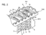
- FIG. 2 shows an upper portion of an upper seat plate in an upper tank, which are used in the core structure shown in FIG. 1.
- the core structure includes an upper and lower seat plates 3 and 4, a pair of tanks 1 and 2 attached to the seat plates 3 and 4 respectively, reinforcements connecting the seat plates 3 and 4, tubes 5, 5a, and 5b, and corrugated fins 6.
- the upper seat plate 3 and the lower seat plate 4 have plural tube holes 12 to fix the tubes 5, 5a, and 5b by insertion of the tubes 5, 5a, and 5b in the tube holes 12.
- the upper and lower seat plates 3 and 4 are connected by the reinforcements 7 and 8 at their end portions, respectively.
- the tubes 5, 5a, and 5b and the corrugated fins 6 are alternatively arranged between the reinforcements 7 and 8 to form a core part.
- the tubes 5, 5a, and 5b have holes to flow coolant from the upper tank 1 to the lower tank 2, and tubes 5a and 5b arranged at outermost positions of the core part are inserted by insert members 9, which will be described in detail later.
- the seat plates 3 and 4 are made of aluminum, and assembled in advance and then brazed in a heat treatment furnace, not shown.
- the upper and lower tanks 1 and 2 made of resin, are attached to the upper and lower seat plates 3 and 4, respectively, while the core part and the tanks 1 and 2 are brazed in a heat treatment furnace when the tanks 1 and 2 are made of aluminum.
- the insert members 9 are formed to have two insert portions 9a and 9b, and a connecting portion 9c that connects the insert portions 9a and 9b at their end portions.
- the insert portions 9a and 9b are set in length to extend deeper than the positions of seat-plate contacting portion 10 of the tube 5a as shown in FIG 6 when the insert members 9 are inserted in the tubes 5a and 5b.
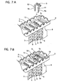
- FIG 7A shows a state of the insert members 9 and tube 5a before the insertion
- FIG 7B shows a state of them after the insertion.
- the insert portions 9a and 9b are insertable in the holes of the tubes 5, 5a, and 5b to contact with an inner side of the hole, and are formed to have a tapered shape at their inserting edge portions for easy inserting.
- the insert portions 9a and 9b are provided with topper portions S1 and S2 to contact with the edge portions 5c of the tube 5, 5a, and 5b and determine an insert length in the hole.
- the insert portions 9a and 9b are bent at their intermediate portions, as shown especially in FIGS. 3 and 4, so that a space O through which the coolant can flow is formed between the insert portions 9a and 9b as shown in FIGS. 3 and 5 and so that the connecting portion 9c is dislocated from the overhead of the hole of tube 5a or 5b as shown in FIG 5.
- the connecting portion 9c is formed with an opening 11 to pass the coolant, which improves the flow of the coolant in the tanks 1 and 2.
- the insert members 9 can be assembled by either a manual procedure with using clipping tool of the connecting portions 9c or an automatic assembly machine.
- the core structure of the heat exchanger of the first embodiment has the following advantages.
- the inset members 9 have insert portions 9a and 9b inserted in the holes of the edge portions 5c of the outermost positioned tubes 5a and 5b, which increases the rigidity of the tubes 5a and 5b, especially at their seat-plate contacting portions 10. Accordingly, the occurrence of a crack in the tubes 5a and 5b can be avoided even when the thermal stress concentrates on the seat-plate contacting portions 10 of the tubes 5a and 5b due to the rapidly repeated change of the coolant in temperature. This improves the durability of the tubes 5a and 5b, and then the heat exchanger.
- the tubes 5a and 5b inserted by the insert members 9 can flow the coolant between the tanks 1 and 2 through the tubes 5a and 5b, which avoids degradation of the heat exchanging performance and the enlargement of dimensions of the heat exchanger.
- the space O formed between the insert portions 9a and 9b, bending the insert portions 9a and 9b to dislocate the connecting portion 9c from the overhead of the holes of the tubes 5a and 5c, and the opening 11 formed in the connecting portion 9c can flow the coolant smoothly between the tanks 1 and 2 through the tubes 5a and 5b, reducing a flow resistance to suppress the lowering of the current speed of the coolant.
- the core structure of the heat exchanger is used for a hybrid electric vehicle or the like.
- Inner spaces of an upper and lower tanks 1 and 2 are divided into two chambers 1a and 1b, and 2a and 2b, respectively, and accordingly the core structure has two core parts 20 and 21 adjacent to each other.
- the two cores 20 and 21 are connected to the two chambers 1a and 2a, and 1b and 2b of the tanks 1 and 2 respectively so as to flow coolants in different temperatures.
- Tubes 22 and 23 arranged adjacently to each other and at adjacent outermost positions of the core parts 20 and 21 are inserted by insert members 9 having the structure similar to those of the first embodiment.
- outermost positioned tubes of the present invention include the tubes 22 and 23 that are arranged at the adjacent outermost positions of the core parts 20 and 21 arranged adjacently to each other to flow the coolants in different temperature, in addition to reinforce 7 and 8 side outermost positioned tubes 5b and 5a.
- the core structure of the heat exchanger of the second embodiment can be used for a core structure having adjacent different core parts of a heat exchanger for a hybrid electric vehicle or the like, and has the advantages similar to those of the first embodiment.
Landscapes
- Engineering & Computer Science (AREA)
- Physics & Mathematics (AREA)
- Thermal Sciences (AREA)
- Mechanical Engineering (AREA)
- General Engineering & Computer Science (AREA)
- Heat-Exchange Devices With Radiators And Conduit Assemblies (AREA)
Applications Claiming Priority (2)
| Application Number | Priority Date | Filing Date | Title |
|---|---|---|---|
| JP2004028476A JP2005221127A (ja) | 2004-02-04 | 2004-02-04 | 熱交換器のコア部構造 |
| JP2004028476 | 2004-02-04 |
Publications (1)
| Publication Number | Publication Date |
|---|---|
| EP1562015A2 true EP1562015A2 (de) | 2005-08-10 |
Family
ID=34675507
Family Applications (1)
| Application Number | Title | Priority Date | Filing Date |
|---|---|---|---|
| EP05290235A Withdrawn EP1562015A2 (de) | 2004-02-04 | 2005-02-03 | Wärmetauscherblock |
Country Status (3)
| Country | Link |
|---|---|
| US (1) | US7426955B2 (de) |
| EP (1) | EP1562015A2 (de) |
| JP (1) | JP2005221127A (de) |
Cited By (3)
| Publication number | Priority date | Publication date | Assignee | Title |
|---|---|---|---|---|
| US7461685B2 (en) | 2005-12-09 | 2008-12-09 | Denso Corporation | Heat exchanger |
| FR2924492A1 (fr) * | 2007-11-29 | 2009-06-05 | Valeo Systemes Thermiques | Epingle de renfort pour tubes d'echangeur de chaleur |
| WO2015163811A1 (en) * | 2014-04-22 | 2015-10-29 | Titanx Engine Cooling Holding Ab | Heat exchanger comprising a core of tubes |
Families Citing this family (16)
| Publication number | Priority date | Publication date | Assignee | Title |
|---|---|---|---|---|
| JP5443093B2 (ja) * | 2009-08-07 | 2014-03-19 | 株式会社ティラド | 熱交換器の補強構造 |
| JP5706666B2 (ja) * | 2010-10-29 | 2015-04-22 | 株式会社ティラド | 熱交換器の補強構造 |
| JP5706665B2 (ja) * | 2010-10-29 | 2015-04-22 | 株式会社ティラド | 熱交換器の補強構造 |
| KR101396424B1 (ko) | 2011-08-24 | 2014-05-19 | 한라비스테온공조 주식회사 | 열교환기 |
| EP2647941A1 (de) | 2012-04-05 | 2013-10-09 | Alfa Laval Corporate AB | Plattenwärmeaustauscher |
| EP2667008A1 (de) * | 2012-05-25 | 2013-11-27 | Inergy Automotive Systems Research (Société Anonyme) | Verfahren und System zur Erkennung eines Lecks in einem Kraftstoffsystem |
| KR101978411B1 (ko) * | 2014-02-21 | 2019-05-14 | 한온시스템 주식회사 | 차량용 라디에이터 |
| US20150300757A1 (en) * | 2014-04-17 | 2015-10-22 | Enterex America LLC | Heat exchanger tube insert |
| SE539124C2 (sv) | 2014-04-22 | 2017-04-11 | Titanx Engine Cooling Holding Ab | Fordonsvärmeväxlarrör och fordonskylare innefattande sådant rör samt sätt att bilda ett fordonsvärmeväxlarrör |
| US10156368B2 (en) * | 2015-09-25 | 2018-12-18 | Trane Air Conditioning Systems (China) Co., Ltd. | Fixing device for heat exchanger |
| JP6428550B2 (ja) * | 2015-09-30 | 2018-11-28 | コベルコ建機株式会社 | 熱交換器 |
| DE102016003272B4 (de) | 2016-03-18 | 2024-01-25 | Modine Manufacturing Company | Verstärkungselement zur end/-stirnseitigen Rohrverstärkung in Wärmeübertragern und Montagewerkzeug hierfür |
| JP6744974B1 (ja) * | 2019-10-31 | 2020-08-19 | マレリ株式会社 | 熱交換器及び熱交換器の製造方法 |
| JP7828214B2 (ja) * | 2022-03-30 | 2026-03-11 | 株式会社ティラド | 熱交換器の補強構造 |
| EP4339542A1 (de) * | 2022-09-19 | 2024-03-20 | Valeo Systemes Thermiques | Verstärkungseinsatz für ein wärmetauscherrohr |
| EP4407268A1 (de) * | 2023-01-25 | 2024-07-31 | Valeo Systemes Thermiques | Verstärkungseinsatz |
Family Cites Families (9)
| Publication number | Priority date | Publication date | Assignee | Title |
|---|---|---|---|---|
| US1847743A (en) * | 1929-12-05 | 1932-03-01 | Hart & Hutchinson Company | Radiator header and tube connection |
| US2258041A (en) * | 1938-12-07 | 1941-10-07 | Fred M Young | Reinforcing means for radiator tubes |
| US4351390A (en) * | 1980-02-11 | 1982-09-28 | Borg-Warner Corporation | Retaining clips for gasketed tanks on heat exchangers |
| US4396059A (en) * | 1981-10-05 | 1983-08-02 | Ensign Plastics, Limited | Insert for a condenser tube |
| US4754538A (en) * | 1983-11-15 | 1988-07-05 | Raychem Corporation | Annular tube-like driver |
| US4862714A (en) | 1988-07-18 | 1989-09-05 | Lock-R-Lock, Inc. | Push-button padlocks having swivel-only shackles |
| WO1995008089A1 (en) * | 1993-09-16 | 1995-03-23 | Nippondenso Co., Ltd. | Aluminum heat exchanger |
| JP3808593B2 (ja) | 1997-06-23 | 2006-08-16 | カルソニックカンセイ株式会社 | 熱交換器のコア部構造 |
| US6938675B2 (en) * | 2000-10-11 | 2005-09-06 | Denso Corporation | Heat exchanger |
-
2004
- 2004-02-04 JP JP2004028476A patent/JP2005221127A/ja active Pending
-
2005
- 2005-02-03 EP EP05290235A patent/EP1562015A2/de not_active Withdrawn
- 2005-02-04 US US11/050,439 patent/US7426955B2/en not_active Expired - Fee Related
Cited By (5)
| Publication number | Priority date | Publication date | Assignee | Title |
|---|---|---|---|---|
| US7461685B2 (en) | 2005-12-09 | 2008-12-09 | Denso Corporation | Heat exchanger |
| CN100585318C (zh) * | 2005-12-09 | 2010-01-27 | 株式会社电装 | 换热器 |
| DE102006057314B4 (de) * | 2005-12-09 | 2010-04-08 | DENSO CORPORATION, Kariya-shi | Wärmeaustauscher |
| FR2924492A1 (fr) * | 2007-11-29 | 2009-06-05 | Valeo Systemes Thermiques | Epingle de renfort pour tubes d'echangeur de chaleur |
| WO2015163811A1 (en) * | 2014-04-22 | 2015-10-29 | Titanx Engine Cooling Holding Ab | Heat exchanger comprising a core of tubes |
Also Published As
| Publication number | Publication date |
|---|---|
| US7426955B2 (en) | 2008-09-23 |
| US20050199379A1 (en) | 2005-09-15 |
| JP2005221127A (ja) | 2005-08-18 |
Similar Documents
| Publication | Publication Date | Title |
|---|---|---|
| US7426955B2 (en) | Core structure of heat exchanger | |
| US7461685B2 (en) | Heat exchanger | |
| JP3678159B2 (ja) | 熱交換器 | |
| US6988541B2 (en) | Oil-cooler-equipped radiator | |
| CN100498190C (zh) | 热交换器 | |
| JP4297177B2 (ja) | 熱交換器用チューブ | |
| JP3675348B2 (ja) | 熱交換器 | |
| EP1462753A2 (de) | Wärmetauscherblock | |
| JP4161446B2 (ja) | 熱交換器 | |
| EP1843119B1 (de) | Heizkörper | |
| JP3156565B2 (ja) | 熱交換器 | |
| US7007745B2 (en) | Core structure of heat exchanger | |
| JP2006189205A (ja) | 熱交換器 | |
| JP3823584B2 (ja) | 熱交換器 | |
| JP5829055B2 (ja) | 熱交換器 | |
| US20070012424A1 (en) | Heat exchanger | |
| JP2003106788A (ja) | 熱交換器 | |
| JP2006162194A (ja) | 熱交換器 | |
| JP4179104B2 (ja) | 複式熱交換器 | |
| JP3800130B2 (ja) | 熱交換器 | |
| JPH11223486A (ja) | 並設一体型熱交換器及びその製造方法 | |
| JP3808593B2 (ja) | 熱交換器のコア部構造 | |
| EP1561524A1 (de) | Öffnungsausdehnvorrichtung fur Wärmetauschrohr | |
| JP4541009B2 (ja) | 熱交換器 | |
| JP4713211B2 (ja) | 熱交換器 |
Legal Events
| Date | Code | Title | Description |
|---|---|---|---|
| PUAI | Public reference made under article 153(3) epc to a published international application that has entered the european phase |
Free format text: ORIGINAL CODE: 0009012 |
|
| AK | Designated contracting states |
Kind code of ref document: A2 Designated state(s): AT BE BG CH CY CZ DE DK EE ES FI FR GB GR HU IE IS IT LI LT LU MC NL PL PT RO SE SI SK TR |
|
| AX | Request for extension of the european patent |
Extension state: AL BA HR LV MK YU |
|
| STAA | Information on the status of an ep patent application or granted ep patent |
Free format text: STATUS: THE APPLICATION IS DEEMED TO BE WITHDRAWN |
|
| 18D | Application deemed to be withdrawn |
Effective date: 20100901 |