EP1561972A2 - Getriebe - Google Patents
Getriebe Download PDFInfo
- Publication number
- EP1561972A2 EP1561972A2 EP05075280A EP05075280A EP1561972A2 EP 1561972 A2 EP1561972 A2 EP 1561972A2 EP 05075280 A EP05075280 A EP 05075280A EP 05075280 A EP05075280 A EP 05075280A EP 1561972 A2 EP1561972 A2 EP 1561972A2
- Authority
- EP
- European Patent Office
- Prior art keywords
- steering
- teethed
- wheel
- roller
- angle
- Prior art date
- Legal status (The legal status is an assumption and is not a legal conclusion. Google has not performed a legal analysis and makes no representation as to the accuracy of the status listed.)
- Granted
Links
Images










Classifications
-
- B—PERFORMING OPERATIONS; TRANSPORTING
- B62—LAND VEHICLES FOR TRAVELLING OTHERWISE THAN ON RAILS
- B62D—MOTOR VEHICLES; TRAILERS
- B62D1/00—Steering controls, i.e. means for initiating a change of direction of the vehicle
- B62D1/02—Steering controls, i.e. means for initiating a change of direction of the vehicle vehicle-mounted
- B62D1/16—Steering columns
- B62D1/163—Part of the steering column replaced by flexible means, e.g. cable or belt
-
- B—PERFORMING OPERATIONS; TRANSPORTING
- B62—LAND VEHICLES FOR TRAVELLING OTHERWISE THAN ON RAILS
- B62D—MOTOR VEHICLES; TRAILERS
- B62D5/00—Power-assisted or power-driven steering
- B62D5/008—Changing the transfer ratio between the steering wheel and the steering gear by variable supply of energy, e.g. by using a superposition gear
-
- F—MECHANICAL ENGINEERING; LIGHTING; HEATING; WEAPONS; BLASTING
- F16—ENGINEERING ELEMENTS AND UNITS; GENERAL MEASURES FOR PRODUCING AND MAINTAINING EFFECTIVE FUNCTIONING OF MACHINES OR INSTALLATIONS; THERMAL INSULATION IN GENERAL
- F16H—GEARING
- F16H37/00—Combinations of mechanical gearings, not provided for in groups F16H1/00 - F16H35/00
- F16H37/02—Combinations of mechanical gearings, not provided for in groups F16H1/00 - F16H35/00 comprising essentially only toothed or friction gearings
- F16H37/021—Combinations of mechanical gearings, not provided for in groups F16H1/00 - F16H35/00 comprising essentially only toothed or friction gearings toothed gearing combined with continuously variable friction gearing
- F16H37/022—Combinations of mechanical gearings, not provided for in groups F16H1/00 - F16H35/00 comprising essentially only toothed or friction gearings toothed gearing combined with continuously variable friction gearing the toothed gearing having orbital motion
-
- F—MECHANICAL ENGINEERING; LIGHTING; HEATING; WEAPONS; BLASTING
- F16—ENGINEERING ELEMENTS AND UNITS; GENERAL MEASURES FOR PRODUCING AND MAINTAINING EFFECTIVE FUNCTIONING OF MACHINES OR INSTALLATIONS; THERMAL INSULATION IN GENERAL
- F16H—GEARING
- F16H1/00—Toothed gearings for conveying rotary motion
- F16H1/28—Toothed gearings for conveying rotary motion with gears having orbital motion
-
- F—MECHANICAL ENGINEERING; LIGHTING; HEATING; WEAPONS; BLASTING
- F16—ENGINEERING ELEMENTS AND UNITS; GENERAL MEASURES FOR PRODUCING AND MAINTAINING EFFECTIVE FUNCTIONING OF MACHINES OR INSTALLATIONS; THERMAL INSULATION IN GENERAL
- F16H—GEARING
- F16H13/00—Gearing for conveying rotary motion with constant gear ratio by friction between rotary members
- F16H13/06—Gearing for conveying rotary motion with constant gear ratio by friction between rotary members with members having orbital motion
-
- F—MECHANICAL ENGINEERING; LIGHTING; HEATING; WEAPONS; BLASTING
- F16—ENGINEERING ELEMENTS AND UNITS; GENERAL MEASURES FOR PRODUCING AND MAINTAINING EFFECTIVE FUNCTIONING OF MACHINES OR INSTALLATIONS; THERMAL INSULATION IN GENERAL
- F16H—GEARING
- F16H3/00—Toothed gearings for conveying rotary motion with variable gear ratio or for reversing rotary motion
- F16H3/44—Toothed gearings for conveying rotary motion with variable gear ratio or for reversing rotary motion using gears having orbital motion
- F16H3/72—Toothed gearings for conveying rotary motion with variable gear ratio or for reversing rotary motion using gears having orbital motion with a secondary drive, e.g. regulating motor, in order to vary speed continuously
- F16H3/724—Toothed gearings for conveying rotary motion with variable gear ratio or for reversing rotary motion using gears having orbital motion with a secondary drive, e.g. regulating motor, in order to vary speed continuously using externally powered electric machines
-
- Y—GENERAL TAGGING OF NEW TECHNOLOGICAL DEVELOPMENTS; GENERAL TAGGING OF CROSS-SECTIONAL TECHNOLOGIES SPANNING OVER SEVERAL SECTIONS OF THE IPC; TECHNICAL SUBJECTS COVERED BY FORMER USPC CROSS-REFERENCE ART COLLECTIONS [XRACs] AND DIGESTS
- Y10—TECHNICAL SUBJECTS COVERED BY FORMER USPC
- Y10T—TECHNICAL SUBJECTS COVERED BY FORMER US CLASSIFICATION
- Y10T74/00—Machine element or mechanism
- Y10T74/19—Gearing
- Y10T74/19623—Backlash take-up
Definitions
- the present invention relates to a speed change device that is capable of changing speed and torque between an input member and an output member, and also relates to a steering system using the speed change device to change a steering angle ratio thereof.
- a steering system with a speed change mechanism of this kind is disclosed in Japanese examined patent publication No. (Sho) 56 - 45824.
- This steering system has a speed change device disposed between an input shaft connected with a steering shaft and an output shaft connected with steering gears.
- the speed change device includes first and second planetary gear sets arranged symmetrically to each other, and one of the sets can be controlled to change a transmission ratio.
- the planetary gear sets cause slapping gear noise and play between the adjacent gear teeth, impairing steering operation feeling. Improving the precision of a tooth configuration for avoiding these disadvantages brings high manufacturing cost and large resistance torque in steering operation.
- Japanese patent laying-open publication No. 2002 - 213566 discloses a speed change device having a planetary roller set and a planetary gear set that are arranged in parallel to each other between an input shaft and an output shaft.
- a sun roller is connected with a sun gear
- planetary rollers are connected with planetary pinions
- a ring roller is connected with a ring gear so as to remove the above disadvantages of the conventional steering systems.
- the above known conventional speed change device encounters a problem that it is not suitable for a steering system of a motor vehicle.
- the gears used in this conventional speed change device are formed to have backlash, which is set very small, so that the gears can rotate smoothly and high-efficiently during continuously rotating.
- backlash which is set very small
- the input to the gears continually changes in its rotating direction and in the amount of torque, which causes the gears to easily and frequently engage with each other during the steering operation, even in a normal steering operation when the vehicle runs. This frequent engagement of the gears impairs a steering operation feeling of a driver.
- an object of the present invention to provide a speed change device which overcomes the foregoing drawbacks and can smoothly transmit torque under the circumstances such that input changes continuously or frequently in the amount of input torque and an input direction.
- a speed change device comprising: an input member that is rotatable in opposite directions from a normal position within limited rotation angles, the input member transmitting higher torque as a rotation angle thereof from the normal position becomes larger; an output member; and a variable angle-ratio change mechanism including rollers and teethed wheels that are arranged in parallel to each other and capable of transmitting torque between the input and output members, the rollers being capable of changing a speed ratio between the input member and the output member, and the teethed wheel being capable of changing a speed ratio between the input and output members; wherein the rollers and the teethed wheels are respectively connected to rotate together with each other; the teethed wheels being provided with teeth that have a clearance on a pitch circle of the teethed wheels between adjacent teeth thereof, the clearance being set larger than a slip amount of the rollers in a low torque range where the rollers transmit low torque between the input and output members with bypassing the teethed wheels in a normal operation; and the teethed wheels being engageable
- a steering system comprising: a steering wheel; a steering gears; a speed change device disposed between the steering wheel and the steering gears, the speed change device including a variable steering-angle-ratio change mechanism equipped with an input member connected with the steering wheel, an output member connected with the steering gears, a planetary roller set, a planetary teethed wheel set, and a steering-angle-ratio control motor, the planetary roller set and the planetary teethed wheel set that are arranged in parallel to each other and between the input and output members and capable of transmitting torque between the input and output members, the planetary roller set having a sun roller, a ring roller, planetary rollers rotatably supported by a planetary carrier and contacting with the sun roller and the ring roller, the planetary teethed wheel set having a sun teethed wheel connected with the sun roller, a ring teethed wheel connected with the ring roller, planetary teethed wheels respectively connected with the planetary rollers and
- a steering system with a speed change device of the first preferred embodiment will be described with reference to the accompanying drawings of FIGS. 1 to 6.
- the speed change device is applied to the steering system of a motor vehicle.
- the steering system includes a steering wheel 17 that a driver manually operates, a steering gears/linkage 23 to transmit steering torque inputted from the steering wheel 17 to left and right front wheels 24a and 24b, and a variable steering-angle-ratio change mechanism 20 to change a steering ratio between the steering wheel 17 and the steering gears/linkage 23.
- the steering wheel 17 and the steering gears/linkage 23 are mechanically connected with each other through an upper steering shaft 18, the variable steering-angle-ratio change mechanism 20, and a lower steering shaft 22.
- the upper steering shaft 18 consists of an upper part 18a to transmit the steering torque inputted from the steering wheel 17 to the change mechanism 20 and a lower part 18b to receive output steering torque outputted from the change mechanism 20.
- the steering gears/linkage 23 has a pinion 23a connected with a lower end portion of the lower steering shaft 22, a rack 23c meshed with the pinion 23a and extending in a latitudinal direction of the motor vehicle, left and right tie rods 23d and 23e respectively connected at the end portions of the rack 23c, and left and right knuckle arms 23f and 23g connected between the left tie rod 23d and the left wheel 24a and between the right tie rod 23e and the right wheel 24b, respectively.
- the rack 23c moves in a direction indicated by an arrow A1
- the vehicle turns in a clockwise direction, while it turns in a counterclockwise when the rack 23c moves in a direction indicated by an arrow A2.
- variable steering-angle-ratio change mechanism 20 is disposed between an upper part 18a and a lower part 18b of the upper steering shaft 18, and equipped with an electric motor 27 for changing a transmission ratio between the upper and lower steering shafts 18 and 22.
- a structure of the variable steering-angle-ratio change mechanism 20 will be described in detail later.
- the variable steering-angle-ratio change mechanism 20 corresponds to a speed change device of the present invention.
- the motor 27 is controlled in its rotational speed and its rotational direction by a electronic control unit 25, which is electrically connected to an input steering angle sensor 19 disposed between the steering wheel 17 and the variable steering-angle-ratio change mechanism 20, an output steering angle sensor 21 disposed between the variable steering-angle-ratio change mechanism 20 and the lower steering shaft 22, and a vehicle speed sensor 26.
- the motor 27 acts as a steering-angle-ratio control motor of the present invention.
- the input steering angle sensor 19 detects an input steering angle inputted from the steering wheel 17 and outputs an input steering angle signal
- the output steering angle sensor 21 detects an output steering angle outputted from the variable steering angle ratio mechanism 20 and outputs an output steering angle signal
- the vehicle speed sensor 26 detects vehicle speed and outputs a vehicle speed signal.
- the electronic control unit 25 receives the signals from the sensors 19, 21, and 26 and drives the motor 27 under feedback control based on the signals so that a target steering angle becomes to be equal to the actual steering angle obtained by the input steering angle sensor 19.
- FIG. 2 shows an enlarged cross-sectional view of the variable steering-angle-ratio change mechanism 20 used in the steering system shown in FIG. 1.
- the variable steering-angle ratio change mechanism 20 includes an input shaft 1 integrally formed at its end portion with a flange 1a, an output shaft 15, a planetary roller set 25 to transmit low torque between the input and output shafts 1 and 15, and a planetary teethed wheel set 26 to transmit high torque between the input and output shafts 1 and 15.
- the planetary roller set 25 includes a sun roller 13, plural planetary rollers 5 contacting with the sun roller 13, a ring roller 8 contacting with the planetary rollers 5, and a planetary carrier rotatably supporting the planetary rollers 5 through a needle roller bearing 6.
- the planetary teethed wheel set 26 includes a sun teethed wheel 12, plural planetary teethed wheel 4 engageable with the sun teethed wheel 12, a ring teethed wheel 7 engageable with the planetary teethed wheel 12, and the planetary carrier 3 rotatably supporting the planetary teethed wheel 12 through the needle roller bearing 6.
- the sun roller 13, the sun teethed wheel 12 and the input shaft 1 are integrally formed with each other, the planetary rollers 5 and the planetary teethed wheels 4 are integrally formed with each other, respectively, and the ring roller 8 and the ring teethed wheel 7 are integrally formed with each other, so that the planetary roller set 25 and the planetary teethed wheel set 26 are arranged in parallel to each other between the input and output shafts 1 and 15.
- the planetary carrier 3 is rotatably supported at its input portion on the input shaft 1 through a roller bearing 2, and connected at its output portion with the output shaft 15.
- the input shaft 1, integrally formed with the sun roller 13 and the sun teethed wheel 12, is rotatably supported by the output shaft 15 through a roller bearing 14, all of which are arranged concentric with each other.
- the planetary roller set 25 is set to transmit the torque between the input and output shafts 1 and 15 by traction caused between the rollers with bypassing the planetary teethed wheel set 26 in a low torque range, while the planetary teethed wheel set 26 is set to transmit torque between the input and output shafts 1 and 15 in a high torque range.
- the ring roller 8 integral with the ring teethed wheel 7 is rotatably supported by a not-shown case through a needle roller bearing 16, and provided at an outer periphery thereof with a worm wheel 10, which engages with a worm 11 connected to an output shaft of the motor 27.
- Worm gears consisting of the worm 11 and the worm wheel 10 are set so that worm 11 can drive the worm wheel 10, while the worm wheel 10 can not drive the worm 11 by properly setting their helix angle.
- the ring roller 8 is held when the motor 27 is stopped, while the transmission ratio is changed when the motor 27 rotates the ring roller 8.
- the above constructed speed change device is applied to the steering system shown in FIG. 1, so that the flange 1a of the input shaft 1 is connected with the upper part 18a of the upper steering shaft 18, and the output shaft 15 is connected with the lower part 18b of the upper steering shaft 18.
- the input shaft 1 corresponds to an input member of the present invention
- the output shaft 15 corresponds to an output member of the present invention.
- the low torque range where the planetary roller set 25 transmits the torque between the input and output shafts 1 and 15 by traction with bypassing the planetary teethed wheel set 26, is set to cover steering torque inputted from the steering wheel 17 in a normal steering operation when the vehicle running. In the normal steering operation, a steering angle of the steering wheel 17 is limited.
- the high torque range where the planetary teethed wheel set 26 transmits torque between the input and output shafts 1 and 15 without the traction of the rollers, is set to cover high torque caused when the vehicle is substantially stopped and the steering wheel 17 is operated up to a larger steering angle than a normal steering angle in the running vehicle.
- the operation of the steering system of the first embodiment is as follows.
- the steering wheel 17 is rotatable in opposite directions from a normal position within limited rotation angles.
- the normal position corresponds to a steering angle at which the vehicle runs straight on a flat level surfaced road.
- the steering torque becomes higher as its steered angle from the normal position becomes larger.
- FIG. 3 shows a torque transmitting state of the speed change device in the low torque range, where an inputted steering angle is low. This normal steering operation is frequently performed, typically when steering at intermediate or high speed running.
- the inputted steering torque is transmitted from the input shaft 1 to the output shaft 15 only by the traction of the planetary roller set 25 as indicated by an arrow A4, and the teethed wheels 12, 4, and 7 are not engaged, because the clearances of the adjacent teeth of the planetary teethed wheel set 6 are set larger than the slip amount of the rollers 13, 5, and 8 of the planetary roller set 25 in the low torque range.
- FIG. 4 shows a torque transmitting characteristic CR of the rollers between a slip ratio SR of the rollers and torque T transmittable between the input and output shafts 1 and 15.
- rollers have the torque transmitting characteristic CR such that transmitting torque T varies due to the slip ratio SR between the rollers.
- the transmitting torque T is substantially proportional to the slip ratio SR in an elasticity region ER, a small slip ratio range.
- the torque T transmittable by traction increases up to the maximum torque T max indicated by a maximum value LM, and then decreases.
- the planetary roller set 25 of this embodiment is set to operate in the elasticity region ER.
- the elasticity region ER only the rollers 13, 5, and 8 of the planetary roller set 25 transmit the torque T between the input and output shafts 1 and 15.
- the elasticity region ER therefore, corresponds to the low torque range, where the planetary roller set 25 transmits low torque that is within a traction driving torque range DR.
- the exceptional steering operation is performed in the high torque range, where the steering angle is large, typically when steering largely at parking or very slow moving.
- the inputted high steering torque is transmitted from the steering wheel 17 to the variable steering-angle-ratio change mechanism 20 through the upper part 18a of the upper steering shaft 18, thereby rotating the sun roller 13 and the sun teethed wheel 12 in a steered direction indicated by the arrow A3.
- This rotation brings the planetary rollers 5 and the planetary teethed wheel 4 to be rotated by the large torque in a direction, indicated by the arrow A5, opposite to the steered direction, which rotates the ring roller 8 and the ring teethed wheel 7 in a direction indicated by the arrow A6, the same direction as the steered direction.
- these rotational directions in the high torque range are the same as those in the low torque range, their torque flows are different between them.
- the transmitting torque T in the high torque range is equal to or larger than a torque value Ts, corresponding to the maximum value of the torque transmitted by the planetary roller set 25, shown in FIG. 6.
- the rollers of the planetary roll set 25 transmits torque in its transit phase, ensuring torque transmission and parallelism of the teethed wheels of the planetary teethed wheel set 26.
- the steering system with the speed change device of the first embodiment has the following advantages.
- a speed change device for a steering system according to the eighth embodiment will be described with reference to the accompanying drawings of FIG. 22 and FIG. 23.
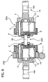
- This steering system is similar to that of the second embodiment shown in FIG. 7, and has a speed change device 20C that is disposed between an upper part and a lower part of an upper steering shaft and has a first variable steering angle ratio mechanism and a second variable steering angle ratio mechanism that are arranged in the same direction as those of the second embodiment.
- the mechanisms have a planetary roller set and a planetary teethed wheel set so that a roller element of the roller set is integrally formed with a teethed wheel element of the teethed wheel set like a construction shown in FIG. 2
- the speed change device 20C is equipped with a hollow electric motor 32 as a steering angle ratio control motor.
- the hollow motor 32 includes a rotor 32a and a stator 32b.
- the rotor 32a is directly connected with a ring roller 8 of a second variable steering angle ratio mechanism, and the stator 32b is fixed on a not-shown case.
- the speed change device 20C has a locking mechanism 34 to lock the hollow motor 32.
- the locking mechanism 34 is equipped with a solenoid 32 and a stopper 34c rotatable around a supporting shaft 34c.
- the solenoid 34a drives the stopper 34c to insert it in one of grooves 33 formed on an outer peripheral surface of the rotor 32a for locking. This locking brings the hollow motor 32 to be held to stop its speed changing function.
- the other parts are similar to the second embodiment.
- This speed change device 20C can be constructed compactly.
- a speed change device 20D for a steering system according to the ninth embodiment of the present invention will be described with reference to the accompanying drawing of FIG. 24.
- This steering system is similar to that of the second embodiment shown in FIG. 7, and has a speed change device 20D that is disposed between an upper part and a lower part of an upper steering shaft and has a first variable steering angle ratio mechanism and a second variable steering angle ratio mechanism that are arranged in the same direction as those of the second embodiment.
- the mechanisms have a planetary roller set and a planetary teethed wheel set so that a roller element of the roller set is integrally formed with a teethed wheel element of the teethed wheel set like a construction shown in FIG. 2.
- the speed change device 20D is provided with spur gears 35 and 27a instead of the worm gears of the first embodiment.
- the spur gear 35 is fixed on the outer peripheral surface of a ring roller 8, and mated with a spur gear 27a provided on an output shaft of an electric motor 27.
- the motor 27 has a locking pin mechanism 36, which includes a solenoid 36a, and locking pin 36b actuated to move forward and backward.
- the solenoid 36a dives the locking pin 36b to be inserted into one of holes 27a formed in a rotatable shaft of the motor 27 to hold the motor 27 for locking to stop its speed changing function.
- the spur gears 27a and 35 may be replaced by helical gears.
- a speed change device for a steering system according to the tenth embodiment of the present invention will be described with reference to the accompanying drawing of FIG. 25.
- This steering system includes a speed change device 201 that is disposed between an upper part 18a and a lower part 18b of an upper steering shaft 18 and has a first variable steering angle ratio mechanism 20A' and a second variable steering angle ratio mechanism 20B.
- the mechanisms 20A' and 20B have a planetary roller set and a planetary teethed wheel set so that a roller element of the roller set is integrally formed with a teethed wheel element of the teethed wheel set like a construction shown in FIG. 2.
- the first variable steering angle ratio mechanism 20A' has a ring roller 37 that is integrally formed with a ring teethed wheel and an outer race and is fixed a not-shown case, while the second variable steering angle ratio mechanism 20B has a ring roller 8 integrally formed with a ring gear supported by an outer race 9 of a needle roller bearing 16 through needle rollers 16a.
- the other parts of the steering system are constructed similarly to those of the second embodiment shown in FIG. 7.
- This steering system of the tenth embodiment can decrease the number of its parts and its cost.
- a speed change device for a steering system according to the eleventh embodiment of the present invention will be described with reference to the accompanying drawing of FIG. 26.
- This steering system includes a speed change device 211 that is disposed between an upper part 18a and a lower part 18b of an upper steering shaft 18 and has a first variable steering angle ratio mechanism 20A' and a second variable steering angle ratio mechanism 20B.
- the mechanisms 20A' and 20B have a planetary roller set and a planetary teethed wheel set so that a roller element of the roller set is integrally formed with a teethed wheel element of the teethed wheel set like a construction shown in FIG. 2.
- the first variable steering angle ratio mechanism 20A' has a ring roller 37 that is integrally formed with a ring teethed wheel and an outer race and is fixed a not-shown case, while the second variable steering angle ratio mechanism 20B has a ring roller 8 integrally formed with a ring gear supported by an outer race 9 of a needle roller bearing 16 through needle rollers 16a.
- the other parts of the steering system are constructed similarly to those of the third embodiment shown in FIG. 9.
- This steering system of the eleventh embodiment can decrease the number of its parts and its cost.
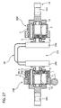
- a speed change device for a steering system according to the twelfth embodiment of the present invention will be described with reference to the accompanying drawing of FIG. 27.
- This steering system includes a speed change device 221 that is disposed between an upper part 18a and a lower part 18b of an upper steering shaft 18 and has a first variable steering angle ratio mechanism 20A' and a second variable steering angle ratio mechanism 20B.
- the mechanisms 20A' and 20B have a planetary roller set and a planetary teethed wheel set so that a roller element of the roller set is integrally formed with a teethed wheel element of the teethed wheel set like a construction shown in FIG. 2.
- the first variable steering angle ratio mechanism 20A' has a ring roller 37 that is integrally formed with a ring teethed wheel and an outer race and is fixed a not-shown case, while the second variable steering angle ratio mechanism 20B has a ring roller 8 integrally formed with a ring gear supported by an outer race 9 of a needle roller bearing 16 through needle rollers 16a.
- the other parts of the steering system are constructed similarly to those of the fourth embodiment shown in FIG. 10.
- This steering system of the twelfth embodiment can decrease the number of its parts and its cost.
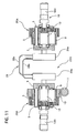
- a speed change device for a steering system according to the thirteenth embodiment of the present invention will be described with reference to the accompanying drawing of FIG. 28.
- This steering system includes a speed change device 231 that is disposed between an upper part 18a and a lower part 18b of an upper steering shaft 18 and has a first variable steering angle ratio mechanism 20A' and a second variable steering angle ratio mechanism 20B.
- the mechanisms 20A' and 20B have a planetary roller set and a planetary teethed wheel set so that a roller element of the roller set is integrally formed with a teethed wheel element of the teethed wheel set like a construction shown in FIG. 2.
- the first variable steering angle ratio mechanism 20A' has a ring roller 37 that is integrally formed with a ring teethed wheel and an outer race and is fixed a not-shown case, while the second variable steering angle ratio mechanism 20B has a ring roller 8 integrally formed with a ring gear supported by an outer race 9 of a needle roller bearing 16 through needle rollers 16a.
- the other parts of the steering system are constructed similarly to those of the fifth embodiment shown in FIG. 11.
- This steering system of the eleventh embodiment can decrease the number of its parts and its cost.
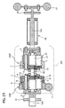
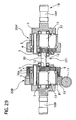
- a speed change device for a steering system according to the fourteenth embodiment of the present invention will be described with reference to the accompanying drawing of FIG. 29.
- This steering system includes a speed change device 251 that is disposed between an upper part 18a and a lower part 18b of an upper steering shaft 18 and has a first variable steering angle ratio mechanism 20A' and a second variable steering angle ratio mechanism 20B.
- the mechanisms 20A' and 20B have a planetary roller set and a planetary teethed wheel set so that a roller element of the roller set is integrally formed with a teethed wheel element of the teethed wheel set like a construction shown in FIG. 2.
- the first variable steering angle ratio mechanism 20A' has a ring roller 37 that is integrally formed with a ring teethed wheel and an outer race and is fixed a not-shown case, while the second variable steering angle ratio mechanism 20B has a ring roller 8 integrally formed with a ring gear supported by an outer race 9 of a needle roller bearing 16 through needle rollers 16a.
- the other parts of the steering system are constructed similarly to those of the seventh embodiment shown in FIG. 21.
- This steering system of the eleventh embodiment can decrease the number of its parts and its cost.
- first and second variable mechanisms 20A and 20B may be connected by a connecting rod instead of the control cable 28 shown in FIGS. 10, 11, 27, and 28.
- a roller and a teethed wheel may be formed independently from each other and connected coaxially with each other.
- a speed change device of this invention can be used in the other fields using the same function thereof, especially for a speed change device having an input member that is rotatable in opposite directions from a normal position within limited rotation angles, the input member transmitting higher torque as a rotation angle thereof from the normal position becomes large.
Landscapes
- Engineering & Computer Science (AREA)
- Mechanical Engineering (AREA)
- Chemical & Material Sciences (AREA)
- Combustion & Propulsion (AREA)
- Transportation (AREA)
- General Engineering & Computer Science (AREA)
- Power Steering Mechanism (AREA)
- Friction Gearing (AREA)
Applications Claiming Priority (6)
| Application Number | Priority Date | Filing Date | Title |
|---|---|---|---|
| JP2004027064 | 2004-02-03 | ||
| JP2004027064 | 2004-02-03 | ||
| JP2004027068 | 2004-02-03 | ||
| JP2004027068 | 2004-02-03 | ||
| JP2004222321 | 2004-07-29 | ||
| JP2004222321 | 2004-07-29 |
Publications (3)
| Publication Number | Publication Date |
|---|---|
| EP1561972A2 true EP1561972A2 (de) | 2005-08-10 |
| EP1561972A3 EP1561972A3 (de) | 2009-10-21 |
| EP1561972B1 EP1561972B1 (de) | 2012-12-26 |
Family
ID=34681982
Family Applications (1)
| Application Number | Title | Priority Date | Filing Date |
|---|---|---|---|
| EP05075280A Expired - Lifetime EP1561972B1 (de) | 2004-02-03 | 2005-02-03 | Getriebe |
Country Status (2)
| Country | Link |
|---|---|
| US (1) | US7244214B2 (de) |
| EP (1) | EP1561972B1 (de) |
Cited By (2)
| Publication number | Priority date | Publication date | Assignee | Title |
|---|---|---|---|---|
| EP1714850A1 (de) * | 2005-04-21 | 2006-10-25 | Mitsubishi Heavy Industries, Ltd. | Planetenreibradantriebsvorrichtung und Lenkeinrichtung mit einer solchen |
| EP1605185A3 (de) * | 2004-06-10 | 2007-04-18 | Mitsubishi Heavy Industries, Ltd. | Planetenrollen-Typ stufenlos regelbares Getriebe |
Families Citing this family (10)
| Publication number | Priority date | Publication date | Assignee | Title |
|---|---|---|---|---|
| JP2007055571A (ja) * | 2005-07-28 | 2007-03-08 | Fuji Kiko Co Ltd | 可変舵角比操舵装置のロック構造 |
| EP1857347B1 (de) * | 2006-05-15 | 2009-08-19 | JTEKT Corporation | Lenkgerät für ein Fahrzeug |
| JP2008024059A (ja) * | 2006-07-18 | 2008-02-07 | Jtekt Corp | 車両用操舵装置 |
| US8518628B2 (en) * | 2006-09-22 | 2013-08-27 | Taiwan Semiconductor Manufacturing Company, Ltd. | Surface switchable photoresist |
| JP2008087672A (ja) * | 2006-10-03 | 2008-04-17 | Jtekt Corp | 車両用操舵装置 |
| US20100258254A1 (en) * | 2009-04-09 | 2010-10-14 | Ben Lumbers | Roller door and a drive assembly for a roller door |
| TWI500907B (zh) * | 2011-01-07 | 2015-09-21 | Oriental Motor Co Ltd | 多圈旋轉絕對旋轉角之檢測裝置及該旋轉角之檢測方法 |
| US11306802B2 (en) * | 2018-04-02 | 2022-04-19 | Dana Limited | Traction device |
| CN108730425B (zh) * | 2018-05-07 | 2021-12-03 | 西安航空制动科技有限公司 | 一种用于机轮速度传感器的行星结构 |
| DE102019212749A1 (de) * | 2018-08-27 | 2020-02-27 | Mando Corporation | Lenksteuervorrichtung |
Family Cites Families (9)
| Publication number | Priority date | Publication date | Assignee | Title |
|---|---|---|---|---|
| JPS5645824B2 (de) * | 1973-10-15 | 1981-10-29 | ||
| SE388468C (sv) * | 1975-06-04 | 1978-10-23 | Skf Nova Ab | Planetvexel med alternerande friktions- och kuggkraftoverforing |
| GB2125927A (en) * | 1982-08-25 | 1984-03-14 | Automotive Products Plc | Vehicle gearboxes |
| JPS6343866A (ja) * | 1986-08-08 | 1988-02-24 | Koyo Seiko Co Ltd | 電動式パワ−ステアリング装置 |
| DE3801461A1 (de) * | 1988-01-20 | 1989-08-03 | Bayerische Motoren Werke Ag | Wechselgetriebe fuer kraftfahrzeuge |
| JPH02190643A (ja) * | 1989-01-13 | 1990-07-26 | Daishowa Seiki Co Ltd | 伝動装置 |
| JPH08291848A (ja) | 1995-04-21 | 1996-11-05 | Nissan Motor Co Ltd | 減速装置 |
| JP4638059B2 (ja) * | 2001-01-15 | 2011-02-23 | 住友重機械工業株式会社 | パラレル駆動の変速機 |
| US6997076B2 (en) * | 2003-02-10 | 2006-02-14 | Delphi Technologies, Inc. | Gear backlash elimination and adjustable gear backlash mechanism |
-
2005
- 2005-02-03 US US11/049,289 patent/US7244214B2/en not_active Expired - Fee Related
- 2005-02-03 EP EP05075280A patent/EP1561972B1/de not_active Expired - Lifetime
Non-Patent Citations (1)
| Title |
|---|
| None |
Cited By (4)
| Publication number | Priority date | Publication date | Assignee | Title |
|---|---|---|---|---|
| EP1605185A3 (de) * | 2004-06-10 | 2007-04-18 | Mitsubishi Heavy Industries, Ltd. | Planetenrollen-Typ stufenlos regelbares Getriebe |
| US7273436B2 (en) | 2004-06-10 | 2007-09-25 | Mitsubishi Heavy Industries Inc. | Planetary-roller-type continuously variable transmission |
| EP1714850A1 (de) * | 2005-04-21 | 2006-10-25 | Mitsubishi Heavy Industries, Ltd. | Planetenreibradantriebsvorrichtung und Lenkeinrichtung mit einer solchen |
| US7604560B2 (en) | 2005-04-21 | 2009-10-20 | Mitsubishi Heavy Industries, Ltd. | Planetary roller driving device and steering apparatus comprising the same |
Also Published As
| Publication number | Publication date |
|---|---|
| US7244214B2 (en) | 2007-07-17 |
| EP1561972A3 (de) | 2009-10-21 |
| EP1561972B1 (de) | 2012-12-26 |
| US20050205340A1 (en) | 2005-09-22 |
Similar Documents
| Publication | Publication Date | Title |
|---|---|---|
| US7736256B2 (en) | Electric power steering device for vehicles applying assist power to rotary member surrounding tie rod connecting bar | |
| US5437583A (en) | Torque distributing mechanism for differential | |
| EP1561972B1 (de) | Getriebe | |
| US7735597B2 (en) | Steering apparatus for vehicle | |
| US7588259B2 (en) | Reduction gear and vehicular active stabilizer system | |
| JP3950456B2 (ja) | 遊星ローラ式無段変速機 | |
| EP2817529B1 (de) | Mechanisch betätigte rollenkupplung mit richtungserkennung | |
| US7604560B2 (en) | Planetary roller driving device and steering apparatus comprising the same | |
| CN112722061A (zh) | 用于车辆转向柱的力矩反馈组件及车辆转向柱 | |
| EP1700772B1 (de) | Kraftfahrzeuglenkung ausgestattet mit einer Einrichtung zur Übertragung einer Drehbewegung | |
| EP0677312A1 (de) | Steuerungsvorrichtung | |
| JP4428100B2 (ja) | ステアリング装置 | |
| US20060191366A1 (en) | Forward-reverse control device | |
| JP2548258B2 (ja) | ベルト式無段変速装置 | |
| JP2006290250A (ja) | 車輌用可変舵角装置 | |
| JP4802504B2 (ja) | 変速装置およびそれを用いた車両用可変舵角装置 | |
| WO2004081412A1 (en) | Forward-reverse control device | |
| JP2006290249A (ja) | 車輌用可変舵角装置 | |
| JP3420330B2 (ja) | 車両の駆動装置 | |
| JP2006290252A (ja) | 車輌用可変舵角装置 | |
| KR101450320B1 (ko) | 볼감속기를 구비한 랙구동형 전동식 조향장치 | |
| JPS6226162A (ja) | 自動車のステアリング装置 | |
| JP2003291825A (ja) | 車両用操舵制御装置 | |
| KR101229236B1 (ko) | 차량 조향 시스템용 감속 장치 | |
| JP2024125072A (ja) | シフト装置 |
Legal Events
| Date | Code | Title | Description |
|---|---|---|---|
| PUAI | Public reference made under article 153(3) epc to a published international application that has entered the european phase |
Free format text: ORIGINAL CODE: 0009012 |
|
| 17P | Request for examination filed |
Effective date: 20050217 |
|
| AK | Designated contracting states |
Kind code of ref document: A2 Designated state(s): AT BE BG CH CY CZ DE DK EE ES FI FR GB GR HU IE IS IT LI LT LU MC NL PL PT RO SE SI SK TR |
|
| AX | Request for extension of the european patent |
Extension state: AL BA HR LV MK YU |
|
| PUAL | Search report despatched |
Free format text: ORIGINAL CODE: 0009013 |
|
| AK | Designated contracting states |
Kind code of ref document: A3 Designated state(s): AT BE BG CH CY CZ DE DK EE ES FI FR GB GR HU IE IS IT LI LT LU MC NL PL PT RO SE SI SK TR |
|
| AX | Request for extension of the european patent |
Extension state: AL BA HR LV MK YU |
|
| AKX | Designation fees paid |
Designated state(s): DE FR GB |
|
| 17Q | First examination report despatched |
Effective date: 20101122 |
|
| GRAP | Despatch of communication of intention to grant a patent |
Free format text: ORIGINAL CODE: EPIDOSNIGR1 |
|
| GRAS | Grant fee paid |
Free format text: ORIGINAL CODE: EPIDOSNIGR3 |
|
| GRAA | (expected) grant |
Free format text: ORIGINAL CODE: 0009210 |
|
| AK | Designated contracting states |
Kind code of ref document: B1 Designated state(s): DE FR GB |
|
| REG | Reference to a national code |
Ref country code: GB Ref legal event code: FG4D |
|
| REG | Reference to a national code |
Ref country code: DE Ref legal event code: R096 Ref document number: 602005037565 Country of ref document: DE Effective date: 20130228 |
|
| PLBE | No opposition filed within time limit |
Free format text: ORIGINAL CODE: 0009261 |
|
| STAA | Information on the status of an ep patent application or granted ep patent |
Free format text: STATUS: NO OPPOSITION FILED WITHIN TIME LIMIT |
|
| REG | Reference to a national code |
Ref country code: DE Ref legal event code: R073 Ref document number: 602005037565 Country of ref document: DE |
|
| REG | Reference to a national code |
Ref country code: FR Ref legal event code: ST Effective date: 20131031 |
|
| REG | Reference to a national code |
Ref country code: DE Ref legal event code: R082 Ref document number: 602005037565 Country of ref document: DE Representative=s name: PATENT- UND RECHTSANWAELTE DIEHL & PARTNER GBR, DE |
|
| 26N | No opposition filed |
Effective date: 20130927 |
|
| REG | Reference to a national code |
Ref country code: DE Ref legal event code: R074 Ref document number: 602005037565 Country of ref document: DE |
|
| REG | Reference to a national code |
Ref country code: DE Ref legal event code: R119 Ref document number: 602005037565 Country of ref document: DE Effective date: 20130903 |
|
| REG | Reference to a national code |
Ref country code: FR Ref legal event code: RN Effective date: 20131126 |
|
| REG | Reference to a national code |
Ref country code: DE Ref legal event code: R074 Ref document number: 602005037565 Country of ref document: DE Effective date: 20131210 Ref country code: DE Ref legal event code: R074 Ref document number: 602005037565 Country of ref document: DE Effective date: 20131213 |
|
| PG25 | Lapsed in a contracting state [announced via postgrant information from national office to epo] |
Ref country code: FR Free format text: LAPSE BECAUSE OF NON-PAYMENT OF DUE FEES Effective date: 20130228 |
|
| REG | Reference to a national code |
Ref country code: FR Ref legal event code: FC Effective date: 20140128 |
|
| PGRI | Patent reinstated in contracting state [announced from national office to epo] |
Ref country code: FR Effective date: 20140317 |
|
| REG | Reference to a national code |
Ref country code: FR Ref legal event code: PLFP Year of fee payment: 12 |
|
| REG | Reference to a national code |
Ref country code: FR Ref legal event code: PLFP Year of fee payment: 13 |
|
| PGFP | Annual fee paid to national office [announced via postgrant information from national office to epo] |
Ref country code: FR Payment date: 20170112 Year of fee payment: 13 |
|
| PGFP | Annual fee paid to national office [announced via postgrant information from national office to epo] |
Ref country code: GB Payment date: 20170201 Year of fee payment: 13 |
|
| PGFP | Annual fee paid to national office [announced via postgrant information from national office to epo] |
Ref country code: DE Payment date: 20180228 Year of fee payment: 14 |
|
| GBPC | Gb: european patent ceased through non-payment of renewal fee |
Effective date: 20180203 |
|
| REG | Reference to a national code |
Ref country code: FR Ref legal event code: ST Effective date: 20181031 |
|
| PG25 | Lapsed in a contracting state [announced via postgrant information from national office to epo] |
Ref country code: GB Free format text: LAPSE BECAUSE OF NON-PAYMENT OF DUE FEES Effective date: 20180203 Ref country code: FR Free format text: LAPSE BECAUSE OF NON-PAYMENT OF DUE FEES Effective date: 20180228 |
|
| REG | Reference to a national code |
Ref country code: DE Ref legal event code: R119 Ref document number: 602005037565 Country of ref document: DE |
|
| PG25 | Lapsed in a contracting state [announced via postgrant information from national office to epo] |
Ref country code: DE Free format text: LAPSE BECAUSE OF NON-PAYMENT OF DUE FEES Effective date: 20190903 |