EP1561963B1 - Method and circuit for controlling the flow rate of the hydraulic oil in the brake cooling system of a vehicle - Google Patents
Method and circuit for controlling the flow rate of the hydraulic oil in the brake cooling system of a vehicle Download PDFInfo
- Publication number
- EP1561963B1 EP1561963B1 EP04106667A EP04106667A EP1561963B1 EP 1561963 B1 EP1561963 B1 EP 1561963B1 EP 04106667 A EP04106667 A EP 04106667A EP 04106667 A EP04106667 A EP 04106667A EP 1561963 B1 EP1561963 B1 EP 1561963B1
- Authority
- EP
- European Patent Office
- Prior art keywords
- oil
- hydraulic
- flow rate
- circuit
- controlling
- Prior art date
- Legal status (The legal status is an assumption and is not a legal conclusion. Google has not performed a legal analysis and makes no representation as to the accuracy of the status listed.)
- Expired - Lifetime
Links
- 239000010720 hydraulic oil Substances 0.000 title claims abstract description 28
- 238000001816 cooling Methods 0.000 title claims abstract description 24
- 238000000034 method Methods 0.000 title claims abstract description 22
- 239000003921 oil Substances 0.000 claims abstract description 51
- 239000002826 coolant Substances 0.000 claims abstract description 11
- XLYOFNOQVPJJNP-UHFFFAOYSA-N water Substances O XLYOFNOQVPJJNP-UHFFFAOYSA-N 0.000 claims description 5
- 238000004590 computer program Methods 0.000 claims 3
- 239000012530 fluid Substances 0.000 description 4
- 230000001965 increasing effect Effects 0.000 description 3
- 230000005540 biological transmission Effects 0.000 description 2
- 230000004913 activation Effects 0.000 description 1
- 238000010276 construction Methods 0.000 description 1
- 239000000498 cooling water Substances 0.000 description 1
- 238000012864 cross contamination Methods 0.000 description 1
- 238000010586 diagram Methods 0.000 description 1
- 230000002708 enhancing effect Effects 0.000 description 1
- 230000007613 environmental effect Effects 0.000 description 1
- 230000002427 irreversible effect Effects 0.000 description 1
- 239000010687 lubricating oil Substances 0.000 description 1
- 238000013021 overheating Methods 0.000 description 1
- 230000011664 signaling Effects 0.000 description 1
Images
Classifications
-
- F—MECHANICAL ENGINEERING; LIGHTING; HEATING; WEAPONS; BLASTING
- F16—ENGINEERING ELEMENTS AND UNITS; GENERAL MEASURES FOR PRODUCING AND MAINTAINING EFFECTIVE FUNCTIONING OF MACHINES OR INSTALLATIONS; THERMAL INSULATION IN GENERAL
- F16D—COUPLINGS FOR TRANSMITTING ROTATION; CLUTCHES; BRAKES
- F16D65/00—Parts or details
- F16D65/78—Features relating to cooling
-
- F—MECHANICAL ENGINEERING; LIGHTING; HEATING; WEAPONS; BLASTING
- F16—ENGINEERING ELEMENTS AND UNITS; GENERAL MEASURES FOR PRODUCING AND MAINTAINING EFFECTIVE FUNCTIONING OF MACHINES OR INSTALLATIONS; THERMAL INSULATION IN GENERAL
- F16D—COUPLINGS FOR TRANSMITTING ROTATION; CLUTCHES; BRAKES
- F16D65/00—Parts or details
- F16D65/78—Features relating to cooling
- F16D2065/783—Features relating to cooling cooling control or adjustment
Definitions
- This invention relates to a method and circuit for controlling the flow rate of the hydraulic oil in the brake cooling system of a vehicle.
- Such a circuit is known from e.g. US 4,440,272 A.
- Some types of vehicles are required to work in extremely low outdoor temperatures, where they may also be parked with the engine off for considerable lengths of time; this may be the case, for example, in arctic environments or wherever the temperature falls well below zero at night. In such conditions, when these vehicles are (re)started it takes them a long time to reach the steady state, especially as regards the temperature of the fluids, such as the engine cooling water, engine lubricating oil, transmission oil and the oil of the brake cooling system, in vehicles equipped with oil-immersed brakes.
- the fluids such as the engine cooling water, engine lubricating oil, transmission oil and the oil of the brake cooling system
- the braking system is housed in a sealed oil bath to guarantee high braking torques while enhancing the vehicle's service life.
- the purpose of this invention is to overcome all the drawbacks described above with a method and circuit for controlling the flow rate of the hydraulic oil in the brake cooling system of a vehicle by appropriately adjusting the flow rate of the hydraulic oil in the brake cooling system, especially in cold start conditions with low outdoor temperatures and cold hydraulic oil.
- This invention relates to a method for controlling the flow rate of the hydraulic oil in the brake cooling system of a vehicle, characterized by the fact that it basically consists of the following steps:
- This invention also relates to a circuit for controlling the flow rate of the hydraulic oil in the brake cooling system of a vehicle, as described more fully in the claims, which are an integral part of this description.
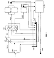
- Figure 1 is a circuit block diagram of a preferred embodiment of the method according to this invention.
- the vehicle is equipped with a hydraulic oil tank of any type that is known, which is illustrated schematically in the drawing and labelled SO.
- a fixed flow-rate pump PM operated by the vehicle's engine, draws up the oil from the tank SO and delivers such oil at a constant flow rate Q COST , regardless of the number of engine revolutions.
- the pump may be of a known type, for example the type used in the power steering circuit. Such pump is flange-mounted on the engine: the number of revolutions varies according to the engine revolutions, but the flow rate remains constant.
- the proportioning valve VP may be of a known type, for example the type used in hydraulic fan drives to control the oil flow according to the fan speed required.
- the proportioning valve VP is controlled by an electronic control unit CNT, for example the so-called body computer that also coordinates the vehicle's engine and transmission functions.
- the control unit operates the valve by means of a valve drive current IP that is proportional to the delivery flow rate Q1.
- the hydraulic oil leaving the proportioning valve VP supplies a hydraulic motor MI, that consists of a motor-driven pump BL that operates a certain number of hydraulic pumps (two in the example, P11, P12).
- the number of revolutions of such motor depends on the input flow rate Q1 controlled by the valve VP. In this way it is possible to control the number of revolutions and the flow rate delivered by the pumps P1, P2 that supply the brake hydraulic oil circuit.
- the brake circuit is divided into sections, there is one pump for each section, for example one section for the front wheels of the vehicle and one section for the rear wheels.
- the number of axles may also vary, for example a vehicle may have one front axle and two rear axles, but of course any number of sections of the hydraulic circuit and axles are possible.
- the pumps of the hydraulic motor PI1 and PI2 draw up oil from the tank SO and deliver such oil to the relative section of the hydraulic circuit.
- the oil thus flows through the respective brake circuits CF1 and CF2 for cooling, and then returns to the tank SO.
- the oil usually flows through an oil/water heat exchanger, not illustrated in the drawing, where the heat is transferred to the engine coolant, thus contributing to the cooling process.
- pressure switches one for each hydraulic circuit, PR1 and PR2 in the example in figure 1, located for example in correspondence with the brakes, that send the relative oil pressure value signals to the control unit CNT. In particular they send an electric signal when a maximum pressure value is exceeded, for example 2.5 bar.
- the DutyVP parameter is defined. This parameter indicates the degree of closure of the proportioning valve VP, which is controlled by means of the current IP, and consequently the flow rate Q1 and thus the flow rate Q olio of the sections of the hydraulic circuit.
- the self-adaptive control of DutyVP in phase 2) consists of gradually ramping down the value of DutyVP (thus increasing the oil pressure) until one of the two pressure switches is activated, and then ramping up again until signalling stops.
- the valve VP is therefore gradually opened and closed and the two pressure switches are used to indicate the maximum and minimum values in the range.
- the control unit opens the valve VP according to a predefined map as a function of the oil temperature.
- a pressure switch incorporated in the circuit sends a signal to the control unit that, on the basis of a self-adaptive algorithm, reduces the flow rate until the alarm signal is switched off.
- control unit CNT processes all the data received from the sensors PR1, PR2, T olio , T H2O , and supplies the drive current IP to the valve VP.
- the procedure of the present invention can be advantageously implemented through a program for computer comprising program coding means for the implementation of one or more steps of the method, when this program is running on a computer. Therefore, it is understood that the scope of protection is extended to such a program for computer and in addition to a computer readable means having a recorded message therein, said computer readable means comprising program coding means for the implementation of one or more steps of the method, when this program is run on a computer.
- the main advantage of a circuit according to this invention is that the flow rate of the hydraulic oil does not depend on the engine speed.
- the maximum flow rate can be achieved even at minimum engine speed, for example when braking to make the vehicle slow down and stop: this is the precise condition in which braking generates the most heat and requires effective cooling, and the availability of maximum pressure in the hydraulic circuit enhances the efficiency of the cooling system. If the oil flow were to be controlled directly by the engine this would result in a reduced flow rate when braking, with the risk of overheating the brake circuit.
Landscapes
- Engineering & Computer Science (AREA)
- General Engineering & Computer Science (AREA)
- Mechanical Engineering (AREA)
- Valves And Accessory Devices For Braking Systems (AREA)
- Braking Arrangements (AREA)
- Regulating Braking Force (AREA)
Applications Claiming Priority (2)
| Application Number | Priority Date | Filing Date | Title |
|---|---|---|---|
| ITMI20040197 | 2004-02-09 | ||
| IT000197A ITMI20040197A1 (it) | 2004-02-09 | 2004-02-09 | Procedimento e circuito per la regolazione della portata di olio idraulico di raffreddamwento freni di un veicolo |
Publications (2)
| Publication Number | Publication Date |
|---|---|
| EP1561963A1 EP1561963A1 (en) | 2005-08-10 |
| EP1561963B1 true EP1561963B1 (en) | 2007-03-07 |
Family
ID=34674569
Family Applications (1)
| Application Number | Title | Priority Date | Filing Date |
|---|---|---|---|
| EP04106667A Expired - Lifetime EP1561963B1 (en) | 2004-02-09 | 2004-12-17 | Method and circuit for controlling the flow rate of the hydraulic oil in the brake cooling system of a vehicle |
Country Status (6)
| Country | Link |
|---|---|
| US (1) | US7513343B2 (it) |
| EP (1) | EP1561963B1 (it) |
| CN (1) | CN1654254A (it) |
| AT (1) | ATE356305T1 (it) |
| DE (1) | DE602004005153T2 (it) |
| IT (1) | ITMI20040197A1 (it) |
Families Citing this family (11)
| Publication number | Priority date | Publication date | Assignee | Title |
|---|---|---|---|---|
| JP4482764B2 (ja) * | 2005-09-30 | 2010-06-16 | Smc株式会社 | 外部配管保護機能をもつ恒温液循環装置 |
| EP1925844A1 (en) * | 2006-11-24 | 2008-05-28 | Caterpillar, Inc. | Method and arrangement for machine cooling |
| JP5180494B2 (ja) * | 2007-03-13 | 2013-04-10 | 日立建機株式会社 | Hstクーリング回路 |
| US7614223B2 (en) * | 2007-03-30 | 2009-11-10 | Clark Equipment Company | Method for operating a multiple speed hydraulic motor |
| US7845471B2 (en) * | 2007-08-22 | 2010-12-07 | Cnh America Llc | External axle cooling system |
| US8281908B2 (en) * | 2008-08-29 | 2012-10-09 | Caterpillar Inc. | Brake cooling fluid diverter for an off-highway machine |
| JP5227772B2 (ja) * | 2008-12-16 | 2013-07-03 | 株式会社小松製作所 | ブレーキ装置の潤滑装置およびその制御方法 |
| DE102010002605B4 (de) * | 2010-03-05 | 2013-12-12 | Ford Global Technologies, Llc | Verfahren zur Verkürzung der Warmlaufphase mittels Wärmerückgewinnung aus rückgeführten Abgasen |
| US8739932B2 (en) | 2011-04-25 | 2014-06-03 | Deere & Company | Axle lubrication and cooling system |
| TWI448401B (zh) * | 2012-02-20 | 2014-08-11 | Univ Nat Formosa | Hydraulic brake device and its control method |
| CN112477835B (zh) * | 2020-11-24 | 2021-09-24 | 湖南工程学院 | 一种电动汽车制动装置的工作方法 |
Family Cites Families (16)
| Publication number | Priority date | Publication date | Assignee | Title |
|---|---|---|---|---|
| DE1907748B1 (de) * | 1969-02-15 | 1972-05-25 | Daimler Benz Ag | Hydrostatische Bremseinrichtung fuer Fahrzeuge,insbesondere fuer Kraftfahrzeuge |
| US3949844A (en) * | 1974-11-15 | 1976-04-13 | Caterpillar Tractor Co. | Brake cooling system with a common fluid mixing chamber |
| US3969897A (en) * | 1975-02-28 | 1976-07-20 | Caterpillar Tractor Co. | Temperature-control arrangement for a pair of hydraulic motors |
| US4083469A (en) * | 1977-03-16 | 1978-04-11 | Caterpillar Tractor Co. | Brake cooling circuit |
| DE3030494C2 (de) * | 1980-08-12 | 1988-07-07 | Zahnradfabrik Friedrichshafen Ag, 7990 Friedrichshafen | Vorrichtung zum Überwachen und Regeln der Bremsleistung eines hydraulischen Retarders |
| DE3539561A1 (de) * | 1985-03-13 | 1986-09-25 | M A N Nutzfahrzeuge GmbH, 8000 München | Hydrostatisches getriebe |
| DE3710028A1 (de) * | 1987-03-27 | 1988-10-06 | Delmag Maschinenfabrik | Druckmittelbetriebene antriebseinrichtung |
| US4845468A (en) * | 1988-01-21 | 1989-07-04 | Dresser Industries, Inc. | Brake condition warning system |
| CA1328896C (en) * | 1988-02-12 | 1994-04-26 | Paul J. Middelhoven | Fail-safe wheel service brake system |
| DE3936735A1 (de) * | 1989-11-04 | 1991-05-08 | Schaeff Karl Gmbh & Co | Hydrostatischer bremsleistungswandler |
| US5507360A (en) * | 1994-10-24 | 1996-04-16 | Caterpillar Inc. | Hydraulic system for dynamic braking and secondary steering system supply |
| US6314729B1 (en) * | 1998-07-23 | 2001-11-13 | Sauer-Danfoss Inc. | Hydraulic fan drive system having a non-dedicated flow source |
| US6030314A (en) * | 1998-09-28 | 2000-02-29 | Caterpillar Inc. | Method and apparatus for retarding a work machine having a fluid-cooled brake system |
| ATE266548T1 (de) * | 2000-09-13 | 2004-05-15 | Fte Automotive Gmbh & Co Kg | Verfahren zur regelung der bremskraft an den rädern eines einspurigen fahrzeugs und bremsanlage zur durchführung des verfahrens |
| JP2002106711A (ja) * | 2000-10-02 | 2002-04-10 | Teijin Seiki Co Ltd | 走行用流体回路 |
| AU2003261558B2 (en) * | 2002-11-15 | 2009-06-11 | Towhaul Corporation | Brake cooling system and method of cooling brakes in an axle |
-
2004
- 2004-02-09 IT IT000197A patent/ITMI20040197A1/it unknown
- 2004-12-17 DE DE602004005153T patent/DE602004005153T2/de not_active Expired - Lifetime
- 2004-12-17 AT AT04106667T patent/ATE356305T1/de not_active IP Right Cessation
- 2004-12-17 EP EP04106667A patent/EP1561963B1/en not_active Expired - Lifetime
- 2004-12-23 CN CN200410102743.6A patent/CN1654254A/zh active Pending
- 2004-12-27 US US11/022,735 patent/US7513343B2/en not_active Expired - Fee Related
Also Published As
| Publication number | Publication date |
|---|---|
| ITMI20040197A1 (it) | 2004-05-09 |
| US7513343B2 (en) | 2009-04-07 |
| DE602004005153T2 (de) | 2007-12-13 |
| DE602004005153D1 (de) | 2007-04-19 |
| EP1561963A1 (en) | 2005-08-10 |
| CN1654254A (zh) | 2005-08-17 |
| US20050173975A1 (en) | 2005-08-11 |
| ATE356305T1 (de) | 2007-03-15 |
Similar Documents
| Publication | Publication Date | Title |
|---|---|---|
| EP1561963B1 (en) | Method and circuit for controlling the flow rate of the hydraulic oil in the brake cooling system of a vehicle | |
| US5941689A (en) | Control system and method to control variable hydraulic pumps with a temperature sensor | |
| EP0812280B1 (en) | Automotive hydraulic system and method | |
| US12228067B2 (en) | Fan speed control system for engine cooling | |
| US6314727B1 (en) | Method and apparatus for controlling an electro-hydraulic fluid system | |
| US11293319B2 (en) | System for regenerating DPF during operation of engine-powered forklift and method therefor | |
| JP2002521602A (ja) | 非専用流体源を有する液圧ファン駆動システム | |
| KR101079796B1 (ko) | 유체의 점도를 제어하기 위한 시스템 및 방법 그리고 이시스템을 포함하는 작업차량 | |
| WO2016104324A1 (ja) | モータ駆動制御装置 | |
| EP1000837A2 (en) | Power steering apparatus | |
| JP6175586B2 (ja) | 駆動力配分装置の油圧制御装置 | |
| JP2013527072A (ja) | 流体式ブレーキのアクセス可能な最大ブレーキ性能を制限するための方法 | |
| CN108397429B (zh) | 用于液压辅助制动及驱动的控制系统及控制方法 | |
| HK1085781A (en) | Method and circuit for controlling the flow rate of the hydraulic oil in the brake cooling system of a vehicle | |
| US20240416992A1 (en) | Hydraulic pump assembly | |
| US8281908B2 (en) | Brake cooling fluid diverter for an off-highway machine | |
| KR101389603B1 (ko) | 건설 기계 조향용 유압 시스템 | |
| EP1763637B1 (en) | Arrangement and method for a compressed air system | |
| US20190170246A1 (en) | Hydrostatic drive having a closed circuit and method for operating the drive | |
| JP2025162783A (ja) | ウォーターポンプ制御装置 | |
| JP2023156911A (ja) | 車両の補助制動装置 | |
| JP6688892B2 (ja) | 車両の制御装置 | |
| DE102022132915A1 (de) | Verfahren zur Steuerung einer nass betriebenen Fahrzeugbremse | |
| KR19990028426U (ko) | 중장비의 유압유 온도제어장치 |
Legal Events
| Date | Code | Title | Description |
|---|---|---|---|
| PUAI | Public reference made under article 153(3) epc to a published international application that has entered the european phase |
Free format text: ORIGINAL CODE: 0009012 |
|
| AK | Designated contracting states |
Kind code of ref document: A1 Designated state(s): AT BE BG CH CY CZ DE DK EE ES FI FR GB GR HU IE IS IT LI LT LU MC NL PL PT RO SE SI SK TR |
|
| AX | Request for extension of the european patent |
Extension state: AL BA HR LV MK YU |
|
| 17P | Request for examination filed |
Effective date: 20060113 |
|
| AKX | Designation fees paid |
Designated state(s): AT BE BG CH CY CZ DE DK EE ES FI FR GB GR HU IE IS IT LI LT LU MC NL PL PT RO SE SI SK TR |
|
| REG | Reference to a national code |
Ref country code: HK Ref legal event code: DE Ref document number: 1085781 Country of ref document: HK |
|
| GRAP | Despatch of communication of intention to grant a patent |
Free format text: ORIGINAL CODE: EPIDOSNIGR1 |
|
| GRAS | Grant fee paid |
Free format text: ORIGINAL CODE: EPIDOSNIGR3 |
|
| GRAA | (expected) grant |
Free format text: ORIGINAL CODE: 0009210 |
|
| AK | Designated contracting states |
Kind code of ref document: B1 Designated state(s): AT BE BG CH CY CZ DE DK EE ES FI FR GB GR HU IE IS IT LI LT LU MC NL PL PT RO SE SI SK TR |
|
| PG25 | Lapsed in a contracting state [announced via postgrant information from national office to epo] |
Ref country code: LI Free format text: LAPSE BECAUSE OF FAILURE TO SUBMIT A TRANSLATION OF THE DESCRIPTION OR TO PAY THE FEE WITHIN THE PRESCRIBED TIME-LIMIT Effective date: 20070307 Ref country code: PL Free format text: LAPSE BECAUSE OF FAILURE TO SUBMIT A TRANSLATION OF THE DESCRIPTION OR TO PAY THE FEE WITHIN THE PRESCRIBED TIME-LIMIT Effective date: 20070307 Ref country code: NL Free format text: LAPSE BECAUSE OF FAILURE TO SUBMIT A TRANSLATION OF THE DESCRIPTION OR TO PAY THE FEE WITHIN THE PRESCRIBED TIME-LIMIT Effective date: 20070307 Ref country code: FI Free format text: LAPSE BECAUSE OF FAILURE TO SUBMIT A TRANSLATION OF THE DESCRIPTION OR TO PAY THE FEE WITHIN THE PRESCRIBED TIME-LIMIT Effective date: 20070307 Ref country code: CH Free format text: LAPSE BECAUSE OF FAILURE TO SUBMIT A TRANSLATION OF THE DESCRIPTION OR TO PAY THE FEE WITHIN THE PRESCRIBED TIME-LIMIT Effective date: 20070307 Ref country code: AT Free format text: LAPSE BECAUSE OF FAILURE TO SUBMIT A TRANSLATION OF THE DESCRIPTION OR TO PAY THE FEE WITHIN THE PRESCRIBED TIME-LIMIT Effective date: 20070307 Ref country code: SI Free format text: LAPSE BECAUSE OF FAILURE TO SUBMIT A TRANSLATION OF THE DESCRIPTION OR TO PAY THE FEE WITHIN THE PRESCRIBED TIME-LIMIT Effective date: 20070307 |
|
| REG | Reference to a national code |
Ref country code: GB Ref legal event code: FG4D |
|
| REG | Reference to a national code |
Ref country code: CH Ref legal event code: EP |
|
| REF | Corresponds to: |
Ref document number: 602004005153 Country of ref document: DE Date of ref document: 20070419 Kind code of ref document: P |
|
| REG | Reference to a national code |
Ref country code: IE Ref legal event code: FG4D |
|
| PG25 | Lapsed in a contracting state [announced via postgrant information from national office to epo] |
Ref country code: ES Free format text: LAPSE BECAUSE OF FAILURE TO SUBMIT A TRANSLATION OF THE DESCRIPTION OR TO PAY THE FEE WITHIN THE PRESCRIBED TIME-LIMIT Effective date: 20070618 |
|
| REG | Reference to a national code |
Ref country code: SE Ref legal event code: TRGR |
|
| PG25 | Lapsed in a contracting state [announced via postgrant information from national office to epo] |
Ref country code: IS Free format text: LAPSE BECAUSE OF FAILURE TO SUBMIT A TRANSLATION OF THE DESCRIPTION OR TO PAY THE FEE WITHIN THE PRESCRIBED TIME-LIMIT Effective date: 20070707 |
|
| PG25 | Lapsed in a contracting state [announced via postgrant information from national office to epo] |
Ref country code: PT Free format text: LAPSE BECAUSE OF FAILURE TO SUBMIT A TRANSLATION OF THE DESCRIPTION OR TO PAY THE FEE WITHIN THE PRESCRIBED TIME-LIMIT Effective date: 20070807 |
|
| NLV1 | Nl: lapsed or annulled due to failure to fulfill the requirements of art. 29p and 29m of the patents act | ||
| ET | Fr: translation filed | ||
| REG | Reference to a national code |
Ref country code: CH Ref legal event code: PL |
|
| PG25 | Lapsed in a contracting state [announced via postgrant information from national office to epo] |
Ref country code: SK Free format text: LAPSE BECAUSE OF FAILURE TO SUBMIT A TRANSLATION OF THE DESCRIPTION OR TO PAY THE FEE WITHIN THE PRESCRIBED TIME-LIMIT Effective date: 20070307 |
|
| PG25 | Lapsed in a contracting state [announced via postgrant information from national office to epo] |
Ref country code: CZ Free format text: LAPSE BECAUSE OF FAILURE TO SUBMIT A TRANSLATION OF THE DESCRIPTION OR TO PAY THE FEE WITHIN THE PRESCRIBED TIME-LIMIT Effective date: 20070307 Ref country code: RO Free format text: LAPSE BECAUSE OF FAILURE TO SUBMIT A TRANSLATION OF THE DESCRIPTION OR TO PAY THE FEE WITHIN THE PRESCRIBED TIME-LIMIT Effective date: 20070307 |
|
| PLBE | No opposition filed within time limit |
Free format text: ORIGINAL CODE: 0009261 |
|
| STAA | Information on the status of an ep patent application or granted ep patent |
Free format text: STATUS: NO OPPOSITION FILED WITHIN TIME LIMIT |
|
| PG25 | Lapsed in a contracting state [announced via postgrant information from national office to epo] |
Ref country code: DK Free format text: LAPSE BECAUSE OF FAILURE TO SUBMIT A TRANSLATION OF THE DESCRIPTION OR TO PAY THE FEE WITHIN THE PRESCRIBED TIME-LIMIT Effective date: 20070307 |
|
| 26N | No opposition filed |
Effective date: 20071210 |
|
| PG25 | Lapsed in a contracting state [announced via postgrant information from national office to epo] |
Ref country code: LT Free format text: LAPSE BECAUSE OF FAILURE TO SUBMIT A TRANSLATION OF THE DESCRIPTION OR TO PAY THE FEE WITHIN THE PRESCRIBED TIME-LIMIT Effective date: 20070307 |
|
| PG25 | Lapsed in a contracting state [announced via postgrant information from national office to epo] |
Ref country code: GR Free format text: LAPSE BECAUSE OF FAILURE TO SUBMIT A TRANSLATION OF THE DESCRIPTION OR TO PAY THE FEE WITHIN THE PRESCRIBED TIME-LIMIT Effective date: 20070608 |
|
| PG25 | Lapsed in a contracting state [announced via postgrant information from national office to epo] |
Ref country code: MC Free format text: LAPSE BECAUSE OF NON-PAYMENT OF DUE FEES Effective date: 20071231 |
|
| PG25 | Lapsed in a contracting state [announced via postgrant information from national office to epo] |
Ref country code: IE Free format text: LAPSE BECAUSE OF NON-PAYMENT OF DUE FEES Effective date: 20071217 |
|
| REG | Reference to a national code |
Ref country code: HK Ref legal event code: WD Ref document number: 1085781 Country of ref document: HK |
|
| PG25 | Lapsed in a contracting state [announced via postgrant information from national office to epo] |
Ref country code: EE Free format text: LAPSE BECAUSE OF FAILURE TO SUBMIT A TRANSLATION OF THE DESCRIPTION OR TO PAY THE FEE WITHIN THE PRESCRIBED TIME-LIMIT Effective date: 20070307 |
|
| PG25 | Lapsed in a contracting state [announced via postgrant information from national office to epo] |
Ref country code: CY Free format text: LAPSE BECAUSE OF FAILURE TO SUBMIT A TRANSLATION OF THE DESCRIPTION OR TO PAY THE FEE WITHIN THE PRESCRIBED TIME-LIMIT Effective date: 20070307 |
|
| PG25 | Lapsed in a contracting state [announced via postgrant information from national office to epo] |
Ref country code: LU Free format text: LAPSE BECAUSE OF NON-PAYMENT OF DUE FEES Effective date: 20071217 Ref country code: BG Free format text: LAPSE BECAUSE OF FAILURE TO SUBMIT A TRANSLATION OF THE DESCRIPTION OR TO PAY THE FEE WITHIN THE PRESCRIBED TIME-LIMIT Effective date: 20070607 |
|
| PG25 | Lapsed in a contracting state [announced via postgrant information from national office to epo] |
Ref country code: TR Free format text: LAPSE BECAUSE OF FAILURE TO SUBMIT A TRANSLATION OF THE DESCRIPTION OR TO PAY THE FEE WITHIN THE PRESCRIBED TIME-LIMIT Effective date: 20070307 Ref country code: HU Free format text: LAPSE BECAUSE OF FAILURE TO SUBMIT A TRANSLATION OF THE DESCRIPTION OR TO PAY THE FEE WITHIN THE PRESCRIBED TIME-LIMIT Effective date: 20070908 |
|
| PG25 | Lapsed in a contracting state [announced via postgrant information from national office to epo] |
Ref country code: IT Free format text: LAPSE BECAUSE OF NON-PAYMENT OF DUE FEES Effective date: 20071217 |
|
| PGRI | Patent reinstated in contracting state [announced from national office to epo] |
Ref country code: IT Effective date: 20110616 |
|
| REG | Reference to a national code |
Ref country code: FR Ref legal event code: PLFP Year of fee payment: 12 |
|
| PGFP | Annual fee paid to national office [announced via postgrant information from national office to epo] |
Ref country code: GB Payment date: 20151216 Year of fee payment: 12 Ref country code: DE Payment date: 20151208 Year of fee payment: 12 |
|
| PGFP | Annual fee paid to national office [announced via postgrant information from national office to epo] |
Ref country code: FR Payment date: 20151110 Year of fee payment: 12 Ref country code: SE Payment date: 20151211 Year of fee payment: 12 Ref country code: BE Payment date: 20151207 Year of fee payment: 12 |
|
| PG25 | Lapsed in a contracting state [announced via postgrant information from national office to epo] |
Ref country code: BE Free format text: LAPSE BECAUSE OF NON-PAYMENT OF DUE FEES Effective date: 20161231 |
|
| REG | Reference to a national code |
Ref country code: DE Ref legal event code: R119 Ref document number: 602004005153 Country of ref document: DE |
|
| REG | Reference to a national code |
Ref country code: SE Ref legal event code: EUG |
|
| GBPC | Gb: european patent ceased through non-payment of renewal fee |
Effective date: 20161217 |
|
| PG25 | Lapsed in a contracting state [announced via postgrant information from national office to epo] |
Ref country code: SE Free format text: LAPSE BECAUSE OF NON-PAYMENT OF DUE FEES Effective date: 20161218 |
|
| REG | Reference to a national code |
Ref country code: FR Ref legal event code: ST Effective date: 20170831 |
|
| PG25 | Lapsed in a contracting state [announced via postgrant information from national office to epo] |
Ref country code: FR Free format text: LAPSE BECAUSE OF NON-PAYMENT OF DUE FEES Effective date: 20170102 |
|
| PG25 | Lapsed in a contracting state [announced via postgrant information from national office to epo] |
Ref country code: DE Free format text: LAPSE BECAUSE OF NON-PAYMENT OF DUE FEES Effective date: 20170701 Ref country code: GB Free format text: LAPSE BECAUSE OF NON-PAYMENT OF DUE FEES Effective date: 20161217 |
|
| REG | Reference to a national code |
Ref country code: BE Ref legal event code: MM Effective date: 20161231 |
|
| PGFP | Annual fee paid to national office [announced via postgrant information from national office to epo] |
Ref country code: IT Payment date: 20171211 Year of fee payment: 14 |
|
| PG25 | Lapsed in a contracting state [announced via postgrant information from national office to epo] |
Ref country code: IT Free format text: LAPSE BECAUSE OF NON-PAYMENT OF DUE FEES Effective date: 20181217 |