US7845471B2 - External axle cooling system - Google Patents
External axle cooling system Download PDFInfo
- Publication number
- US7845471B2 US7845471B2 US11/843,232 US84323207A US7845471B2 US 7845471 B2 US7845471 B2 US 7845471B2 US 84323207 A US84323207 A US 84323207A US 7845471 B2 US7845471 B2 US 7845471B2
- Authority
- US
- United States
- Prior art keywords
- axle
- fluid
- cooling
- axle shaft
- circuit
- Prior art date
- Legal status (The legal status is an assumption and is not a legal conclusion. Google has not performed a legal analysis and makes no representation as to the accuracy of the status listed.)
- Active, expires
Links
Images


Classifications
-
- F—MECHANICAL ENGINEERING; LIGHTING; HEATING; WEAPONS; BLASTING
- F16—ENGINEERING ELEMENTS AND UNITS; GENERAL MEASURES FOR PRODUCING AND MAINTAINING EFFECTIVE FUNCTIONING OF MACHINES OR INSTALLATIONS; THERMAL INSULATION IN GENERAL
- F16H—GEARING
- F16H57/00—General details of gearing
- F16H57/04—Features relating to lubrication or cooling or heating
- F16H57/048—Type of gearings to be lubricated, cooled or heated
- F16H57/0482—Gearings with gears having orbital motion
- F16H57/0483—Axle or inter-axle differentials
-
- B—PERFORMING OPERATIONS; TRANSPORTING
- B60—VEHICLES IN GENERAL
- B60B—VEHICLE WHEELS; CASTORS; AXLES FOR WHEELS OR CASTORS; INCREASING WHEEL ADHESION
- B60B35/00—Axle units; Parts thereof ; Arrangements for lubrication of axles
- B60B35/12—Torque-transmitting axles
-
- B—PERFORMING OPERATIONS; TRANSPORTING
- B60—VEHICLES IN GENERAL
- B60B—VEHICLE WHEELS; CASTORS; AXLES FOR WHEELS OR CASTORS; INCREASING WHEEL ADHESION
- B60B35/00—Axle units; Parts thereof ; Arrangements for lubrication of axles
- B60B35/12—Torque-transmitting axles
- B60B35/16—Axle housings
-
- F—MECHANICAL ENGINEERING; LIGHTING; HEATING; WEAPONS; BLASTING
- F16—ENGINEERING ELEMENTS AND UNITS; GENERAL MEASURES FOR PRODUCING AND MAINTAINING EFFECTIVE FUNCTIONING OF MACHINES OR INSTALLATIONS; THERMAL INSULATION IN GENERAL
- F16D—COUPLINGS FOR TRANSMITTING ROTATION; CLUTCHES; BRAKES
- F16D65/00—Parts or details
- F16D65/78—Features relating to cooling
- F16D65/84—Features relating to cooling for disc brakes
- F16D65/853—Features relating to cooling for disc brakes with closed cooling system
-
- F—MECHANICAL ENGINEERING; LIGHTING; HEATING; WEAPONS; BLASTING
- F16—ENGINEERING ELEMENTS AND UNITS; GENERAL MEASURES FOR PRODUCING AND MAINTAINING EFFECTIVE FUNCTIONING OF MACHINES OR INSTALLATIONS; THERMAL INSULATION IN GENERAL
- F16N—LUBRICATING
- F16N7/00—Arrangements for supplying oil or unspecified lubricant from a stationary reservoir or the equivalent in or on the machine or member to be lubricated
- F16N7/38—Arrangements for supplying oil or unspecified lubricant from a stationary reservoir or the equivalent in or on the machine or member to be lubricated with a separate pump; Central lubrication systems
- F16N7/40—Arrangements for supplying oil or unspecified lubricant from a stationary reservoir or the equivalent in or on the machine or member to be lubricated with a separate pump; Central lubrication systems in a closed circulation system
-
- B—PERFORMING OPERATIONS; TRANSPORTING
- B60—VEHICLES IN GENERAL
- B60B—VEHICLE WHEELS; CASTORS; AXLES FOR WHEELS OR CASTORS; INCREASING WHEEL ADHESION
- B60B2310/00—Manufacturing methods
- B60B2310/30—Manufacturing methods joining
- B60B2310/302—Manufacturing methods joining by welding
-
- B—PERFORMING OPERATIONS; TRANSPORTING
- B60—VEHICLES IN GENERAL
- B60B—VEHICLE WHEELS; CASTORS; AXLES FOR WHEELS OR CASTORS; INCREASING WHEEL ADHESION
- B60B2310/00—Manufacturing methods
- B60B2310/30—Manufacturing methods joining
- B60B2310/303—Manufacturing methods joining by soldering
-
- B—PERFORMING OPERATIONS; TRANSPORTING
- B60—VEHICLES IN GENERAL
- B60B—VEHICLE WHEELS; CASTORS; AXLES FOR WHEELS OR CASTORS; INCREASING WHEEL ADHESION
- B60B2360/00—Materials; Physical forms thereof
- B60B2360/10—Metallic materials
-
- B—PERFORMING OPERATIONS; TRANSPORTING
- B60—VEHICLES IN GENERAL
- B60B—VEHICLE WHEELS; CASTORS; AXLES FOR WHEELS OR CASTORS; INCREASING WHEEL ADHESION
- B60B2360/00—Materials; Physical forms thereof
- B60B2360/10—Metallic materials
- B60B2360/102—Steel
-
- B—PERFORMING OPERATIONS; TRANSPORTING
- B60—VEHICLES IN GENERAL
- B60B—VEHICLE WHEELS; CASTORS; AXLES FOR WHEELS OR CASTORS; INCREASING WHEEL ADHESION
- B60B2360/00—Materials; Physical forms thereof
- B60B2360/10—Metallic materials
- B60B2360/104—Aluminum
-
- B—PERFORMING OPERATIONS; TRANSPORTING
- B60—VEHICLES IN GENERAL
- B60B—VEHICLE WHEELS; CASTORS; AXLES FOR WHEELS OR CASTORS; INCREASING WHEEL ADHESION
- B60B2360/00—Materials; Physical forms thereof
- B60B2360/14—Physical forms of metallic parts
- B60B2360/147—Castings
-
- B—PERFORMING OPERATIONS; TRANSPORTING
- B60—VEHICLES IN GENERAL
- B60B—VEHICLE WHEELS; CASTORS; AXLES FOR WHEELS OR CASTORS; INCREASING WHEEL ADHESION
- B60B2900/00—Purpose of invention
- B60B2900/50—Improvement of
- B60B2900/513—Cooling, e.g. of brakes
-
- Y—GENERAL TAGGING OF NEW TECHNOLOGICAL DEVELOPMENTS; GENERAL TAGGING OF CROSS-SECTIONAL TECHNOLOGIES SPANNING OVER SEVERAL SECTIONS OF THE IPC; TECHNICAL SUBJECTS COVERED BY FORMER USPC CROSS-REFERENCE ART COLLECTIONS [XRACs] AND DIGESTS
- Y10—TECHNICAL SUBJECTS COVERED BY FORMER USPC
- Y10T—TECHNICAL SUBJECTS COVERED BY FORMER US CLASSIFICATION
- Y10T74/00—Machine element or mechanism
- Y10T74/21—Elements
- Y10T74/2186—Gear casings
- Y10T74/2189—Cooling
Definitions
- the present invention relates generally to the field of work vehicles. It relates more particularly to removal of braking heat from an axle of a wheeled loader.
- wheel or live axle brakes are generally used to first bring the vehicle to a stop. When this is done frequently, the brakes become overheated.
- axle lubricant consequently becomes excessively hot (e.g., above 300 degrees Fahrenheit). This is injurious not only to the lubricant itself (accelerating oxidation and breakdown), but also to the bearings and seals associated with the axle shaft.
- the brake is a wet multiple disk brake; “wet”, because the disks rotate through a bath of lubricating oil. As the multiple brake disks rotate through the lubricating oil, braking heat is transferred from the disks to the lubricating oil.
- the temperature of the lubricating oil consequently increases, and some of the heat within the lubricating oil is transferred to the axle shaft and to the axle housing.
- the axle shaft and axle housing are of limited size and mass and, hence, of limited heat capacity. Therefore, their temperatures begin to approach (under the duty cycle of frequent stops characteristic of a loader) the temperature of the lubricating oil because ambient air typically does not convect heat from the axle housing as rapidly as the brake convects heat into the lubricating oil. It is therefore necessary to actively cool the lubricating oil.
- the present invention relates to a work vehicle including a frame and a first axle assembly coupled to the frame and including a first axle shaft, a second axle shaft and a first axle housing.
- the first and second axle shaft are disposed substantially within the first axle housing.
- a first wheel is coupled to the first axle shaft and a second wheel coupled to the second axle shaft of the first axle assembly.
- a second axle assembly is coupled to the frame and includes a third axle shaft, a fourth axle shaft and a second axle housing.
- the third and fourth axle shaft are disposed substantially within the second axle housing.
- a third wheel is coupled to the third axle shaft and a fourth wheel coupled to the fourth axle shaft of the second axle assembly.
- An axle lubricating fluid is disposed within the first and second axle housing.
- a first cooling fluid circuit is fluidly coupled to the first axle to circulate axle lubricating fluid therethrough, the first cooling circuit including a first fluid pump.
- a second cooling fluid circuit is fluidly coupled to the second axle to circulate axle lubricating fluid therethrough, the second cooling circuit including a second fluid pump.
- a hydraulic motor is fluidly coupled to a third fluid circuit. The motor simultaneously controls both the first and the second fluid pumps, wherein the motor discontinues operation in response to fluid pressure of at least one of the first and second circuit exceeding a predetermined value.
- the present invention further relates to a work vehicle including a frame and a first axle assembly coupled to the frame and including a first axle shaft, a second axle shaft and a first axle housing.
- the first and second axle shaft are disposed substantially within the first axle housing.
- a first wheel is coupled to the first axle shaft and a second wheel is coupled to the second axle shaft of the first axle assembly.
- a second axle assembly is coupled to the frame and includes a third axle shaft, a fourth axle shaft and a second axle housing.
- the third and fourth axle shaft are disposed substantially within the second axle housing.
- a third wheel is coupled to the third axle shaft and a fourth wheel is coupled to the fourth axle shaft of the second axle assembly.
- An axle lubricating fluid is disposed within the first and second axle housing.
- An advantage of the present invention is the apparatus reduces excessive heat from the axle lubricant associated with operation of a work machine.
- FIG. 1 is a rear sectional elevation view of an axle assembly of a work vehicle.
- FIG. 2 is a schematic diagram of an embodiment of an axle cooling apparatus for cooling two axle assemblies.
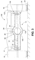
- FIG. 3 is a rear sectional elevation view of an axle assembly of a work vehicle according to another embodiment.
- FIG. 1 shows a work vehicle 10 provided with a frame 12 , an axle assembly 14 , wheels 16 , and an axle cooling apparatus 18 .
- Frame 12 may be of any of the conventional types including fabricated steel or cast iron.
- Axle assembly 14 and axle cooling apparatus 18 are described below, and wheel 16 may be of any of the conventional types; e.g., rubber-tired, cleated, or tracked.
- Wheels 16 support axle assembly 14 with respect to a pavement or ground surface 20 , and axle assembly 14 supports frame 12 . Only one axle assembly 14 is shown, but work vehicle 10 may include any number of axle assemblies 14 .
- Axle assembly 14 includes at least one axle shaft 22 generally contained within an axle housing 24 and supported by axle housing 24 for rotative movement relative to axle housing 24 .
- Axle shaft 22 is of conventional construction, typically machined of a medium-carbon steel and hardened at least in the regions of splines (not shown).
- Axle housing 24 is also generally of conventional construction (e.g., cast gray or ductile iron or fabricated of steel), but is of generally large transverse sectional size to accommodate a brake 26 and a cooling device, or coil 28 (both described below), as well as a planetary gearset (not shown).
- Axle housing 24 may be of any transverse sectional shape; e.g., round, square, etc.
- Brake 26 shown schematically in FIG. 1 , is, in an exemplary embodiment, a wet multidisk brake of well-known and conventional design.
- the term “wet” refers to a bath of lubricating fluid 30 that at least partially immerses brake 26 , lubricating fluid 30 thereby providing both lubrication and cooling of brake 26 .
- a cooling device shown as a coil 28 and a portion of axle cooling apparatus 18 (described below), is also housed within axle housing 24 .
- Coil 28 is a tubular device having a passage 32 provided internally therethrough, is of generally conventional construction and is fabricated of a plurality of metal tubes 34 , generally similar to a tube bundle of a shell-and-tube heat exchanger.
- coil 28 is formed of a single length of tubing in one or more parallel “passes” by a series of 180 degree bends, providing a plurality of parallel tube lengths, each length connected to an adjacent length at one end so that the passes are disposed in serial flow arrangement and coil 28 has one inlet port 36 and one outlet port 38 .
- a coil is fabricated of a plurality of cut tube lengths joined to each other by “U”-shaped return bend fittings, themselves fabricated, if necessary, of a street elbow secured and sealed to a conventional elbow.
- coil 28 includes fins, dimples, or is flattened to increase the surface area thereof in contact with lubricating fluid 30 , and thereby to increase the heat transfer from lubricating fluid 30 to coil 28 .
- axle assembly 14 includes a second coil 28 a , generally similar to first coil 28 described above.
- Second coil 28 a is fluidly disposed in parallel flow relationship to first coil 28 .
- Inlet port 36 of first coil 28 is in fluid communication with inlet port 36 a of second coil 28 a
- outlet port 38 of first coil 28 is in fluid communication with outlet port 38 a of second coil 28 a .
- second coil 28 a is fluidly disposed in series flow relationship to first coil 28 by use of a connector, shown as a crossover conduit 56 .
- Outlet port 38 of first coil 28 delivers cooling fluid to inlet port 36 a of second coil 28 .
- This configuration provides a greater length of time for any given particle of cooling fluid to absorb heat from coils 28 and 28 a at a relatively low flow rate, providing a relatively large efficiency of cooling in terms of the quantity of thermal units transferred per unit of cooling fluid volume.
- Coils 28 , 28 a are disposed near an inner bottom surface of axle housing 24 to ensure its immersion in lubricating oil in various pitch and roll angles of work vehicle 10 .
- at least the lower portion of axle housing 24 is of a square transverse sectional shape so that coils 28 , 28 a may be formed of a flat sectional shape.
- the transverse sectional shape of an axle housing is generally circular and the sectional shape of a coil is that of a segment of a circle having a slightly smaller radius than that of an inner surface of the axle housing.
- Passage 32 within coils 28 , 28 a is filled with a cooling fluid 41 (circulating in cooling circuits 42 , 44 in FIG. 2 ).
- cooling fluid 41 is of a high pressure (e.g., greater than 80 pounds per square inch)
- coils 28 , 28 a are preferably fashioned of a formable steel tube material and secured to fittings by welding or brazing.
- cooling fluid 41 is of a lower pressure
- coils 28 , 28 a may advantageously be fashioned of a copper alloy (e.g., a soft brass) or an aluminum alloy for higher thermal conductivity and therefore a higher rate of heat transfer.
- Cooling fluid 41 may be any of fluid, liquid or gaseous, with sufficient heat capacity and flow rate to remove braking heat from coils 28 , 28 a . Since, however, most examples of work vehicle 10 , such as a loader, are provided with hydraulic systems which include a hydraulic fluid generally maintained much lower than 300 degrees in temperature and otherwise suitable for removing heat from coils 28 , 28 a , in an exemplary embodiment work vehicle 10 uses hydraulic fluid obtained from an existing work vehicle hydraulic system as cooling fluid 41 .
- FIG. 2 is a schematic diagram of axle cooling circuit 42 for an axle cooling apparatus 18 having one coil 28 or coils 28 , 28 a for cooling of an axle assembly 14 .
- FIG. 2 further shows an axle cooling circuit 44 for a second axle assembly 14 .
- Cooling apparatus 18 is a portion of a much larger and more complex hydraulic power circuit.
- cooling circuits 42 , 44 receive cooling from a fluid circuit associated with driving a fan valve 52 , as will be discussed in additional detail below.
- fluid circuits for other systems or subsystems may also be used.
- components, such as filters 68 are shown at optional locations in FIG. 2 , but not further discussed.
- lubricating fluid 30 may be maintained separately from cooling fluid 41 , in one embodiment, lubricating fluid 30 and cooling fluid 41 may be the same fluid.
- the fluid circuit associated with driving fan valve 52 includes a reservoir 46 for circulating cooling fluid 40 that is drawn therefrom by a pump 48 .
- Pump 48 may include one or more pumps disposed in a desirable arrangement. Pump 48 delivers a cooling fluid 40 through line 50 to fan valve 52 .
- An optional thermal bypass valve 54 downstream of fan valve 52 when actuated, directs cooling fluid 40 through lines 57 and 60 , thereby bypassing line 55 and heat exchanger 58 . Bypassing heat exchanger 58 prevents undesired cooling of cooling fluid 40 , such as during operation in extremely cold conditions.
- flow of cooling fluid 40 may be bifurcated through heat exchangers 62 and 64 .
- cooling fluid 40 is placed in thermal communication with cooling fluid 41 of cooling circuit 44 to cool lubricating fluid 30 ( FIG. 1 ) in axle assembly 14 .
- Cooling fluid 41 of cooling circuit 44 is circulated by a pump 80 .
- cooling fluid 40 is placed in thermal communication with cooling fluid 41 of cooling circuit 42 to cool lubricating fluid 30 ( FIG. 1 ) in axle assembly 14 .
- Cooling fluid 41 of cooling circuit 42 is circulated by a pump 82 .
- Pumps 80 , 82 are driven by a motor 78 that is associated with a separate fluid circuit, which is further discussed below. After flowing though heat exchangers 62 , 64 , cooling fluid 40 is returned through return line 66 to reservoir 46 .
- FIG. 2 further shows the separate fluid circuit associated with motor 78 .
- a line 70 delivers cooling fluid 40 from pump 48 to brake valve 72 which operates brake 26 ( FIG. 1 ). After flowing through brake valve 72 , cooling fluid 40 is directed to flow through line 74 to operate motor 78 , which in turn operates pumps 80 , 82 to circulate cooling liquid 41 through respective cooling circuits 42 , 44 .
- motor 78 includes a shaft (not shown) that is connected to each of pumps 80 , 82 .
- motor 78 may be connected to pumps 80 , 82 by a belt or chain drive, or other arrangement permitting the motor to operate the pumps. In operation, motor 78 rotates the shaft, which rotational shaft movement likewise operates pumps 80 , 82 .
- motor 78 may operate more than two pumps, if desired, and that the pumps may have different operational capacities with respect to each other.
- a pressure relief valve 76 is arranged in parallel with motor 78 . This parallel arrangement limits the power of motor 78 , and likewise limits the power available at pumps 80 , 82 , thereby reducing negative effects of cavitation that may occur when the work vehicle operates in extremely cold conditions.
- motor 78 in response to increased fluid pressure values, such as brought about by extremely cold conditions sufficiently increasing the fluid viscosity of fluid flowing through at least one, or both of cooling circuits 42 , 44 , as sensed by pressure relief valve 76 , motor 78 discontinues operation.
- a motor resistance and hydraulic pressure relief discussed above may be used to eliminate the need for an electrical control system requiring sensors, such as temperature sensors, and a controller to electrically operate a motor, further requiring an electronic clutch, thereby avoiding such expenses.
- first axle shaft 22 and a second axle shaft may be connected to opposite sides of a differential gearset 84 (shown in FIG. 1 ).
- a differential housing 86 configured to include a chamber 88 to accommodate differential gearset 84 , is then provided to support and shield differential gearset 84 and to contain a lubricant for differential gearset 84 .
- this lubricant will be similar to lubricating fluid 30 , and one common bath of lubricating fluid 30 may be used for lubrication of differential gearset 84 as well as for lubrication and cooling of other parts of axle assembly 14 .
- Crossover conduit 56 may then be given the bowed shape shown in FIG. 1 in order to not interfere with differential gearset 84 .
- heat exchanger 58 is shown as an air-to-oil type heat exchanger and that heat exchangers 62 , 64 are oil-to-oil type heat exchangers, other heat exchanger types may be used, including but not limited to water-to-oil.
- FIG. 3 In another embodiment of work vehicle 100 shown in FIG. 3 , which is otherwise similar to work vehicle 10 , there is no coil 28 , 28 a disposed in axle housing 24 to circulate lubricating fluid 30 for purposes of heat transfer from brake 26 .
- an inlet port 136 is disposed adjacent to brake 26 , and in one embodiment, to both brakes 26 .
- a discharge port 138 of a discharge line 140 is disposed adjacent to differential gearset 84 .
- the axle cooling fluid 41 and lubricating fluid 30 are the same fluid in axle assembly 14 .
- cooling fluid 41 enters inlet port 136 and is sprayed onto brake 26 . Simultaneously, lubricating fluid 30 exits axle assembly 14 via discharge port 138 of discharge line 140 , and upon exiting axle assembly 14 becomes cooling fluid 41 .
Landscapes
- Engineering & Computer Science (AREA)
- General Engineering & Computer Science (AREA)
- Mechanical Engineering (AREA)
- General Details Of Gearings (AREA)
Abstract
Description
Claims (17)
Priority Applications (1)
| Application Number | Priority Date | Filing Date | Title |
|---|---|---|---|
| US11/843,232 US7845471B2 (en) | 2007-08-22 | 2007-08-22 | External axle cooling system |
Applications Claiming Priority (1)
| Application Number | Priority Date | Filing Date | Title |
|---|---|---|---|
| US11/843,232 US7845471B2 (en) | 2007-08-22 | 2007-08-22 | External axle cooling system |
Publications (2)
| Publication Number | Publication Date |
|---|---|
| US20090050412A1 US20090050412A1 (en) | 2009-02-26 |
| US7845471B2 true US7845471B2 (en) | 2010-12-07 |
Family
ID=40381113
Family Applications (1)
| Application Number | Title | Priority Date | Filing Date |
|---|---|---|---|
| US11/843,232 Active 2028-07-02 US7845471B2 (en) | 2007-08-22 | 2007-08-22 | External axle cooling system |
Country Status (1)
| Country | Link |
|---|---|
| US (1) | US7845471B2 (en) |
Cited By (6)
| Publication number | Priority date | Publication date | Assignee | Title |
|---|---|---|---|---|
| US20090050424A1 (en) * | 2007-08-22 | 2009-02-26 | Michael Sylvester Bares | Axle Cooling Using Hydraulic Return Oil |
| US8739932B2 (en) | 2011-04-25 | 2014-06-03 | Deere & Company | Axle lubrication and cooling system |
| US9764671B2 (en) | 2015-05-07 | 2017-09-19 | Caterpillar Inc. | Unloading relief valve |
| US11320013B1 (en) * | 2020-10-15 | 2022-05-03 | Towhaul Corporation | Brake cooling system and method of cooling brakes in an axle assembly |
| DE102021213838A1 (en) | 2021-02-02 | 2022-08-04 | Deere & Company | AXLE OIL TEMPERATURE CONTROL SYSTEMS AND METHODS |
| US11448362B2 (en) * | 2019-07-01 | 2022-09-20 | Deere & Company | Axle cooling system and method |
Families Citing this family (5)
| Publication number | Priority date | Publication date | Assignee | Title |
|---|---|---|---|---|
| CN102152714B (en) * | 2011-03-14 | 2012-10-10 | 广东富华重工制造有限公司 | Improving structure of drive axle shell |
| US10100977B2 (en) * | 2013-07-05 | 2018-10-16 | Volvo Construction Equipment Ab | Liquid distribution system |
| CN107763122A (en) * | 2017-12-19 | 2018-03-06 | 合肥长安汽车有限公司 | A kind of new automobile brakes heat abstractor |
| CN108674092B (en) * | 2018-04-28 | 2023-11-10 | 徐州美驰车桥有限公司 | Axle capable of controlling temperature of lubricating oil and monitoring quality of lubricating oil and control method |
| DE102021209648A1 (en) | 2021-09-02 | 2023-03-02 | Volkswagen Aktiengesellschaft | Drive train for a motor vehicle |
Citations (23)
| Publication number | Priority date | Publication date | Assignee | Title |
|---|---|---|---|---|
| US1992568A (en) | 1933-06-12 | 1935-02-26 | Fred W Payne | Auxiliary energy plant for motor driven vehicles |
| US2698773A (en) | 1951-03-17 | 1955-01-04 | Ohio Crankshaft Co | Lubricant cooling system |
| US3259216A (en) | 1964-08-18 | 1966-07-05 | Caterpillar Tractor Co | Brake cooling system |
| US3949844A (en) | 1974-11-15 | 1976-04-13 | Caterpillar Tractor Co. | Brake cooling system with a common fluid mixing chamber |
| US4083469A (en) | 1977-03-16 | 1978-04-11 | Caterpillar Tractor Co. | Brake cooling circuit |
| GB2079393A (en) | 1980-07-09 | 1982-01-20 | Valeo | Cooling hydraulic brake fluid |
| US4393922A (en) | 1980-01-22 | 1983-07-19 | Daimler-Benz Aktiengesellschaft | Engine unit with lubricant cooling |
| US4633938A (en) | 1985-08-08 | 1987-01-06 | The Falk Corporation | Gear drive cooling system |
| JPH0324352A (en) | 1989-06-19 | 1991-02-01 | Yanmar Diesel Engine Co Ltd | Agricultural tractor oil cooling device |
| US5931218A (en) | 1996-12-19 | 1999-08-03 | Caterpillar Inc. | Apparatus and method for cooling an axle assembly |
| US5975257A (en) | 1996-09-04 | 1999-11-02 | Komatsu Mining Systems Inc. | Method and apparatus for separating steering oil and brake cooling oil within a hydraulic tank |
| US6092628A (en) * | 1998-09-28 | 2000-07-25 | Caterpillar, Inc. | Apparatus and method for controlling temperature of fluid in a differential assembly |
| US6186285B1 (en) | 1994-08-26 | 2001-02-13 | Brake Technologies Pty., Ltd. | Wet disc brake |
| US20010023669A1 (en) * | 2000-02-22 | 2001-09-27 | Stac Inc. | Engine fluid cooling systems and methods |
| US6432018B1 (en) | 2000-12-20 | 2002-08-13 | American Axle & Manufacturing, Inc. | Integrated heat exchange circuit for an axle |
| US6474405B1 (en) | 2000-09-26 | 2002-11-05 | Meritor Heavy Vehicle Technology, Llc | Refrigeration utilized to cool driveline lubricants |
| US20030188937A1 (en) | 2002-04-03 | 2003-10-09 | Schneider Mark M. | System for controlling the temperature of a vehicle drive train component including engine coolant circulation |
| US20040149518A1 (en) | 2000-03-15 | 2004-08-05 | Coyle Edward L. | Method of Cooling axle |
| US6899074B1 (en) * | 2001-02-07 | 2005-05-31 | Volvo Construction Equipment Components Ab | Temperature regulating system |
| US20050164830A1 (en) * | 2004-01-24 | 2005-07-28 | Thilo Schmidt | Hydraulic gear shift arrangement of an automatic transmission for motor vehicles |
| US20060124275A1 (en) * | 2003-02-18 | 2006-06-15 | Behr Gmbh & Co Kg | Power supply system for a motor vehicle |
| US20070151222A1 (en) * | 2005-12-05 | 2007-07-05 | Masaru Iida | Power Transmission System and Vehicle With It |
| US7513343B2 (en) * | 2004-02-09 | 2009-04-07 | Astra Veicoli Industriali S.P.A. | Method and circuit for controlling the flow rate of the hydraulic oil in the brake cooling system of a vehicle |
-
2007
- 2007-08-22 US US11/843,232 patent/US7845471B2/en active Active
Patent Citations (26)
| Publication number | Priority date | Publication date | Assignee | Title |
|---|---|---|---|---|
| US1992568A (en) | 1933-06-12 | 1935-02-26 | Fred W Payne | Auxiliary energy plant for motor driven vehicles |
| US2698773A (en) | 1951-03-17 | 1955-01-04 | Ohio Crankshaft Co | Lubricant cooling system |
| US3259216A (en) | 1964-08-18 | 1966-07-05 | Caterpillar Tractor Co | Brake cooling system |
| US3949844A (en) | 1974-11-15 | 1976-04-13 | Caterpillar Tractor Co. | Brake cooling system with a common fluid mixing chamber |
| US4083469A (en) | 1977-03-16 | 1978-04-11 | Caterpillar Tractor Co. | Brake cooling circuit |
| US4393922A (en) | 1980-01-22 | 1983-07-19 | Daimler-Benz Aktiengesellschaft | Engine unit with lubricant cooling |
| GB2079393A (en) | 1980-07-09 | 1982-01-20 | Valeo | Cooling hydraulic brake fluid |
| US4633938A (en) | 1985-08-08 | 1987-01-06 | The Falk Corporation | Gear drive cooling system |
| JPH0324352A (en) | 1989-06-19 | 1991-02-01 | Yanmar Diesel Engine Co Ltd | Agricultural tractor oil cooling device |
| US6186285B1 (en) | 1994-08-26 | 2001-02-13 | Brake Technologies Pty., Ltd. | Wet disc brake |
| US5975257A (en) | 1996-09-04 | 1999-11-02 | Komatsu Mining Systems Inc. | Method and apparatus for separating steering oil and brake cooling oil within a hydraulic tank |
| US5931218A (en) | 1996-12-19 | 1999-08-03 | Caterpillar Inc. | Apparatus and method for cooling an axle assembly |
| US6092628A (en) * | 1998-09-28 | 2000-07-25 | Caterpillar, Inc. | Apparatus and method for controlling temperature of fluid in a differential assembly |
| US20010023669A1 (en) * | 2000-02-22 | 2001-09-27 | Stac Inc. | Engine fluid cooling systems and methods |
| US6871726B2 (en) | 2000-03-15 | 2005-03-29 | Cnh America Llc | Axle assembly cooler using parallel flow paths |
| US6907958B2 (en) | 2000-03-15 | 2005-06-21 | Cnh America Llc | Cooling an axle using series flow |
| US20040149518A1 (en) | 2000-03-15 | 2004-08-05 | Coyle Edward L. | Method of Cooling axle |
| US20040238283A1 (en) * | 2000-03-15 | 2004-12-02 | Coyle Edward L. | Cooling an axle using series flow |
| US6474405B1 (en) | 2000-09-26 | 2002-11-05 | Meritor Heavy Vehicle Technology, Llc | Refrigeration utilized to cool driveline lubricants |
| US6432018B1 (en) | 2000-12-20 | 2002-08-13 | American Axle & Manufacturing, Inc. | Integrated heat exchange circuit for an axle |
| US6899074B1 (en) * | 2001-02-07 | 2005-05-31 | Volvo Construction Equipment Components Ab | Temperature regulating system |
| US20030188937A1 (en) | 2002-04-03 | 2003-10-09 | Schneider Mark M. | System for controlling the temperature of a vehicle drive train component including engine coolant circulation |
| US20060124275A1 (en) * | 2003-02-18 | 2006-06-15 | Behr Gmbh & Co Kg | Power supply system for a motor vehicle |
| US20050164830A1 (en) * | 2004-01-24 | 2005-07-28 | Thilo Schmidt | Hydraulic gear shift arrangement of an automatic transmission for motor vehicles |
| US7513343B2 (en) * | 2004-02-09 | 2009-04-07 | Astra Veicoli Industriali S.P.A. | Method and circuit for controlling the flow rate of the hydraulic oil in the brake cooling system of a vehicle |
| US20070151222A1 (en) * | 2005-12-05 | 2007-07-05 | Masaru Iida | Power Transmission System and Vehicle With It |
Cited By (8)
| Publication number | Priority date | Publication date | Assignee | Title |
|---|---|---|---|---|
| US20090050424A1 (en) * | 2007-08-22 | 2009-02-26 | Michael Sylvester Bares | Axle Cooling Using Hydraulic Return Oil |
| US8714310B2 (en) * | 2007-08-22 | 2014-05-06 | Cnh America Llc | Axle cooling using hydraulic return oil |
| US8739932B2 (en) | 2011-04-25 | 2014-06-03 | Deere & Company | Axle lubrication and cooling system |
| US9764671B2 (en) | 2015-05-07 | 2017-09-19 | Caterpillar Inc. | Unloading relief valve |
| US11448362B2 (en) * | 2019-07-01 | 2022-09-20 | Deere & Company | Axle cooling system and method |
| US11320013B1 (en) * | 2020-10-15 | 2022-05-03 | Towhaul Corporation | Brake cooling system and method of cooling brakes in an axle assembly |
| DE102021213838A1 (en) | 2021-02-02 | 2022-08-04 | Deere & Company | AXLE OIL TEMPERATURE CONTROL SYSTEMS AND METHODS |
| US11867280B2 (en) | 2021-02-02 | 2024-01-09 | Deere & Company | Systems and methods for controlling axle oil temperature |
Also Published As
| Publication number | Publication date |
|---|---|
| US20090050412A1 (en) | 2009-02-26 |
Similar Documents
| Publication | Publication Date | Title |
|---|---|---|
| US7845471B2 (en) | External axle cooling system | |
| US8714310B2 (en) | Axle cooling using hydraulic return oil | |
| US6499565B1 (en) | Apparatus and method for cooling an axle | |
| WO2022121549A1 (en) | Three-in-one oil cooling electric driving structure | |
| US6997284B1 (en) | Lubricant cooling system for a motor vehicle axle | |
| US7637337B2 (en) | Transmission oil pan | |
| RU2421643C2 (en) | Heat exchanger with built-in bypass valve | |
| US8485932B2 (en) | Axle system | |
| US20190260272A1 (en) | Cooling structure of driving device | |
| US7694775B2 (en) | Power steering gear cooling | |
| EP3267007B1 (en) | Utility vehicle fluid cooling | |
| US20170292649A1 (en) | Method For Cooling And/Or Heating Lubricant In An Exchangeable Milling Drum Box Of A Ground Milling Machine, Exchangeable Milling Drum Box, And Ground Milling Machine | |
| US6354089B1 (en) | Apparatus and method for cooling multiple fluids on a work vehicle | |
| JP2002501598A (en) | Apparatus and method for cooling an axle assembly | |
| US6899074B1 (en) | Temperature regulating system | |
| US20060213462A1 (en) | Heat exchanger integrated in a transmission | |
| RU2446292C2 (en) | Automotive cooling system | |
| EP1350982A2 (en) | System for controlling the temperature of a vehicle drive train component including coolant circulation | |
| EP2223034B1 (en) | Thermal transfer apparatus, system and method | |
| EP2375107B1 (en) | Active cooling system for drive components of vehicles. | |
| TWI359901B (en) | Cooling structure for lubricating oil of engine | |
| JP2005529799A (en) | Hydrodynamic brake | |
| EP1360091B1 (en) | A temperature regulating system | |
| CN210718178U (en) | Water chilling unit | |
| WO2021123900A1 (en) | Drive assembly with integrated cooling |
Legal Events
| Date | Code | Title | Description |
|---|---|---|---|
| AS | Assignment |
Owner name: CNH AMERICA LLC, PENNSYLVANIA Free format text: ASSIGNMENT OF ASSIGNORS INTEREST;ASSIGNORS:BARES, MICHAEL;BATEMAN, TROY;BELLANGER, REGIS;AND OTHERS;REEL/FRAME:019845/0830;SIGNING DATES FROM 20070807 TO 20070903 Owner name: CNH AMERICA LLC, PENNSYLVANIA Free format text: ASSIGNMENT OF ASSIGNORS INTEREST;ASSIGNORS:BARES, MICHAEL;BATEMAN, TROY;BELLANGER, REGIS;AND OTHERS;SIGNING DATES FROM 20070807 TO 20070903;REEL/FRAME:019845/0830 |
|
| STCF | Information on status: patent grant |
Free format text: PATENTED CASE |
|
| AS | Assignment |
Owner name: BLUE LEAF I.P., INC., DELAWARE Free format text: ASSIGNMENT OF ASSIGNORS INTEREST;ASSIGNOR:CNH AMERICA LLC;REEL/FRAME:025691/0639 Effective date: 20110125 |
|
| FPAY | Fee payment |
Year of fee payment: 4 |
|
| MAFP | Maintenance fee payment |
Free format text: PAYMENT OF MAINTENANCE FEE, 8TH YEAR, LARGE ENTITY (ORIGINAL EVENT CODE: M1552) Year of fee payment: 8 |
|
| MAFP | Maintenance fee payment |
Free format text: PAYMENT OF MAINTENANCE FEE, 12TH YEAR, LARGE ENTITY (ORIGINAL EVENT CODE: M1553); ENTITY STATUS OF PATENT OWNER: LARGE ENTITY Year of fee payment: 12 |