EP1560733B1 - Einrichtung zum manuellen reversieren einer vorrichtung zum schutz von personen bei einem frontalaufprall auf ein kraftfahrzeug - Google Patents
Einrichtung zum manuellen reversieren einer vorrichtung zum schutz von personen bei einem frontalaufprall auf ein kraftfahrzeug Download PDFInfo
- Publication number
- EP1560733B1 EP1560733B1 EP04720857A EP04720857A EP1560733B1 EP 1560733 B1 EP1560733 B1 EP 1560733B1 EP 04720857 A EP04720857 A EP 04720857A EP 04720857 A EP04720857 A EP 04720857A EP 1560733 B1 EP1560733 B1 EP 1560733B1
- Authority
- EP
- European Patent Office
- Prior art keywords
- bonnet
- hinge
- extendable
- arrangement according
- front bonnet
- Prior art date
- Legal status (The legal status is an assumption and is not a legal conclusion. Google has not performed a legal analysis and makes no representation as to the accuracy of the status listed.)
- Expired - Lifetime
Links
- 230000002441 reversible effect Effects 0.000 claims abstract description 10
- 230000001681 protective effect Effects 0.000 claims description 15
- 230000007246 mechanism Effects 0.000 claims description 5
- 239000002184 metal Substances 0.000 claims description 3
- 239000007787 solid Substances 0.000 abstract description 2
- 230000008878 coupling Effects 0.000 abstract 2
- 238000010168 coupling process Methods 0.000 abstract 2
- 238000005859 coupling reaction Methods 0.000 abstract 2
- 238000000605 extraction Methods 0.000 abstract 1
- 210000003660 reticulum Anatomy 0.000 description 22
- 206010000369 Accident Diseases 0.000 description 9
- 230000005283 ground state Effects 0.000 description 7
- 238000010276 construction Methods 0.000 description 5
- 230000006378 damage Effects 0.000 description 5
- 238000000034 method Methods 0.000 description 5
- 230000008569 process Effects 0.000 description 4
- 208000027418 Wounds and injury Diseases 0.000 description 3
- 230000000994 depressogenic effect Effects 0.000 description 3
- 238000013461 design Methods 0.000 description 3
- 230000006870 function Effects 0.000 description 3
- 208000014674 injury Diseases 0.000 description 3
- 238000009434 installation Methods 0.000 description 3
- 230000001960 triggered effect Effects 0.000 description 3
- 230000015572 biosynthetic process Effects 0.000 description 2
- 230000000694 effects Effects 0.000 description 2
- 230000036961 partial effect Effects 0.000 description 2
- 238000012360 testing method Methods 0.000 description 2
- 230000007704 transition Effects 0.000 description 2
- 240000003517 Elaeocarpus dentatus Species 0.000 description 1
- 229910000831 Steel Inorganic materials 0.000 description 1
- 206010047571 Visual impairment Diseases 0.000 description 1
- 230000009471 action Effects 0.000 description 1
- 230000002411 adverse Effects 0.000 description 1
- 238000013459 approach Methods 0.000 description 1
- 210000000481 breast Anatomy 0.000 description 1
- 210000000038 chest Anatomy 0.000 description 1
- 238000013016 damping Methods 0.000 description 1
- 230000001934 delay Effects 0.000 description 1
- 230000001419 dependent effect Effects 0.000 description 1
- 238000006073 displacement reaction Methods 0.000 description 1
- 238000004146 energy storage Methods 0.000 description 1
- 230000002349 favourable effect Effects 0.000 description 1
- 230000001771 impaired effect Effects 0.000 description 1
- 238000007689 inspection Methods 0.000 description 1
- 238000011900 installation process Methods 0.000 description 1
- 239000000463 material Substances 0.000 description 1
- 230000009467 reduction Effects 0.000 description 1
- 230000002829 reductive effect Effects 0.000 description 1
- 230000002787 reinforcement Effects 0.000 description 1
- 230000000979 retarding effect Effects 0.000 description 1
- 230000035945 sensitivity Effects 0.000 description 1
- 208000037974 severe injury Diseases 0.000 description 1
- 230000009528 severe injury Effects 0.000 description 1
- 239000010959 steel Substances 0.000 description 1
- 238000012546 transfer Methods 0.000 description 1
- 208000029257 vision disease Diseases 0.000 description 1
- 230000004393 visual impairment Effects 0.000 description 1
Images


Classifications
-
- B—PERFORMING OPERATIONS; TRANSPORTING
- B60—VEHICLES IN GENERAL
- B60R—VEHICLES, VEHICLE FITTINGS, OR VEHICLE PARTS, NOT OTHERWISE PROVIDED FOR
- B60R21/00—Arrangements or fittings on vehicles for protecting or preventing injuries to occupants or pedestrians in case of accidents or other traffic risks
- B60R21/34—Protecting non-occupants of a vehicle, e.g. pedestrians
- B60R21/38—Protecting non-occupants of a vehicle, e.g. pedestrians using means for lifting bonnets
Definitions
- the invention relates to a device according to the preamble of claim 1, see EP-A-1 238 893.
- DE 28 14107 A in conjunction with DE 28 41 315 shows another solution principle to reduce the risk of injury when Impact of persons on the front hood, which is based on the consideration to defuse lying in the rear direction of travel away rear area of the bonnet, relatively hard and relentless impact area significantly. This is effected by an actuated by an impact sensor device for adjusting the front cover from a rest position in a contrast raised, yielding impact position, ie by a so-called "active front hood” causes.
- DE 197 12 961 A1 shows an impact protection by an "active front hood", the windshield side is struck rotatably via a hinge assembly.
- This hinge assembly is indirectly attached via a pivotally mounted or displaceably mounted hinge carrier on the body of the front car, that in the event of a collision, the front hood pivoted upwards or displaced, ie raised, sensor-controlled by means of an energy-storing device acting on the hinge carrier, preferably a spring-energy storage can.
- This known construction is based on the idea to lift the hinge assembly even with the hinged hinge carrier relative to the body, so that it is not necessary to provide a complex decoupling device between the hinge assembly and bonnet in the event of an impact.
- DE 101 11 096 A1 shows a device for manually reversing the active personal impact protection device without tools using the front hood as a lever.
- a mechanism which after opening the bonnet in the usual, so-called Service position provides another point of articulation of the front hood on the body of the front end, wherein the portion of the front hood between this additional pivot point and the hood leading edge on which the hand force acts as a long lever for resetting the impact protection device can serve by placing the front cover on the service position addition ,
- This principle allows a user-friendly reversing without additional tools due to the usual procedures (setting up the front hood).
- a hood opening aid in the form of a gas spring which is articulated in front of the hinge assembly on front hood and body and in the fully open state as a rigid articulated arm with the articulation of the gas spring on the front hood as a lever arm at another Opening the front hood acts.
- the section between linkage and trailing edge then serves as a short lever arm, which presses on the hinge assembly and thus on the established hinge carrier.
- this variant is only applicable to motor vehicles with a corresponding opening aid. It also has the significant disadvantage that the erection movement of the hinge support in the event of a crash by the opening aid damping, ie delaying is impaired, which is unacceptable in the interests of security, which is an erection movement in the millisecond range necessary.
- the mechanism in the form of a special lever construction, engages in a specially designed hinge arrangement, which is known i.a. makes the construction of a special hinge assembly necessary.
- the invention has the object of providing a device for manually reversing a device for the protection of persons in a frontal impact on a motor vehicle in such a way that it can be used independently of the formation of the hinge assembly and also in cars without opening aid, no retarding influence the installation of the protective device and does not pose any danger to damage the front cover.
- a device for manually reversing a device for protecting people in a frontal impact on a motor vehicle having a front hood covering the front hood, the windshield side on both sides of the vehicle via a Hinge is indirectly rotatably hinged to the body of the front end by the hinge is hinged respectively on a hinge support, which in turn is mounted in the protective device, which is attached to the body-mounted, and a spring memory in conjunction with a sensor-controlled releasable holding device, erectable, such that in the normal state of the hinge carrier is held down and sensor-operated in the event of a collision for a limited Aufstellieri under raising the front hood in the hinge area is releasable, the reversing device a fixed montier TES lapel element in the form of an instantaneously extendable to a predetermined length pull rod, which is articulated in the hinge region on the one hand on the front hood and on the
- the delay-free pull-out pull rod ensures that it does not cause a delaying influence on the erection movement of the protective device. Since during manual reversing using the front hood as a lever arm this indirectly restores the protective device via the hinge arrangement, there is no risk of damaging the front hood. In addition, the reversing is independent of the special construction of the hinge.
- the hinge assembly bearing Stand-up device is raised by a predetermined stroke ("active bonnet").
- the stand-up device must be manually reversed by the driver. If one uses the front hood of the motor vehicle as a lever arm, in conjunction with a permanently installed axially extendable Reverselement, the erection device can be reversed with a conventional movement of the front cover without further tools.
- the Reverselement is between the body of the front end on the one hand and the front hood on the other hand hinged, but installed axially limited.
- the Reverselement is length matched so that it on the one hand during normal opening of the front hood (which is typically the hood) in the so-called service position under tensile stress reaches the maximum Ausziehin and remains inactive, ie the opening of the bonnet allows so far unimpaired, and that it on the other hand, after it has reached its full Ausziehbone, acting as a rigid lever arm with a new pivot point of the front cover and thus in a further setting up the hood in the vertical workshop position on the hinge assembly a raised hinge support, ie the associated set-up device, can reverse.
- the invention provides as Reverselement an undamped, ie delay-free axially extendable rod-shaped component.
- a “rod” is understood by the mechanical skills theory generally a straight or curved long body of approximately constant cross-section and sufficient rigidity to absorb or transfer forces. Since in the present case, the Reverselement is claimed when opening the bonnet to train, is spoken in the following of a "train rod”.
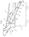
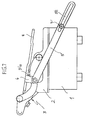
- FIGS. 1 and 2 show a housing 1, which is fixed to the vehicle of the body of the front end of a motor vehicle, and which has a positionable housing cover 2.
- a protective device for actively setting up the front hood is housed.
- This protective device typically consists of a sensor-controlled releasable spring memory with corresponding positioning devices 1 a, for example in the form of a pair of scissors or a telescope, in order to set the housing cover 2 in case of danger by a predetermined stroke.
- all protection devices can be used insofar.
- the housing cover 2 is simultaneously designed as a hinge carrier, i. On it, a hinge assembly 3 is attached to the body side for the usual pivoting of the front hood of the motor vehicle.
- a 4-hinge hinge with the hinge rods 3 a, 3 b is shown, which are hinged at one end to the hinge support 2 rotatably, and whose other ends on a hinge flange 4, which serves to receive the front hood, or are pivotally coupled to its laterally parked part.
- hinge arrangements In principle, differently constructed hinge arrangements can also be used.
- the invention is independent of this.
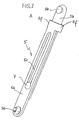
- a tension rod is provided, which is formed by a two-part pull tab 5 with slot, and which is shown in detail in Fig. 2 as a single component.
- the pull-tab 5 has two, each consisting of a strip-shaped flat material flap parts 5 a, 5 b, of which the lower flap portion 5 a has a slot 5 c and is hinged body-fixed with a pin 5 d, and of which the upper flap portion 5 b is pivotally articulated by means of a pin 5 e at a mounting bracket 6 of the hinge flange 4.
- a bolt 7 or rivet, screw or the like By means of a bolt 7 or rivet, screw or the like, which penetrates the slot 5 c, the upper flap portion 5 b is slidably received in the lower flap portion 5 a.
- Two folds 5 f at the upper end of the lower flap portion 5 a include the upper flap portion 5 b, i. Keep both flap parts centered together, so that a linear, axial displacement of the flap parts 5 a, 5 b is guaranteed to each other.
- the illustrated reversing device in the form of the pull tab 5 shown operates as follows:
- the pull tab 5 In the basic position of Fig. 1, i. when the hood is closed, but also during normal opening of the hood for service purposes according to Fig. 4, the pull tab 5 has no function and is axially and about the axis 5 d and 5 e freely movable.
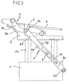
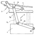
- the hinge carrier 2 together with the hinge arrangement 3 and thus also the front hood is set up in the rear part by means of the positioning elements 1a from the basic position according to FIG. This condition is shown in FIG.
- the pull tab 5 is pulled out without delay by a predetermined distance and the axes 5 d and 5 e ensure a free mobility that does not affect the installation process.
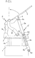
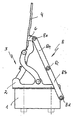
- the bonnet lock is opened and the bonnet initially opened so long until the pull tab 5 is extended to its maximum length, i. the bolt 7 comes to rest with the upper end of the elongated hole 5 c. This state is shown in FIG. 5.
- the actual reversing process begins by the front hood is further set up using a higher manual force in the arrow direction of FIG. 5 until an approximately 90 ° position shown in FIG. 6, the so-called workshop position is reached.
- a hinged hinge flange 4 at the pivot point 5 'a one-piece pull tab 5 'of FIG. 7 which has a slot 5' c, which is guided in a body-fixed, for example on the erection housing 1, bolt 7 '.
- the function is the same as that of the double lug.
- the reversing phase occurs as soon as the lower end of the elongated hole 5 'c comes to the stop on the body-fixed bolt 7'.
- double lug 5 with slot as a delay pull-out pull rod can also be a double lug in kinked design, i. be provided in the form of two pivotally interconnected tabs.
- Figures 8-12 show such an embodiment.
- the parts identical with the embodiment according to FIGS. 1 to 6 are provided with the same reference numerals.
- the alternative tension rod in the form of a double strap 8 consists of two tabs 8 a, 8 b, which are rotatably connected to each other in the pivot point 8 c by conventional means (bolts, rivet, screw, etc).
- the free end of the lower flap 8 b is pivotally mounted on the body at the fulcrum 8 d and the free end of the upper flap 8 a is pivoted at the pivot point 8 e hinged to the hinge flange 4 and the associated mounting bracket 6.
- the double lug 8 acts analogous to the double lug 5 in Figures 1-6 as a rigid articulated arm with a new fulcrum 8 e, so that the hinge 3 is depressed with the hinge support 2 (Fig. 11) until reaching the 90 ° -Werkstatt ein (Fig. 12) of the hinge support 2 has been completely reversed again, ie the system after closing the bonnet back to the basic position of FIG. 8 has reached.
- a telescopic arrangement is conceivable in which, for example, a round rod with a piston-like approach in a cylindrical housing is accommodated without delay axially displaceable, the round rod with its free end on the hinge flange (or the front hood) and the cylinder-like housing is articulated rotatably on the body side.
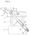
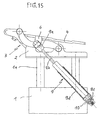
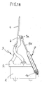
- Figures 13-18 show a further embodiment of a tension rod in the form of an extendable gas spring, which, however, has a releasable lock, so that it unlike the cited prior art retractable without delay and does not dampen the Aufstellvorgang the protective device.
- Figures 13-18 show as a reverse train rod a conventional gas spring 9, as it is used as a comfort opening aid for tailgates, bonnets, etc. on a large scale. Their structure and mode of action is known and therefore need not be explained here.
- the gas spring 9 is fixed with its upper end 9 a, but rotatably mounted on the front hood bearing hinge flange 4. The lower end is connected via a detachable in the event of a crash connection, in the example shown, a ball lock 10, body fixed, but rotatably articulated.
- Such releasable connections including the ball lock, are known from the art of roll bars and therefore need not be further explained here.
- the ball lock is known from DE 37 32 561 C2, which is hereby incorporated by reference into the subject of the disclosure.
- This detachable connection makes the use of a gas spring as a reverse pull rod in practice only possible.
- a conventional gas spring has the decisive disadvantage of its inertia for the present purpose. You would in a sudden lineup of the front hood within the required, in the ms range lying set-up time have a braking effect.
- the decoupling of the hydraulic pneumatic part of the gas spring makes it possible to comply with the required erection time.
- Fig. 13 shows the position of the gas spring with lock in the ground state, i. the bonnet is closed and the accident protection device is not installed.
- the hinge carrier 2 as shown in Fig. 14, set up by the predetermined stroke.
- the fixation of the piston rod 9 b is released in the gas spring by releasing the pin 9 c attached to it, i. Gas spring and associated guide tube 9 d are pulled apart.
- the gas spring has no frictional connection with the body and thus can not adversely affect the HIC value, a measure of the injury severity.
Landscapes
- Engineering & Computer Science (AREA)
- Mechanical Engineering (AREA)
- Superstructure Of Vehicle (AREA)
- Fittings On The Vehicle Exterior For Carrying Loads, And Devices For Holding Or Mounting Articles (AREA)
- Lighting Device Outwards From Vehicle And Optical Signal (AREA)
- Soil Working Implements (AREA)
Applications Claiming Priority (3)
| Application Number | Priority Date | Filing Date | Title |
|---|---|---|---|
| DE10323118 | 2003-05-22 | ||
| DE10323118A DE10323118B4 (de) | 2003-05-22 | 2003-05-22 | Einrichtung zum manuellen Reversieren einer Vorrichtung zum Schutz von Personen bei einem Frontalaufprall auf ein Kraftfahrzeug |
| PCT/EP2004/002686 WO2004103780A1 (de) | 2003-05-22 | 2004-03-16 | Einrichtung zum manuellen reversieren einer vorrichtung zum schutz von personen bei einem frontalaufprall auf ein kraftfahrzeug |
Publications (2)
| Publication Number | Publication Date |
|---|---|
| EP1560733A1 EP1560733A1 (de) | 2005-08-10 |
| EP1560733B1 true EP1560733B1 (de) | 2006-06-14 |
Family
ID=33461838
Family Applications (1)
| Application Number | Title | Priority Date | Filing Date |
|---|---|---|---|
| EP04720857A Expired - Lifetime EP1560733B1 (de) | 2003-05-22 | 2004-03-16 | Einrichtung zum manuellen reversieren einer vorrichtung zum schutz von personen bei einem frontalaufprall auf ein kraftfahrzeug |
Country Status (6)
| Country | Link |
|---|---|
| EP (1) | EP1560733B1 (es) |
| JP (1) | JP2007501161A (es) |
| AT (1) | ATE329800T1 (es) |
| DE (2) | DE10323118B4 (es) |
| ES (1) | ES2265142T3 (es) |
| WO (1) | WO2004103780A1 (es) |
Cited By (1)
| Publication number | Priority date | Publication date | Assignee | Title |
|---|---|---|---|---|
| DE102010021687B4 (de) | 2010-05-27 | 2022-09-08 | Stabilus Gmbh | Gasfeder und Motorhaubeneinheit mit der Gasfeder |
Families Citing this family (19)
| Publication number | Priority date | Publication date | Assignee | Title |
|---|---|---|---|---|
| DE10325351B4 (de) * | 2003-06-05 | 2009-07-02 | Daimler Ag | Fronthaubenanordnung |
| DE102004037320A1 (de) * | 2004-08-02 | 2006-03-16 | Trw Automotive Gmbh | Vorrichtung zum Anheben eines Karosserieteils eines Kraftfahrzeugs und Verfahren zum Betreiben einer solchen Vorrichtung |
| DE102005031024B4 (de) * | 2005-07-02 | 2007-09-27 | Daimlerchrysler Ag | Vorrichtung zum Aufstellen der Fronthaube eines Kraftfahrzeuges im Haubenscharnierbereich bei einem drohenden Personenaufprall mit einer Einrichtung zum Reversieren der aufgestellten Fronthaube |
| DE102005037684B4 (de) * | 2005-08-10 | 2011-07-21 | Bayerische Motoren Werke Aktiengesellschaft, 80809 | Frontklappenanordnung mit einer passiven Verformungseinrichtung |
| DE102005039908B4 (de) | 2005-08-24 | 2007-08-30 | Bayerische Motoren Werke Ag | Vorrichtung zum Aufstellen der Fronthaube eines Kraftfahrzeuges bei einem drohenden Personenaufprall mit einer Einrichtung zum Reversieren der aufgestellten Fronthaube |
| CA2518682A1 (en) * | 2005-09-09 | 2007-03-09 | Multimatic Inc. | Pedestrian protection hood hinge |
| FR2896216B1 (fr) * | 2006-01-19 | 2008-04-11 | Peugeot Citroen Automobiles Sa | Dispositif de protection des pietons en cas de choc frontal avec un vehicule automobile et vehicule automobile equipe d'un tel dispositif de protection des pietons. |
| DE102007009096A1 (de) | 2007-02-24 | 2008-08-28 | Suspa Holding Gmbh | Kraftspeicher und Verwendung des Kraftspeichers in einer Fußgänger-Schutz-Vorrichtung an Kraftfahrzeugen |
| WO2009077083A2 (de) * | 2007-12-14 | 2009-06-25 | Thomas Magnete Gmbh | Reversierbares entriegelungssystem einer sicherheitsvorrichtung in kraftfahrzeugen |
| DE202009013216U1 (de) | 2009-02-11 | 2010-07-22 | Suspa Gmbh | Aktuator für Fußgängerschutzeinrichtung |
| DE102010029410A1 (de) | 2010-05-27 | 2011-12-01 | Bayerische Motoren Werke Aktiengesellschaft | Feder- und Dämpfer-Baueinheit |
| DE102010023285A1 (de) | 2010-06-10 | 2011-12-15 | Gm Global Technology Operations Llc (N.D.Ges.D. Staates Delaware) | Kraftfahrzeugkarosserie mit reversierbarer Haube |
| DE102013017457A1 (de) * | 2013-10-21 | 2015-04-23 | Audi Ag | Verstellvorrichtung für eine Frontklappe und zugehöriges Kraftfahrzeug |
| EP3184375B1 (en) * | 2015-12-22 | 2020-02-12 | Volvo Car Corporation | Hinge arrangement |
| DE102016103198B4 (de) | 2016-02-24 | 2021-08-19 | Dr. Ing. H.C. F. Porsche Aktiengesellschaft | Vorrichtung zum Anstellen einer frontseitigen Fahrzeughaube bei einem Frontaufprall einer Person |
| DE102016002524B3 (de) * | 2016-03-01 | 2017-06-22 | Audi Ag | Klappenscharnier für einer Frontklappe eines Fahrzeugs mit einem teleskopierbaren Lenkerhebel |
| DE102016002523B3 (de) * | 2016-03-01 | 2017-06-22 | Audi Ag | Klappenscharnier für eine Frontklappe eines Fahrzeugs mit einer verschiebbaren Lagerung eines Hubaktuators |
| DE102018125800A1 (de) | 2018-10-17 | 2020-04-23 | Brose Fahrzeugteile Se & Co. Kommanditgesellschaft, Bamberg | Antriebsanordnung für eine Klappe eines Kraftfahrzeugs |
| CN113639909B (zh) * | 2021-07-01 | 2023-06-06 | 东风柳州汽车有限公司 | 引擎盖拉脱力试验装置 |
Family Cites Families (9)
| Publication number | Priority date | Publication date | Assignee | Title |
|---|---|---|---|---|
| DE2814107A1 (de) * | 1978-04-01 | 1979-10-04 | Volkswagenwerk Ag | Sicherheitseinrichtung zum schutz von fussgaengern |
| DE2841315A1 (de) * | 1978-09-22 | 1980-04-10 | Volkswagenwerk Ag | Sicherheitseinrichtung zum schutz von fussgaengern |
| DE3732561A1 (de) * | 1987-09-26 | 1989-04-13 | Daimler Benz Ag | Verriegelbarer hydraulikzylinder |
| JPH09315266A (ja) * | 1996-05-31 | 1997-12-09 | Mitsubishi Motors Corp | 車両用フード装置 |
| DE19712961B4 (de) * | 1997-03-27 | 2009-07-09 | Bayerische Motoren Werke Aktiengesellschaft | Verfahren betreffend eine Einrichtung zum Anheben einer Frontklappe an einem Fahrzeug |
| US6293362B1 (en) * | 1999-07-09 | 2001-09-25 | Honda Giken Kogyo Kabushiki Kaisha | Vehicle hood apparatus |
| DE10111096A1 (de) * | 2001-03-08 | 2002-09-26 | Bayerische Motoren Werke Ag | Anordnung einer Frontklappe an einem Fahrzeug |
| DE10116716A1 (de) * | 2001-04-04 | 2002-10-10 | Volkswagen Ag | Scharniereinrichtung für eine anhebbare Fronthaube an einem Fahrzeug |
| DE102004002213B4 (de) * | 2003-01-22 | 2013-04-04 | Scherdel Innotec Forschungs- Und Entwicklungs-Gmbh | Fußgängerschutz-Aktuator mit Rückstelleinrichtung |
-
2003
- 2003-05-22 DE DE10323118A patent/DE10323118B4/de not_active Expired - Fee Related
-
2004
- 2004-03-16 ES ES04720857T patent/ES2265142T3/es not_active Expired - Lifetime
- 2004-03-16 AT AT04720857T patent/ATE329800T1/de not_active IP Right Cessation
- 2004-03-16 DE DE502004000767T patent/DE502004000767D1/de not_active Expired - Lifetime
- 2004-03-16 WO PCT/EP2004/002686 patent/WO2004103780A1/de active IP Right Grant
- 2004-03-16 JP JP2006529664A patent/JP2007501161A/ja active Pending
- 2004-03-16 EP EP04720857A patent/EP1560733B1/de not_active Expired - Lifetime
Cited By (1)
| Publication number | Priority date | Publication date | Assignee | Title |
|---|---|---|---|---|
| DE102010021687B4 (de) | 2010-05-27 | 2022-09-08 | Stabilus Gmbh | Gasfeder und Motorhaubeneinheit mit der Gasfeder |
Also Published As
| Publication number | Publication date |
|---|---|
| DE10323118B4 (de) | 2011-07-21 |
| DE10323118A1 (de) | 2004-12-23 |
| EP1560733A1 (de) | 2005-08-10 |
| DE502004000767D1 (de) | 2006-07-27 |
| ES2265142T3 (es) | 2007-02-01 |
| JP2007501161A (ja) | 2007-01-25 |
| ATE329800T1 (de) | 2006-07-15 |
| WO2004103780A1 (de) | 2004-12-02 |
Similar Documents
| Publication | Publication Date | Title |
|---|---|---|
| EP1560733B1 (de) | Einrichtung zum manuellen reversieren einer vorrichtung zum schutz von personen bei einem frontalaufprall auf ein kraftfahrzeug | |
| EP1178916B1 (de) | Fronthaubenanordnung | |
| DE10066268B4 (de) | Sicherheitssystem für ein Kraftfahrzeug | |
| EP1178918B1 (de) | Fronthaubenanordnung | |
| DE102004062105B4 (de) | Vorrichtung zum Schutz von Personen bei einem Frontalaufprall auf ein Kraftfahrzeug durch aktives Aufstellen dessen Fronthaube | |
| EP1178917B1 (de) | Fronthaubenanordnung | |
| EP3172091B1 (de) | Fahrzeug mit einer fussgängerschutzvorrichtung | |
| WO2004016478A1 (de) | Vorrichtung zum schutz einer sich im aussenbereich eines kraftfahrzeugs befindlichen person | |
| DE10128967C1 (de) | Sicherheitseinrichtung eines Kraftfahrzeugs | |
| EP1882617A2 (de) | Vorrichtung zum Aufstellen der Fronthaube eines Kraftfahrzeuges bei einem drohenden Personenaufprall | |
| WO2000069703A1 (de) | Fronthaubenanordnung | |
| DE102005039908B4 (de) | Vorrichtung zum Aufstellen der Fronthaube eines Kraftfahrzeuges bei einem drohenden Personenaufprall mit einer Einrichtung zum Reversieren der aufgestellten Fronthaube | |
| EP1737709B1 (de) | Vorrichtung zum schutz von personen bei einem frontalaufprall auf ein kraftfahrzeug durch aufstellen dessen fronthaube | |
| EP2862757B1 (de) | Verstellvorrichtung für eine Frontklappe und zugehöriges Kraftfahrzeug | |
| DE102005054039B4 (de) | Aufstellbare Schutzvorrichtung in Kraftfahrzeugen zum Personenschutz mit einem Federantrieb | |
| DE10326404B4 (de) | Vorrichtung zum Schutz von Personen bei einem Frontaufprall auf ein Kraftfahrzeug | |
| DE102007041555B4 (de) | Vorrichtung zum Aufstellen der Fronthaube eines Kraftfahrzeuges bei einem drohenden Personenaufprall | |
| DE10350533B4 (de) | Vorrichtung zum Schutz von Personen bei einem Frontalaufprall auf ein Kraftfahrzeug durch aktives Aufstellen dessen Fronthaube | |
| EP1293416A2 (de) | Anordnung einer Frontklappe an einem Fahrzeug | |
| DE202008007671U1 (de) | Vorderbau für ein Kraftfahrzeug | |
| EP1562799B9 (de) | Einrichtung zum reversieren einer zum unfallschutz sensorgesteuert aktiv aufgestellten fronthaube eines kraftfahrzeuges | |
| DE19948460A1 (de) | Fronthaubenanordnung | |
| DE102007034584B4 (de) | Sicherheitseinrichtung an einem Fahrzeug, insbesondere an einem Kraftfahrzeug | |
| DE102004055405A1 (de) | Überrollschutz für Cabriolets | |
| DE19948461A1 (de) | Fronthaubenanordnung |
Legal Events
| Date | Code | Title | Description |
|---|---|---|---|
| PUAI | Public reference made under article 153(3) epc to a published international application that has entered the european phase |
Free format text: ORIGINAL CODE: 0009012 |
|
| 17P | Request for examination filed |
Effective date: 20050609 |
|
| AK | Designated contracting states |
Kind code of ref document: A1 Designated state(s): AT BE BG CH CY CZ DE DK EE ES FI FR GB GR HU IE IT LI LU MC NL PL PT RO SE SI SK TR |
|
| AX | Request for extension of the european patent |
Extension state: AL LT LV MK |
|
| GRAP | Despatch of communication of intention to grant a patent |
Free format text: ORIGINAL CODE: EPIDOSNIGR1 |
|
| GRAS | Grant fee paid |
Free format text: ORIGINAL CODE: EPIDOSNIGR3 |
|
| GRAA | (expected) grant |
Free format text: ORIGINAL CODE: 0009210 |
|
| DAX | Request for extension of the european patent (deleted) | ||
| AK | Designated contracting states |
Kind code of ref document: B1 Designated state(s): AT BE BG CH CY CZ DE DK EE ES FI FR GB GR HU IE IT LI LU MC NL PL PT RO SE SI SK TR |
|
| PG25 | Lapsed in a contracting state [announced via postgrant information from national office to epo] |
Ref country code: IT Free format text: LAPSE BECAUSE OF FAILURE TO SUBMIT A TRANSLATION OF THE DESCRIPTION OR TO PAY THE FEE WITHIN THE PRESCRIBED TIME-LIMIT;WARNING: LAPSES OF ITALIAN PATENTS WITH EFFECTIVE DATE BEFORE 2007 MAY HAVE OCCURRED AT ANY TIME BEFORE 2007. THE CORRECT EFFECTIVE DATE MAY BE DIFFERENT FROM THE ONE RECORDED. Effective date: 20060614 Ref country code: FI Free format text: LAPSE BECAUSE OF FAILURE TO SUBMIT A TRANSLATION OF THE DESCRIPTION OR TO PAY THE FEE WITHIN THE PRESCRIBED TIME-LIMIT Effective date: 20060614 Ref country code: CZ Free format text: LAPSE BECAUSE OF FAILURE TO SUBMIT A TRANSLATION OF THE DESCRIPTION OR TO PAY THE FEE WITHIN THE PRESCRIBED TIME-LIMIT Effective date: 20060614 Ref country code: SI Free format text: LAPSE BECAUSE OF FAILURE TO SUBMIT A TRANSLATION OF THE DESCRIPTION OR TO PAY THE FEE WITHIN THE PRESCRIBED TIME-LIMIT Effective date: 20060614 Ref country code: RO Free format text: LAPSE BECAUSE OF FAILURE TO SUBMIT A TRANSLATION OF THE DESCRIPTION OR TO PAY THE FEE WITHIN THE PRESCRIBED TIME-LIMIT Effective date: 20060614 Ref country code: SK Free format text: LAPSE BECAUSE OF FAILURE TO SUBMIT A TRANSLATION OF THE DESCRIPTION OR TO PAY THE FEE WITHIN THE PRESCRIBED TIME-LIMIT Effective date: 20060614 Ref country code: IE Free format text: LAPSE BECAUSE OF FAILURE TO SUBMIT A TRANSLATION OF THE DESCRIPTION OR TO PAY THE FEE WITHIN THE PRESCRIBED TIME-LIMIT Effective date: 20060614 Ref country code: NL Free format text: LAPSE BECAUSE OF FAILURE TO SUBMIT A TRANSLATION OF THE DESCRIPTION OR TO PAY THE FEE WITHIN THE PRESCRIBED TIME-LIMIT Effective date: 20060614 Ref country code: PL Free format text: LAPSE BECAUSE OF FAILURE TO SUBMIT A TRANSLATION OF THE DESCRIPTION OR TO PAY THE FEE WITHIN THE PRESCRIBED TIME-LIMIT Effective date: 20060614 |
|
| REG | Reference to a national code |
Ref country code: GB Ref legal event code: FG4D Free format text: NOT ENGLISH |
|
| REG | Reference to a national code |
Ref country code: CH Ref legal event code: EP |
|
| REG | Reference to a national code |
Ref country code: IE Ref legal event code: FG4D Free format text: LANGUAGE OF EP DOCUMENT: GERMAN |
|
| REF | Corresponds to: |
Ref document number: 502004000767 Country of ref document: DE Date of ref document: 20060727 Kind code of ref document: P |
|
| PG25 | Lapsed in a contracting state [announced via postgrant information from national office to epo] |
Ref country code: DK Free format text: LAPSE BECAUSE OF FAILURE TO SUBMIT A TRANSLATION OF THE DESCRIPTION OR TO PAY THE FEE WITHIN THE PRESCRIBED TIME-LIMIT Effective date: 20060914 Ref country code: SE Free format text: LAPSE BECAUSE OF FAILURE TO SUBMIT A TRANSLATION OF THE DESCRIPTION OR TO PAY THE FEE WITHIN THE PRESCRIBED TIME-LIMIT Effective date: 20060914 |
|
| GBT | Gb: translation of ep patent filed (gb section 77(6)(a)/1977) |
Effective date: 20060913 |
|
| PG25 | Lapsed in a contracting state [announced via postgrant information from national office to epo] |
Ref country code: PT Free format text: LAPSE BECAUSE OF FAILURE TO SUBMIT A TRANSLATION OF THE DESCRIPTION OR TO PAY THE FEE WITHIN THE PRESCRIBED TIME-LIMIT Effective date: 20061114 |
|
| NLV1 | Nl: lapsed or annulled due to failure to fulfill the requirements of art. 29p and 29m of the patents act | ||
| ET | Fr: translation filed | ||
| REG | Reference to a national code |
Ref country code: ES Ref legal event code: FG2A Ref document number: 2265142 Country of ref document: ES Kind code of ref document: T3 |
|
| REG | Reference to a national code |
Ref country code: IE Ref legal event code: FD4D |
|
| PLBE | No opposition filed within time limit |
Free format text: ORIGINAL CODE: 0009261 |
|
| STAA | Information on the status of an ep patent application or granted ep patent |
Free format text: STATUS: NO OPPOSITION FILED WITHIN TIME LIMIT |
|
| 26N | No opposition filed |
Effective date: 20070315 |
|
| BERE | Be: lapsed |
Owner name: ISE INNOMOTIVE SYSTEMS EUROPE G.M.B.H. Effective date: 20070331 |
|
| PG25 | Lapsed in a contracting state [announced via postgrant information from national office to epo] |
Ref country code: BE Free format text: LAPSE BECAUSE OF NON-PAYMENT OF DUE FEES Effective date: 20070331 |
|
| PG25 | Lapsed in a contracting state [announced via postgrant information from national office to epo] |
Ref country code: MC Free format text: LAPSE BECAUSE OF NON-PAYMENT OF DUE FEES Effective date: 20070331 |
|
| PG25 | Lapsed in a contracting state [announced via postgrant information from national office to epo] |
Ref country code: GR Free format text: LAPSE BECAUSE OF FAILURE TO SUBMIT A TRANSLATION OF THE DESCRIPTION OR TO PAY THE FEE WITHIN THE PRESCRIBED TIME-LIMIT Effective date: 20060915 |
|
| PGFP | Annual fee paid to national office [announced via postgrant information from national office to epo] |
Ref country code: ES Payment date: 20080326 Year of fee payment: 5 |
|
| PG25 | Lapsed in a contracting state [announced via postgrant information from national office to epo] |
Ref country code: BG Free format text: LAPSE BECAUSE OF FAILURE TO SUBMIT A TRANSLATION OF THE DESCRIPTION OR TO PAY THE FEE WITHIN THE PRESCRIBED TIME-LIMIT Effective date: 20060914 Ref country code: AT Free format text: LAPSE BECAUSE OF NON-PAYMENT OF DUE FEES Effective date: 20070316 |
|
| PG25 | Lapsed in a contracting state [announced via postgrant information from national office to epo] |
Ref country code: EE Free format text: LAPSE BECAUSE OF FAILURE TO SUBMIT A TRANSLATION OF THE DESCRIPTION OR TO PAY THE FEE WITHIN THE PRESCRIBED TIME-LIMIT Effective date: 20060614 |
|
| PGRI | Patent reinstated in contracting state [announced from national office to epo] |
Ref country code: IT Effective date: 20080601 |
|
| REG | Reference to a national code |
Ref country code: CH Ref legal event code: PL |
|
| PG25 | Lapsed in a contracting state [announced via postgrant information from national office to epo] |
Ref country code: LI Free format text: LAPSE BECAUSE OF NON-PAYMENT OF DUE FEES Effective date: 20080331 Ref country code: CH Free format text: LAPSE BECAUSE OF NON-PAYMENT OF DUE FEES Effective date: 20080331 |
|
| PGFP | Annual fee paid to national office [announced via postgrant information from national office to epo] |
Ref country code: GB Payment date: 20090324 Year of fee payment: 6 |
|
| PG25 | Lapsed in a contracting state [announced via postgrant information from national office to epo] |
Ref country code: CY Free format text: LAPSE BECAUSE OF FAILURE TO SUBMIT A TRANSLATION OF THE DESCRIPTION OR TO PAY THE FEE WITHIN THE PRESCRIBED TIME-LIMIT Effective date: 20060614 Ref country code: LU Free format text: LAPSE BECAUSE OF NON-PAYMENT OF DUE FEES Effective date: 20070316 |
|
| PGFP | Annual fee paid to national office [announced via postgrant information from national office to epo] |
Ref country code: IT Payment date: 20090330 Year of fee payment: 6 |
|
| PG25 | Lapsed in a contracting state [announced via postgrant information from national office to epo] |
Ref country code: HU Free format text: LAPSE BECAUSE OF FAILURE TO SUBMIT A TRANSLATION OF THE DESCRIPTION OR TO PAY THE FEE WITHIN THE PRESCRIBED TIME-LIMIT Effective date: 20061215 Ref country code: TR Free format text: LAPSE BECAUSE OF FAILURE TO SUBMIT A TRANSLATION OF THE DESCRIPTION OR TO PAY THE FEE WITHIN THE PRESCRIBED TIME-LIMIT Effective date: 20060614 |
|
| PGFP | Annual fee paid to national office [announced via postgrant information from national office to epo] |
Ref country code: FR Payment date: 20090318 Year of fee payment: 6 |
|
| REG | Reference to a national code |
Ref country code: ES Ref legal event code: FD2A Effective date: 20090317 |
|
| PG25 | Lapsed in a contracting state [announced via postgrant information from national office to epo] |
Ref country code: ES Free format text: LAPSE BECAUSE OF NON-PAYMENT OF DUE FEES Effective date: 20090317 |
|
| GBPC | Gb: european patent ceased through non-payment of renewal fee |
Effective date: 20100316 |
|
| REG | Reference to a national code |
Ref country code: FR Ref legal event code: ST Effective date: 20101130 |
|
| PG25 | Lapsed in a contracting state [announced via postgrant information from national office to epo] |
Ref country code: FR Free format text: LAPSE BECAUSE OF NON-PAYMENT OF DUE FEES Effective date: 20100331 |
|
| PG25 | Lapsed in a contracting state [announced via postgrant information from national office to epo] |
Ref country code: IT Free format text: LAPSE BECAUSE OF NON-PAYMENT OF DUE FEES Effective date: 20100316 Ref country code: GB Free format text: LAPSE BECAUSE OF NON-PAYMENT OF DUE FEES Effective date: 20100316 |
|
| REG | Reference to a national code |
Ref country code: DE Ref legal event code: R081 Ref document number: 502004000767 Country of ref document: DE Owner name: BAYERISCHE MOTOREN WERKE AKTIENGESELLSCHAFT, DE Free format text: FORMER OWNER: ISE AUTOMOTIVE GMBH, 51702 BERGNEUSTADT, DE Effective date: 20110420 |
|
| PGFP | Annual fee paid to national office [announced via postgrant information from national office to epo] |
Ref country code: DE Payment date: 20110504 Year of fee payment: 8 |
|
| REG | Reference to a national code |
Ref country code: DE Ref legal event code: R119 Ref document number: 502004000767 Country of ref document: DE Effective date: 20121002 |
|
| PG25 | Lapsed in a contracting state [announced via postgrant information from national office to epo] |
Ref country code: DE Free format text: LAPSE BECAUSE OF NON-PAYMENT OF DUE FEES Effective date: 20121002 |