EP1560426A1 - Bildeingabeeinrichtung - Google Patents
Bildeingabeeinrichtung Download PDFInfo
- Publication number
- EP1560426A1 EP1560426A1 EP03775815A EP03775815A EP1560426A1 EP 1560426 A1 EP1560426 A1 EP 1560426A1 EP 03775815 A EP03775815 A EP 03775815A EP 03775815 A EP03775815 A EP 03775815A EP 1560426 A1 EP1560426 A1 EP 1560426A1
- Authority
- EP
- European Patent Office
- Prior art keywords
- micro
- lens
- light detecting
- image
- input apparatus
- Prior art date
- Legal status (The legal status is an assumption and is not a legal conclusion. Google has not performed a legal analysis and makes no representation as to the accuracy of the status listed.)
- Granted
Links
Images






Classifications
-
- G—PHYSICS
- G02—OPTICS
- G02B—OPTICAL ELEMENTS, SYSTEMS OR APPARATUS
- G02B3/00—Simple or compound lenses
- G02B3/0006—Arrays
- G02B3/0037—Arrays characterized by the distribution or form of lenses
- G02B3/0056—Arrays characterized by the distribution or form of lenses arranged along two different directions in a plane, e.g. honeycomb arrangement of lenses
-
- H—ELECTRICITY
- H04—ELECTRIC COMMUNICATION TECHNIQUE
- H04N—PICTORIAL COMMUNICATION, e.g. TELEVISION
- H04N23/00—Cameras or camera modules comprising electronic image sensors; Control thereof
- H04N23/50—Constructional details
- H04N23/54—Mounting of pick-up tubes, electronic image sensors, deviation or focusing coils
-
- H—ELECTRICITY
- H04—ELECTRIC COMMUNICATION TECHNIQUE
- H04N—PICTORIAL COMMUNICATION, e.g. TELEVISION
- H04N23/00—Cameras or camera modules comprising electronic image sensors; Control thereof
- H04N23/80—Camera processing pipelines; Components thereof
-
- H—ELECTRICITY
- H04—ELECTRIC COMMUNICATION TECHNIQUE
- H04N—PICTORIAL COMMUNICATION, e.g. TELEVISION
- H04N25/00—Circuitry of solid-state image sensors [SSIS]; Control thereof
- H04N25/10—Circuitry of solid-state image sensors [SSIS]; Control thereof for transforming different wavelengths into image signals
- H04N25/11—Arrangement of colour filter arrays [CFA]; Filter mosaics
- H04N25/13—Arrangement of colour filter arrays [CFA]; Filter mosaics characterised by the spectral characteristics of the filter elements
- H04N25/134—Arrangement of colour filter arrays [CFA]; Filter mosaics characterised by the spectral characteristics of the filter elements based on three different wavelength filter elements
-
- H—ELECTRICITY
- H04—ELECTRIC COMMUNICATION TECHNIQUE
- H04N—PICTORIAL COMMUNICATION, e.g. TELEVISION
- H04N25/00—Circuitry of solid-state image sensors [SSIS]; Control thereof
- H04N25/10—Circuitry of solid-state image sensors [SSIS]; Control thereof for transforming different wavelengths into image signals
- H04N25/11—Arrangement of colour filter arrays [CFA]; Filter mosaics
- H04N25/13—Arrangement of colour filter arrays [CFA]; Filter mosaics characterised by the spectral characteristics of the filter elements
- H04N25/135—Arrangement of colour filter arrays [CFA]; Filter mosaics characterised by the spectral characteristics of the filter elements based on four or more different wavelength filter elements
- H04N25/136—Arrangement of colour filter arrays [CFA]; Filter mosaics characterised by the spectral characteristics of the filter elements based on four or more different wavelength filter elements using complementary colours
Definitions
- the present invention relates to an image input apparatus which can reconfigure a single, high-resolution object image from a plurality of low-resolution, object reduced images obtained by a plurality of micro-lens, wherein a high-resolution image of the object image can be obtained even if the imaging distance is long (infinitely long, for example), and the object image can be realized in colors.
- image input devices such as digital cameras and video cameras for obtaining the image by a single optical system facing the subject, have already been in use as the image reader which allows effectively obtaining various kinds of high-quality image information.
- the above-mentioned image input apparatus is schematically comprising a micro-lens array having a plurality of micro-lens and planate light detecting elements facing the micro-lens array, wherein a plurality of low-resolution reduced images are focused in the prescribed region on the said light detecting element by the said micro-lens array, and a single object image is reconfigured by signal processing of said reduced object image.
- the image input apparatus in spite of being small and thin compared with the apparatus comprising a single optical system, realizes bright optical system and even makes obtained (reconfigured) object image (hereinafter referred to as "reconfigured image”) as highly fine.
- the image input apparatus comprising the said compound-eye mechanism is characterized by imaging the subject from different viewpoints by having parallax between the said micro-lenses.
- the above-mentioned character (parallax between the micro-lenses) enables object reduced images, which are focused on the prescribed position on the said light detecting element, to form the different images on each micro-lens (images which include different image information), and as a result, a single reconfigured image obtained by rearranging the said object reduced images can be obtained as a highly fine image (contains more image information).
- the image information obtained by image input apparatus is preferably recreated by the real colors (colorizing) of the subject. Consequently, as the technology of colorizing the reconfigured image obtained by the image input apparatus comprising the above-mentioned structure, the arrangement of color filters to every micro-lens was suggested, and has been applied for a patent under Japanese Patent Application No. 2001-363117 by the present applicant. However, the technology for colorizing is not limited to the above-mentioned formula, and it is necessary and expected to develop another formula.
- the present image input apparatus has been invented considering the foregoing conditions, and the first object of this invention is to provide the image input apparatus which can reconfigure a single reconfigured image from a plurality of low-resolution, object reduced images focused on the prescribed region on the said light detecting elements by the micro-lens array, wherein a high-resolution, single reconfigured image of the subject can be obtained even if the distance between the subject and the said micro-lens array is long (infinitely long, for example).
- the second object is to provide the new formula, which can realize the colorizing of the reconfigured image.
- this invention provides an image input apparatus comprising a micro-lens array where a plurality of micro-lenses are arrayed and the light detecting element facing the said micro-lens array, wherein a single object image can be obtained by rearranging the image information of a plurality of object reduced images focused on the prescribed region on the light detecting element by each of the said micro-lens, and characterized in that the relative position between the said micro-lens and the prescribed region on the light detecting element, on which the object reduced image is focused as corresponding to the said micro-lens, are arranged so as to differ between each of the said micro-lenses.
- the object reduced images focused on the light detecting element can be differed at every micro-lenses, furthermore, the resolution of the reconfigured image obtained by the rearrangement of image information of the object reduced images can be increased.
- the said relative position can be shifted by (s/N - D/m) ⁇ s: pitch of light detecting element, N: number of micro-lens unit, D: pitch of micro-lens, m: magnification for the subject achieved by the micro-lens) sequentially along with the vertical direction and the horizontal direction on the said micro-lens array.
- the said relative position is adjusted corresponding to the distance to the subject (i.e. magnification)
- it is capable of focusing the different object reduced image on the light detecting element consistently, irrespective of the distance to the subject, and moreover, the resolution of the single reconfigured image obtained by the rearrangement of image information of the object reduced images can be increased. More details will hereinafter be described.
- the rearranging position of the object image, on which pixel information of the object reduced images are supposed to be rearranged is decided on the basis of the said relative position.
- the resolution of the said object image can be improved using the difference of the said object reduced images arising from the difference between the said relative positions by fixing the rearranged position of pixel information of the said reduced-images.
- the said rearranging position may be fixed to shift by (s/N + D/m) ⁇ (s): pitch of light detecting element, (N): number of micro-lens units, (D): pitch of micro-lens, m: magnification of micro-lens for the subject.
- m b/a (a: the distance between the micro-lens and the light detecting element, b: the distance between the micro-lens and the subject) ⁇ sequentially along with the vertical direction and the horizontal direction on the said micro-lens array.
- this invention comprises a light detecting element containing a plurality of light detecting cells, wherein the said light detecting cell is divided into multiple regions, and at the same time, a color filter is arranged on each of the said divided regions.
- the image input apparatus according to the embodiments of the present invention is embodied as indicated in Fig. 1.
- the image input apparatus (A) is comprised of a micro-lens array (1) arraying a plurality of micro-lenses (1a) in a grid-like pattern, a light detecting element (3) forming planimetrically a plurality of light detecting cells (3a), and a grid-shaped partition wall (2) arranged between micro-lens array (1) and light detecting element (3).
- micro-lens (1a) forms a signal-processing unit (U), which correspondingly comprises one grid of partition wall (2), as well as a plurality of light detecting cells (3a) included in the rectangular column (prescribed region).
- image input apparatus (A) with compound-eye is similar to the conventional image input apparatus in the basic concept of obtaining a single, high-resolution reconfigured image by focusing the object reduced images of the subject in respective unit (U), then reconfiguring the object reduced images.
- Micro-lens array (1) Number of lenses 10 x 10 Lens pitch 499 micron x 499 micron Focal length 1.0 mm Partition Wall (2) Partition wall pitch 499 micron Height of the Partition wall 1.0 mm Thickness of the Partition wall 39 micron Size of the opening of the Partition wall 460 micron x 460 micron Light detecting element (3) Number of pixels 500 x 500 Size of pixels 10 x 10 micron
- Fig. 2 is a plane view of micro-lens array (1), and indicates the arrangement example of the whole unit, which comprises (N) number of micro-lenses (1a) in both horizontal and vertical directions.
- Fig. 3 is a plane view of light detecting element (3), and indicates the arrangement example where each unit comprises (n) number of light detecting cells (3a) in both horizontal and vertical directions.
- the subject embodiment is characterized by arranging the relative position between light detecting cells (3a) and micro-lens (1a) differently in each unit (i.e. micro-lens (1a)).
- the relative position shift by s/N per unit sequentially in a vertical direction as well as a horizontal direction of micro-lenses (1a) arrangement.
- reconfigured image 1 the first signal of pixel in unit 1
- reconfigured image 2 the first signal of pixel in unit 2 : : reconfigured image N : the first signal of pixel in unit N reconfigured image N + 1 : the second signal of pixel in unit 1 reconfigured image N + 2 : the second signal of pixel in unit 2 : : reconfigured image 2N : the second signal of pixel in unit N reconfigured image 2N + 1 : the third signal of pixel in unit 1 : : reconfigured image 3N : the third signal of pixel in unit N reconfigured image 3N + 1 : the fourth signal of pixel in unit 1 : : reconfigured image (n-1) x (N) + 1 : the (n)th signal of pixel in unit 1 : : reconfigured image (n) x (N) : the
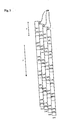
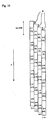
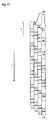
- the figure shows the case when the size of the reconfigured image is (n) x (s). Also, the number (1) to (24) shown respectively in the light detecting cells are coordinate y of the reconfigured image.
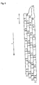
- light detecting cells (3a) are rearranged having shifting of D/m in addition to the case in Fig. 5, compared with the case when the subject is at infinity (indicated in Fig. 5).
- (D) is a pitch of each unit (D/m ⁇ s/N).
- Unit pitch (D) 499 micron
- Light detecting cell pitch (s) 10 micron
- Micro-lens focal distance (f) 1mm
- light detecting cells (3a) in the other 7 units can effect on the resolution of the reconfigured image.
- the resolution decreases only about 30 percent when focusing on the subject in short distance.
- the resolution can be considerably increased for the subject having the distance toward the image (b) long as infinite (as indicated in Fig. 5), and moreover, the degradation of resolution can be minor for the subject in close distance (as indicated in Fig. 6).
- This invention therefore is more applicable and convenient, compared with conventional systems capable of obtaining merely the reconfigured image in a certain appropriate distance (especially, in flyby distance other than infinite long distance), since being able to provide the image input apparatus which can be used, irrespective of the distance toward the image (b).
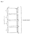
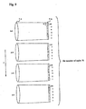
- the following described embodiment is characterized by that, as shown in Fig. 7, the relative position between micro-lens (1a) and light detecting cells (3a) in each unit is adjustable according to the distance toward the image (b), and adjustment responding to the distance toward the image (b) is not necessary when rearranging light detecting cells (3a).
- the pitch of the unit is (D)
- the number of the unit is (N)
- the pitch of the light detecting cell is (s)
- Fig. 8 also indicates a case when the size of the reconfigured image is (n) x (s).
- this invention is superior over the above embodiment in the feature of constantly obtaining image with highly fine resolution, irrespective of the distance toward the image (b), since the redundant information would not occur even if the distance toward the image (b) is not infinite.
- Figs. 12 and 13 are plain views of light detecting element (3) indicating the arrangement of light detecting cells (3a) per unit, and show the cases when arraying (n) number of light detecting cells (3a) both in the horizontal and the vertical directions.
- light detecting cells (3a) are divided into several regions (4 regions in the present embodiment), while the color filters are arranged in each of the divided regions.
- Fig. 12 indicates the case when primary color filters comprising Green(G), Red(R), and Blue(B) are applied.
- Color information including the primary colors: green, red, and blue, can be obtained by, like foregoing embodiments, having micro-lens (1a) arranged to have different relative position with light detecting element (3) which has the above-mentioned dividing structure, and by providing prescribed signal processing to the object reduced images obtained per color.
- green that has highest human visibility is applied to a plurality of regions.
- signal-to-noise ratio of green signal is improved, thereby achieving improvement of the image quality.
- Fig. 13 indicates the case when complementary color filters: Cyan(Cy), Yellow(Ye), Magenta(Mg), and Green(G) as four-color filter, are applied.
- This case also achieves obtaining the color information of green and red and blue by providing prescribed signal processing, same as the primary color filters.
- Each colors: (R), (G) and (B) can be decided from the obtained image information of (Cy), (Ye) and (Mg) by calculation, and moreover, (G) can be calculated from light detecting cells (3a) comprising filter (G).
- the object image is reconfigured in regard to Cyan(Cy), Yellow(Ye), Magenta(Mg) and Green(G), from which the three primary colors, i.e. green, red and blue, is obtained by calculation.
- the present embodiment finally enables colorizing of the final reconfigured image, and further, prevents increase of production cost for its simple structure of merely arranging the predetermined color filters to light detecting cells (3a).
- the present invention can obtain the object reduced images differing in each unit even if the distance between the image input apparatus (A) and the subject is long (infinitely long, for example), and thereby achieving a high resolution, reconfigured image that is reconfigured based on those object reduced images.
- the colorization of the reconfigured image can be realized with the simple structure of providing the predetermined color filters to the light detecting cells formed within the light detecting element in the image input apparatus.
Landscapes
- Physics & Mathematics (AREA)
- Engineering & Computer Science (AREA)
- Multimedia (AREA)
- Signal Processing (AREA)
- Spectroscopy & Molecular Physics (AREA)
- General Physics & Mathematics (AREA)
- Optics & Photonics (AREA)
- Image Input (AREA)
- Transforming Light Signals Into Electric Signals (AREA)
- Solid State Image Pick-Up Elements (AREA)
- Color Television Image Signal Generators (AREA)
- Studio Devices (AREA)
Applications Claiming Priority (3)
| Application Number | Priority Date | Filing Date | Title |
|---|---|---|---|
| JP2002310375 | 2002-10-25 | ||
| JP2002310375A JP4171786B2 (ja) | 2002-10-25 | 2002-10-25 | 画像入力装置 |
| PCT/JP2003/013617 WO2004039071A1 (ja) | 2002-10-25 | 2003-10-24 | 画像入力装置 |
Publications (3)
| Publication Number | Publication Date |
|---|---|
| EP1560426A1 true EP1560426A1 (de) | 2005-08-03 |
| EP1560426A4 EP1560426A4 (de) | 2010-12-22 |
| EP1560426B1 EP1560426B1 (de) | 2013-12-18 |
Family
ID=32171048
Family Applications (1)
| Application Number | Title | Priority Date | Filing Date |
|---|---|---|---|
| EP03775815.8A Expired - Lifetime EP1560426B1 (de) | 2002-10-25 | 2003-10-24 | Bildeingabeeinrichtung |
Country Status (4)
| Country | Link |
|---|---|
| US (1) | US7529383B2 (de) |
| EP (1) | EP1560426B1 (de) |
| JP (1) | JP4171786B2 (de) |
| WO (1) | WO2004039071A1 (de) |
Families Citing this family (95)
| Publication number | Priority date | Publication date | Assignee | Title |
|---|---|---|---|---|
| DE102004003013B3 (de) * | 2004-01-20 | 2005-06-02 | Fraunhofer-Gesellschaft zur Förderung der angewandten Forschung e.V. | Bilderfassungssystem und dessen Verwendung |
| WO2007092545A2 (en) * | 2006-02-07 | 2007-08-16 | The Board Of Trustees Of The Leland Stanford Junior University | Variable imaging arrangements and methods therefor |
| WO2006039486A2 (en) | 2004-10-01 | 2006-04-13 | The Board Of Trustees Of The Leland Stanford Junior University | Imaging arrangements and methods therefor |
| JP2007116208A (ja) | 2005-10-17 | 2007-05-10 | Funai Electric Co Ltd | 複眼撮像装置 |
| JP2007304525A (ja) * | 2006-05-15 | 2007-11-22 | Ricoh Co Ltd | 画像入力装置および電子機器および画像入力方法 |
| US7966560B2 (en) * | 2006-10-24 | 2011-06-21 | International Business Machines Corporation | Laying out web components using mounting and pooling functions |
| JP2008288449A (ja) * | 2007-05-18 | 2008-11-27 | Nippon Hoso Kyokai <Nhk> | 撮像装置 |
| US8019215B2 (en) * | 2007-08-06 | 2011-09-13 | Adobe Systems Incorporated | Method and apparatus for radiance capture by multiplexing in the frequency domain |
| JP2009206922A (ja) | 2008-02-28 | 2009-09-10 | Funai Electric Co Ltd | 複眼撮像装置 |
| EP4336447B1 (de) | 2008-05-20 | 2025-05-07 | Adeia Imaging LLC | Aufnahme und verarbeitung von bildern mittels monolithischer kamera anordnung mit heterogenem bildwandler |
| US11792538B2 (en) | 2008-05-20 | 2023-10-17 | Adeia Imaging Llc | Capturing and processing of images including occlusions focused on an image sensor by a lens stack array |
| US8866920B2 (en) | 2008-05-20 | 2014-10-21 | Pelican Imaging Corporation | Capturing and processing of images using monolithic camera array with heterogeneous imagers |
| US8244058B1 (en) * | 2008-05-30 | 2012-08-14 | Adobe Systems Incorporated | Method and apparatus for managing artifacts in frequency domain processing of light-field images |
| JP5105482B2 (ja) * | 2008-09-01 | 2012-12-26 | 船井電機株式会社 | 光学的条件設計方法及び複眼撮像装置 |
| US8189089B1 (en) | 2009-01-20 | 2012-05-29 | Adobe Systems Incorporated | Methods and apparatus for reducing plenoptic camera artifacts |
| US8300108B2 (en) | 2009-02-02 | 2012-10-30 | L-3 Communications Cincinnati Electronics Corporation | Multi-channel imaging devices comprising unit cells |
| US8358365B2 (en) | 2009-05-01 | 2013-01-22 | Samsung Electronics Co., Ltd. | Photo detecting device and image pickup device and method thereon |
| US8228417B1 (en) | 2009-07-15 | 2012-07-24 | Adobe Systems Incorporated | Focused plenoptic camera employing different apertures or filtering at different microlenses |
| WO2011063347A2 (en) | 2009-11-20 | 2011-05-26 | Pelican Imaging Corporation | Capturing and processing of images using monolithic camera array with heterogeneous imagers |
| US8558915B2 (en) | 2009-12-22 | 2013-10-15 | Samsung Electronics Co., Ltd. | Photographing apparatus and method |
| US8817015B2 (en) | 2010-03-03 | 2014-08-26 | Adobe Systems Incorporated | Methods, apparatus, and computer-readable storage media for depth-based rendering of focused plenoptic camera data |
| US20120012748A1 (en) | 2010-05-12 | 2012-01-19 | Pelican Imaging Corporation | Architectures for imager arrays and array cameras |
| US8724000B2 (en) | 2010-08-27 | 2014-05-13 | Adobe Systems Incorporated | Methods and apparatus for super-resolution in integral photography |
| US8665341B2 (en) | 2010-08-27 | 2014-03-04 | Adobe Systems Incorporated | Methods and apparatus for rendering output images with simulated artistic effects from focused plenoptic camera data |
| US8749694B2 (en) | 2010-08-27 | 2014-06-10 | Adobe Systems Incorporated | Methods and apparatus for rendering focused plenoptic camera data using super-resolved demosaicing |
| US8803918B2 (en) | 2010-08-27 | 2014-08-12 | Adobe Systems Incorporated | Methods and apparatus for calibrating focused plenoptic camera data |
| US20120147228A1 (en) * | 2010-12-14 | 2012-06-14 | Duparre Jacques | Imaging systems with optical crosstalk suppression structures |
| US8878950B2 (en) * | 2010-12-14 | 2014-11-04 | Pelican Imaging Corporation | Systems and methods for synthesizing high resolution images using super-resolution processes |
| US9030550B2 (en) | 2011-03-25 | 2015-05-12 | Adobe Systems Incorporated | Thin plenoptic cameras using solid immersion lenses |
| EP2708019B1 (de) | 2011-05-11 | 2019-10-16 | FotoNation Limited | Systeme und verfahren zum senden und empfangen von arraykamera-bilddaten |
| EP2726930A4 (de) | 2011-06-28 | 2015-03-04 | Pelican Imaging Corp | Optische anordnungen zur verwendung mit einer arraykamera |
| US20130265459A1 (en) | 2011-06-28 | 2013-10-10 | Pelican Imaging Corporation | Optical arrangements for use with an array camera |
| WO2013043751A1 (en) | 2011-09-19 | 2013-03-28 | Pelican Imaging Corporation | Systems and methods for controlling aliasing in images captured by an array camera for use in super resolution processing using pixel apertures |
| JP6140709B2 (ja) | 2011-09-28 | 2017-05-31 | ペリカン イメージング コーポレイション | 明視野画像ファイルを符号化および復号するためのシステムおよび方法 |
| WO2013126578A1 (en) | 2012-02-21 | 2013-08-29 | Pelican Imaging Corporation | Systems and methods for the manipulation of captured light field image data |
| US9210392B2 (en) * | 2012-05-01 | 2015-12-08 | Pelican Imaging Coporation | Camera modules patterned with pi filter groups |
| US9179126B2 (en) | 2012-06-01 | 2015-11-03 | Ostendo Technologies, Inc. | Spatio-temporal light field cameras |
| EP2873028A4 (de) | 2012-06-28 | 2016-05-25 | Pelican Imaging Corp | Systeme und verfahren zur erkennung defekter kamera-arrays, optischer arrays und sensoren |
| US20140002674A1 (en) | 2012-06-30 | 2014-01-02 | Pelican Imaging Corporation | Systems and Methods for Manufacturing Camera Modules Using Active Alignment of Lens Stack Arrays and Sensors |
| JP6218186B2 (ja) | 2012-08-07 | 2017-10-25 | 国立大学法人静岡大学 | 固体撮像装置 |
| EP3869797B1 (de) | 2012-08-21 | 2023-07-19 | Adeia Imaging LLC | Verfahren zur tiefenerkennung in mit array-kameras aufgenommenen bildern |
| US20140055632A1 (en) | 2012-08-23 | 2014-02-27 | Pelican Imaging Corporation | Feature based high resolution motion estimation from low resolution images captured using an array source |
| WO2014043641A1 (en) | 2012-09-14 | 2014-03-20 | Pelican Imaging Corporation | Systems and methods for correcting user identified artifacts in light field images |
| US20140092281A1 (en) | 2012-09-28 | 2014-04-03 | Pelican Imaging Corporation | Generating Images from Light Fields Utilizing Virtual Viewpoints |
| JP6120523B2 (ja) * | 2012-10-24 | 2017-04-26 | オリンパス株式会社 | 撮像素子及び撮像装置 |
| WO2014078443A1 (en) | 2012-11-13 | 2014-05-22 | Pelican Imaging Corporation | Systems and methods for array camera focal plane control |
| WO2014130849A1 (en) | 2013-02-21 | 2014-08-28 | Pelican Imaging Corporation | Generating compressed light field representation data |
| WO2014133974A1 (en) | 2013-02-24 | 2014-09-04 | Pelican Imaging Corporation | Thin form computational and modular array cameras |
| US9638883B1 (en) | 2013-03-04 | 2017-05-02 | Fotonation Cayman Limited | Passive alignment of array camera modules constructed from lens stack arrays and sensors based upon alignment information obtained during manufacture of array camera modules using an active alignment process |
| WO2014138695A1 (en) | 2013-03-08 | 2014-09-12 | Pelican Imaging Corporation | Systems and methods for measuring scene information while capturing images using array cameras |
| US8866912B2 (en) | 2013-03-10 | 2014-10-21 | Pelican Imaging Corporation | System and methods for calibration of an array camera using a single captured image |
| US9521416B1 (en) | 2013-03-11 | 2016-12-13 | Kip Peli P1 Lp | Systems and methods for image data compression |
| WO2014165244A1 (en) | 2013-03-13 | 2014-10-09 | Pelican Imaging Corporation | Systems and methods for synthesizing images from image data captured by an array camera using restricted depth of field depth maps in which depth estimation precision varies |
| WO2014164909A1 (en) | 2013-03-13 | 2014-10-09 | Pelican Imaging Corporation | Array camera architecture implementing quantum film sensors |
| US9106784B2 (en) | 2013-03-13 | 2015-08-11 | Pelican Imaging Corporation | Systems and methods for controlling aliasing in images captured by an array camera for use in super-resolution processing |
| WO2014164550A2 (en) | 2013-03-13 | 2014-10-09 | Pelican Imaging Corporation | System and methods for calibration of an array camera |
| WO2014159779A1 (en) | 2013-03-14 | 2014-10-02 | Pelican Imaging Corporation | Systems and methods for reducing motion blur in images or video in ultra low light with array cameras |
| WO2014153098A1 (en) | 2013-03-14 | 2014-09-25 | Pelican Imaging Corporation | Photmetric normalization in array cameras |
| US9445003B1 (en) | 2013-03-15 | 2016-09-13 | Pelican Imaging Corporation | Systems and methods for synthesizing high resolution images using image deconvolution based on motion and depth information |
| WO2014150856A1 (en) | 2013-03-15 | 2014-09-25 | Pelican Imaging Corporation | Array camera implementing quantum dot color filters |
| US9633442B2 (en) | 2013-03-15 | 2017-04-25 | Fotonation Cayman Limited | Array cameras including an array camera module augmented with a separate camera |
| EP4604059A3 (de) | 2013-03-15 | 2025-09-17 | Adeia Imaging LLC | Systémes et procédés d'imagerie stéréo á l'aide des réseaux de caméras |
| US9497429B2 (en) | 2013-03-15 | 2016-11-15 | Pelican Imaging Corporation | Extended color processing on pelican array cameras |
| US10122993B2 (en) | 2013-03-15 | 2018-11-06 | Fotonation Limited | Autofocus system for a conventional camera that uses depth information from an array camera |
| US9898856B2 (en) | 2013-09-27 | 2018-02-20 | Fotonation Cayman Limited | Systems and methods for depth-assisted perspective distortion correction |
| US9185276B2 (en) | 2013-11-07 | 2015-11-10 | Pelican Imaging Corporation | Methods of manufacturing array camera modules incorporating independently aligned lens stacks |
| US10119808B2 (en) | 2013-11-18 | 2018-11-06 | Fotonation Limited | Systems and methods for estimating depth from projected texture using camera arrays |
| EP3075140B1 (de) | 2013-11-26 | 2018-06-13 | FotoNation Cayman Limited | Zeilenkamerakonfigurationen mit mehreren zeilenkameras |
| WO2015134996A1 (en) | 2014-03-07 | 2015-09-11 | Pelican Imaging Corporation | System and methods for depth regularization and semiautomatic interactive matting using rgb-d images |
| US9247117B2 (en) | 2014-04-07 | 2016-01-26 | Pelican Imaging Corporation | Systems and methods for correcting for warpage of a sensor array in an array camera module by introducing warpage into a focal plane of a lens stack array |
| US9521319B2 (en) | 2014-06-18 | 2016-12-13 | Pelican Imaging Corporation | Array cameras and array camera modules including spectral filters disposed outside of a constituent image sensor |
| JP2017531976A (ja) | 2014-09-29 | 2017-10-26 | フォトネイション ケイマン リミテッド | アレイカメラを動的に較正するためのシステム及び方法 |
| US9942474B2 (en) | 2015-04-17 | 2018-04-10 | Fotonation Cayman Limited | Systems and methods for performing high speed video capture and depth estimation using array cameras |
| US10051182B2 (en) * | 2015-10-05 | 2018-08-14 | Light Labs Inc. | Methods and apparatus for compensating for motion and/or changing light conditions during image capture |
| DE102016200285A1 (de) * | 2016-01-13 | 2017-07-13 | Fraunhofer-Gesellschaft zur Förderung der angewandten Forschung e.V. | Multiaperturabbildungsvorrichtung, Abbildungssystem und Verfahren zum Erfassen eines Objektbereichs |
| US10935775B2 (en) * | 2017-05-18 | 2021-03-02 | Phoneoptika Ltd | Method and apparatus that enhance the viewing experience of digital displays for long sighted users |
| JP2019029913A (ja) * | 2017-08-01 | 2019-02-21 | キヤノン株式会社 | 撮像装置 |
| US10482618B2 (en) | 2017-08-21 | 2019-11-19 | Fotonation Limited | Systems and methods for hybrid depth regularization |
| CA3109406C (en) | 2019-09-17 | 2023-01-10 | Boston Polarimetrics, Inc. | Systems and methods for surface modeling using polarization cues |
| EP4042366A4 (de) | 2019-10-07 | 2023-11-15 | Boston Polarimetrics, Inc. | Systeme und verfahren zur erweiterung von sensorsystemen und bildgebungssystemen mit polarisation |
| KR102558903B1 (ko) | 2019-11-30 | 2023-07-24 | 보스턴 폴라리메트릭스, 인크. | 편광 신호를 이용한 투명 물체 분할을 위한 시스템 및 방법 |
| CN115552486A (zh) | 2020-01-29 | 2022-12-30 | 因思创新有限责任公司 | 用于表征物体姿态检测和测量系统的系统和方法 |
| CN115428028B (zh) | 2020-01-30 | 2026-05-19 | 因思创新有限责任公司 | 合成用于在不同成像模态下训练模型的数据的系统和方法 |
| WO2021243088A1 (en) | 2020-05-27 | 2021-12-02 | Boston Polarimetrics, Inc. | Multi-aperture polarization optical systems using beam splitters |
| US12069227B2 (en) | 2021-03-10 | 2024-08-20 | Intrinsic Innovation Llc | Multi-modal and multi-spectral stereo camera arrays |
| US12020455B2 (en) | 2021-03-10 | 2024-06-25 | Intrinsic Innovation Llc | Systems and methods for high dynamic range image reconstruction |
| CN115144156B (zh) | 2021-03-31 | 2025-06-17 | 京东方科技集团股份有限公司 | 用于检测显示面板的光学检测装置及方法 |
| US11290658B1 (en) | 2021-04-15 | 2022-03-29 | Boston Polarimetrics, Inc. | Systems and methods for camera exposure control |
| US11954886B2 (en) | 2021-04-15 | 2024-04-09 | Intrinsic Innovation Llc | Systems and methods for six-degree of freedom pose estimation of deformable objects |
| US12067746B2 (en) | 2021-05-07 | 2024-08-20 | Intrinsic Innovation Llc | Systems and methods for using computer vision to pick up small objects |
| US12175741B2 (en) | 2021-06-22 | 2024-12-24 | Intrinsic Innovation Llc | Systems and methods for a vision guided end effector |
| US12340538B2 (en) | 2021-06-25 | 2025-06-24 | Intrinsic Innovation Llc | Systems and methods for generating and using visual datasets for training computer vision models |
| US12172310B2 (en) | 2021-06-29 | 2024-12-24 | Intrinsic Innovation Llc | Systems and methods for picking objects using 3-D geometry and segmentation |
| US11689813B2 (en) | 2021-07-01 | 2023-06-27 | Intrinsic Innovation Llc | Systems and methods for high dynamic range imaging using crossed polarizers |
| US12293535B2 (en) | 2021-08-03 | 2025-05-06 | Intrinsic Innovation Llc | Systems and methods for training pose estimators in computer vision |
Family Cites Families (15)
| Publication number | Priority date | Publication date | Assignee | Title |
|---|---|---|---|---|
| JPH0734591B2 (ja) | 1987-03-20 | 1995-04-12 | 松下電器産業株式会社 | 固体撮像装置 |
| JPH04345264A (ja) | 1991-05-22 | 1992-12-01 | Olympus Optical Co Ltd | 画像取込装置 |
| US6137535A (en) | 1996-11-04 | 2000-10-24 | Eastman Kodak Company | Compact digital camera with segmented fields of view |
| NO305728B1 (no) * | 1997-11-14 | 1999-07-12 | Reidar E Tangen | Optoelektronisk kamera og fremgangsmÕte ved bildeformatering i samme |
| JP3368204B2 (ja) * | 1998-06-04 | 2003-01-20 | キヤノン株式会社 | 画像記録装置及び画像再生装置 |
| JP2000032354A (ja) * | 1998-07-09 | 2000-01-28 | Sony Corp | 撮像装置 |
| JP3821614B2 (ja) * | 1999-08-20 | 2006-09-13 | 独立行政法人科学技術振興機構 | 画像入力装置 |
| US7262799B2 (en) * | 2000-10-25 | 2007-08-28 | Canon Kabushiki Kaisha | Image sensing apparatus and its control method, control program, and storage medium |
| JP2003143459A (ja) * | 2001-11-02 | 2003-05-16 | Canon Inc | 複眼撮像系およびこれを備えた装置 |
| JP3705766B2 (ja) | 2001-11-28 | 2005-10-12 | 独立行政法人科学技術振興機構 | 画像入力装置 |
| US6987258B2 (en) * | 2001-12-19 | 2006-01-17 | Intel Corporation | Integrated circuit-based compound eye image sensor using a light pipe bundle |
| JP4012752B2 (ja) | 2002-03-25 | 2007-11-21 | 独立行政法人科学技術振興機構 | 複眼画像入力装置 |
| CN100550430C (zh) * | 2002-09-09 | 2009-10-14 | 皇家飞利浦电子股份有限公司 | 半导体器件及其制造方法 |
| US7157690B2 (en) * | 2004-03-31 | 2007-01-02 | Matsushita Electric Industrial Co., Ltd. | Imaging device with triangular photodetector array for use in imaging |
| JP2007121631A (ja) * | 2005-10-27 | 2007-05-17 | Funai Electric Co Ltd | 複眼撮像装置 |
-
2002
- 2002-10-25 JP JP2002310375A patent/JP4171786B2/ja not_active Expired - Fee Related
-
2003
- 2003-10-24 WO PCT/JP2003/013617 patent/WO2004039071A1/ja not_active Ceased
- 2003-10-24 US US10/532,659 patent/US7529383B2/en not_active Expired - Fee Related
- 2003-10-24 EP EP03775815.8A patent/EP1560426B1/de not_active Expired - Lifetime
Also Published As
| Publication number | Publication date |
|---|---|
| EP1560426B1 (de) | 2013-12-18 |
| JP4171786B2 (ja) | 2008-10-29 |
| EP1560426A4 (de) | 2010-12-22 |
| US7529383B2 (en) | 2009-05-05 |
| WO2004039071A1 (ja) | 2004-05-06 |
| US20060072029A1 (en) | 2006-04-06 |
| JP2004146619A (ja) | 2004-05-20 |
Similar Documents
| Publication | Publication Date | Title |
|---|---|---|
| EP1560426B1 (de) | Bildeingabeeinrichtung | |
| EP1712087B1 (de) | Dünne kamera mit subpixel-auflösung | |
| US10158832B2 (en) | Lens and color filter arrangement, super-resolution camera system and method | |
| US7834903B2 (en) | Stereoscopic display device and display method | |
| CN105141933B (zh) | 具有子像素分辨率的薄式照相机 | |
| JP5399215B2 (ja) | 多眼カメラ装置および電子情報機器 | |
| JP3705766B2 (ja) | 画像入力装置 | |
| EP2466871A2 (de) | Abbildungsvorrichtung und Verfahren zu deren Herstellung, tragbares Gerät und Abbildungssensor und Verfahren zur Herstellung davon | |
| US20080225113A1 (en) | Three-dimensional image display device, method for displaying three-dimensional image, and structure of three-dimensional image data | |
| US20090027540A1 (en) | Multi-magnification color image sensor | |
| CN101106641B (zh) | 用于图像处理的方法和设备 | |
| JP2001523929A (ja) | 光電子カメラおよびそれで画像をフォーマッティングする方法 | |
| US8040370B2 (en) | Stereoscopic image display apparatus having stereoscopic pixel with approximately square shape and stereoscopic image display method | |
| EP4481474A1 (de) | Anzeigevorrichtung und ansteuerungsverfahren dafür | |
| US11513324B2 (en) | Camera module | |
| US12598368B2 (en) | Electronic device, and camera module thereof wherein a lens is in moveable fit with a limiting member having first through fourth limiting grooves in communication with each other | |
| JP2009182550A (ja) | カメラモジュール | |
| JP4545734B2 (ja) | モバイルカメラ光学系の光学レンズシステム | |
| JPH0530436A (ja) | 撮像装置 | |
| JPS6096062A (ja) | 書画読取装置 | |
| JP2005142450A (ja) | 撮像装置 |
Legal Events
| Date | Code | Title | Description |
|---|---|---|---|
| PUAI | Public reference made under article 153(3) epc to a published international application that has entered the european phase |
Free format text: ORIGINAL CODE: 0009012 |
|
| 17P | Request for examination filed |
Effective date: 20050523 |
|
| AK | Designated contracting states |
Kind code of ref document: A1 Designated state(s): AT BE BG CH CY CZ DE DK EE ES FI FR GB GR HU IE IT LI LU MC NL PT RO SE SI SK TR |
|
| AX | Request for extension of the european patent |
Extension state: AL LT LV MK |
|
| DAX | Request for extension of the european patent (deleted) | ||
| RBV | Designated contracting states (corrected) |
Designated state(s): DE FR GB |
|
| A4 | Supplementary search report drawn up and despatched |
Effective date: 20101124 |
|
| 17Q | First examination report despatched |
Effective date: 20110921 |
|
| REG | Reference to a national code |
Ref country code: DE Ref legal event code: R079 Ref document number: 60345469 Country of ref document: DE Free format text: PREVIOUS MAIN CLASS: H04N0005335000 Ipc: G06T0005000000 |
|
| GRAP | Despatch of communication of intention to grant a patent |
Free format text: ORIGINAL CODE: EPIDOSNIGR1 |
|
| RIC1 | Information provided on ipc code assigned before grant |
Ipc: H04N 5/225 20060101ALI20121205BHEP Ipc: H04N 9/04 20060101ALI20121205BHEP Ipc: G06T 5/00 20060101AFI20121205BHEP Ipc: H04N 5/232 20060101ALI20121205BHEP |
|
| RAP1 | Party data changed (applicant data changed or rights of an application transferred) |
Owner name: KONICA MINOLTA HOLDINGS, INC. |
|
| GRAP | Despatch of communication of intention to grant a patent |
Free format text: ORIGINAL CODE: EPIDOSNIGR1 |
|
| INTG | Intention to grant announced |
Effective date: 20130916 |
|
| GRAS | Grant fee paid |
Free format text: ORIGINAL CODE: EPIDOSNIGR3 |
|
| GRAA | (expected) grant |
Free format text: ORIGINAL CODE: 0009210 |
|
| AK | Designated contracting states |
Kind code of ref document: B1 Designated state(s): DE FR GB |
|
| REG | Reference to a national code |
Ref country code: GB Ref legal event code: FG4D |
|
| REG | Reference to a national code |
Ref country code: DE Ref legal event code: R096 Ref document number: 60345469 Country of ref document: DE Effective date: 20140206 |
|
| REG | Reference to a national code |
Ref country code: DE Ref legal event code: R097 Ref document number: 60345469 Country of ref document: DE |
|
| PLBE | No opposition filed within time limit |
Free format text: ORIGINAL CODE: 0009261 |
|
| STAA | Information on the status of an ep patent application or granted ep patent |
Free format text: STATUS: NO OPPOSITION FILED WITHIN TIME LIMIT |
|
| 26N | No opposition filed |
Effective date: 20140919 |
|
| REG | Reference to a national code |
Ref country code: DE Ref legal event code: R097 Ref document number: 60345469 Country of ref document: DE Effective date: 20140919 |
|
| REG | Reference to a national code |
Ref country code: FR Ref legal event code: PLFP Year of fee payment: 14 |
|
| PGFP | Annual fee paid to national office [announced via postgrant information from national office to epo] |
Ref country code: FR Payment date: 20160919 Year of fee payment: 14 |
|
| PGFP | Annual fee paid to national office [announced via postgrant information from national office to epo] |
Ref country code: GB Payment date: 20161019 Year of fee payment: 14 Ref country code: DE Payment date: 20161018 Year of fee payment: 14 |
|
| REG | Reference to a national code |
Ref country code: DE Ref legal event code: R119 Ref document number: 60345469 Country of ref document: DE |
|
| GBPC | Gb: european patent ceased through non-payment of renewal fee |
Effective date: 20171024 |
|
| REG | Reference to a national code |
Ref country code: FR Ref legal event code: ST Effective date: 20180629 |
|
| PG25 | Lapsed in a contracting state [announced via postgrant information from national office to epo] |
Ref country code: GB Free format text: LAPSE BECAUSE OF NON-PAYMENT OF DUE FEES Effective date: 20171024 Ref country code: DE Free format text: LAPSE BECAUSE OF NON-PAYMENT OF DUE FEES Effective date: 20180501 |
|
| PG25 | Lapsed in a contracting state [announced via postgrant information from national office to epo] |
Ref country code: FR Free format text: LAPSE BECAUSE OF NON-PAYMENT OF DUE FEES Effective date: 20171031 |