EP1560303A2 - Elément de contact pour la connexion électrique des feux principaux d' éclairage à un socle - Google Patents
Elément de contact pour la connexion électrique des feux principaux d' éclairage à un socle Download PDFInfo
- Publication number
- EP1560303A2 EP1560303A2 EP05000673A EP05000673A EP1560303A2 EP 1560303 A2 EP1560303 A2 EP 1560303A2 EP 05000673 A EP05000673 A EP 05000673A EP 05000673 A EP05000673 A EP 05000673A EP 1560303 A2 EP1560303 A2 EP 1560303A2
- Authority
- EP
- European Patent Office
- Prior art keywords
- contact
- connecting element
- element according
- face
- flat
- Prior art date
- Legal status (The legal status is an assumption and is not a legal conclusion. Google has not performed a legal analysis and makes no representation as to the accuracy of the status listed.)
- Withdrawn
Links
Images


Classifications
-
- H—ELECTRICITY
- H01—ELECTRIC ELEMENTS
- H01R—ELECTRICALLY-CONDUCTIVE CONNECTIONS; STRUCTURAL ASSOCIATIONS OF A PLURALITY OF MUTUALLY-INSULATED ELECTRICAL CONNECTING ELEMENTS; COUPLING DEVICES; CURRENT COLLECTORS
- H01R13/00—Details of coupling devices of the kinds covered by groups H01R12/70 or H01R24/00 - H01R33/00
- H01R13/02—Contact members
- H01R13/10—Sockets for co-operation with pins or blades
- H01R13/11—Resilient sockets
- H01R13/113—Resilient sockets co-operating with pins or blades having a rectangular transverse section
-
- H—ELECTRICITY
- H01—ELECTRIC ELEMENTS
- H01R—ELECTRICALLY-CONDUCTIVE CONNECTIONS; STRUCTURAL ASSOCIATIONS OF A PLURALITY OF MUTUALLY-INSULATED ELECTRICAL CONNECTING ELEMENTS; COUPLING DEVICES; CURRENT COLLECTORS
- H01R33/00—Coupling devices specially adapted for supporting apparatus and having one part acting as a holder providing support and electrical connection via a counterpart which is structurally associated with the apparatus, e.g. lamp holders; Separate parts thereof
- H01R33/05—Two-pole devices
- H01R33/06—Two-pole devices with two current-carrying pins, blades or analogous contacts, having their axes parallel to each other
-
- F—MECHANICAL ENGINEERING; LIGHTING; HEATING; WEAPONS; BLASTING
- F21—LIGHTING
- F21S—NON-PORTABLE LIGHTING DEVICES; SYSTEMS THEREOF; VEHICLE LIGHTING DEVICES SPECIALLY ADAPTED FOR VEHICLE EXTERIORS
- F21S41/00—Illuminating devices specially adapted for vehicle exteriors, e.g. headlamps
- F21S41/10—Illuminating devices specially adapted for vehicle exteriors, e.g. headlamps characterised by the light source
- F21S41/19—Attachment of light sources or lamp holders
- F21S41/192—Details of lamp holders, terminals or connectors
-
- H—ELECTRICITY
- H01—ELECTRIC ELEMENTS
- H01R—ELECTRICALLY-CONDUCTIVE CONNECTIONS; STRUCTURAL ASSOCIATIONS OF A PLURALITY OF MUTUALLY-INSULATED ELECTRICAL CONNECTING ELEMENTS; COUPLING DEVICES; CURRENT COLLECTORS
- H01R2201/00—Connectors or connections adapted for particular applications
- H01R2201/26—Connectors or connections adapted for particular applications for vehicles
-
- Y—GENERAL TAGGING OF NEW TECHNOLOGICAL DEVELOPMENTS; GENERAL TAGGING OF CROSS-SECTIONAL TECHNOLOGIES SPANNING OVER SEVERAL SECTIONS OF THE IPC; TECHNICAL SUBJECTS COVERED BY FORMER USPC CROSS-REFERENCE ART COLLECTIONS [XRACs] AND DIGESTS
- Y10—TECHNICAL SUBJECTS COVERED BY FORMER USPC
- Y10S—TECHNICAL SUBJECTS COVERED BY FORMER USPC CROSS-REFERENCE ART COLLECTIONS [XRACs] AND DIGESTS
- Y10S439/00—Electrical connectors
- Y10S439/918—Multilamp vehicle panel
Definitions
- the invention relates to a connecting element for electrically conductive connection with Flat contact tongues on a lamp base of a lamp, by a pivoting movement about an axis with the socket of a lamp, in particular the one Headlight of a motor vehicle, is connectable.
- US 2003/0045151 A1 describes a connection arrangement for a luminaire with a reflector and with a fixable on this via a bayonet lock Lamp insertable along a first axis in an opening of the reflector and is connectable with this.
- the lamp is equipped with flat contact pins, which are arranged in a common plane, on which the axis to which the Lamp is pivotable, standing at right angles. After the lamp with the reflector is firmly connected by a pivoting movement about the first axis, the corresponding mating contacts to the flat contact pins by a shift be effected of an element which receives the corresponding mating contacts.
- the electrical connection can be done by the mating contact elements thereby being brought into contact with the flat contact pins, that the receiving element about a first axis by a distance at right angles pivoting second axis is pivoted or this along an axis, the parallel to the axis of the flat contact pins extends to this moved into contact or this is pivoted about the axis to the fixed lamp is pivoted becomes.
- the object of the invention is to provide a connecting element for electrically conductive connection to provide with the flat contact tongues of a lamp cap, which radially protrude from the lamp base, this by a pivoting movement a socket can be fixed, which optionally the achievement of an electrically conductive Connection simultaneously with the pivoting movement of the lamp base or regardless of attaching the connecting element, which with the Flat contact tongues in contact passing elements contains enabled.
- the opening, starting from the Side surface corresponding to the entry length of the flat contact tongue in the receiving chamber is measured.
- the terminal contact portion for crimping with an electrical conductor to form a cable.
- a crimping section with Crimplaschen be provided. This means that a cable directly to the terminal contact section and thus also connected to the contact elements, which are then housed in the housing.
- the terminal contact portion is also possible to form the terminal contact portion as a plug pin, so that at this already provided on the cable connector with as sockets designed contact elements can be connected.
- the pin in designed in this case, the pin as a flat pin.
- two Contact elements are provided, it is advantageous if the flat pin with his Broad sides transverse to the broad side of the contact arms, leaving only one sort of contact elements with flat plug pins for different arrangement variants needs to be made.
- the housing a Socket portion, in which protrude the pins protected.
- the housing may be formed in several parts, wherein the end face having End wall is formed by a lid. As a result, the assembly of the contact elements simplified in the housing.
- the housing is provided with holding means for connection to a holder, which for example Part of the version can be.
- the contact portions of the contact arms starting from their contact with the areas both side to Slit out as well as stride away from this.
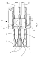
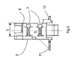
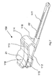
- the connecting element 1 comprises a housing 2, extending in the longitudinal direction of the same two receiving chambers 3, the are arranged one above the other according to FIG.
- the housing 2 is forward through an end wall 4 closed, in the corresponding to the receiving chambers 3, an opening 7 is provided in each case.
- Parallel to the receiving chambers 3 extend in the side surface 6 in the longitudinal direction slots 8, which extend into the end face 5 and thus also communicate with the openings 7. It revealed Thus, two opening areas, which extend in the transverse direction from the side surface 6 extend through the end wall 4 over a length L.
- each contact element 9 In the reception rooms 3 is in each case a contact element 9, each with a Cable 10 is connected, which from the end face 5 remote end of the housing 2 exit.
- the two cables 10 are used for power supply, for example Lamp of a headlight.
- the connecting element 1 serves to electrically conductive connection between the contact elements 9 to flat contact tongues to produce the lamp base of a lamp. This will be in connection later described in more detail with FIG.
- connection element 101 which has a housing portion, which corresponds substantially the housing 2 according to Figures 1 to 3 is formed, but wherein End wall with the end face 105 is shown by a separate cover 104.
- the for receiving the mating connector G forms a receiving chamber 24, in which the with the contact elements 109 connected terminal contact portions 117 in shape protrude from flat pins.
- the structure of the contact elements 109 receiving Housing section corresponds to the embodiment of Figures 1 to 3, to which reference is made to the description according to Figures 1 to 3.
- reference numerals are used for comparable elements in the figures 1 to 3 are provided with reference numerals, which increases by the numerical value 100 are.
- the views according to FIGS. 2 and 3 apply with regard to the contact elements 109 receiving housing portion and the housing 102nd
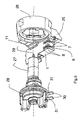
- FIG. 5 shows an assignment of the connecting element 1 according to Figures 1 to 3 a socket 26, a holder 25 is formed.
- a lamp 27 are introduced along the axis 29.
- the lamp 27 is with a pedestal 28 provided, protrude from the radially with respect to the axis 29 flat contact tongues 30.
- the flat contact tongues 30 are arranged offset along the axis 29, wherein their broad sides 31 form parallel planes on which the axis 29 perpendicular stands.
- the lamp 27 can with its lamp base 28 in an opening of the socket 26 are introduced and for mechanical fixing to this about the axis 29th be pivoted, with the flat contact tongues 30 through the opening 7 also move into the slot 8 and with the contact elements 9 in the housing 2 in Contact us.
- the length L the slot-shaped opening 7 along the end face 5, starting from the side surface 6 sized according to the entrance length of the flat contact tongues 30.
- the connecting element 1 is attached to the holder 25 by means of the fastening lugs 11 established.
- the first variant usually also used when first assembling a motor vehicle is, is the lamp 27 with its base 28 already mounted on the socket 26.
- the electrical connection is after mounting, for example, the Headlight made on the bodywork of the motor vehicle by the Connecting element 1, which is connected to the cables 10, on the holder 25 radially or is attached tangentially, wherein the lamp cap 28 of the lamp 27 in the mounted position to the socket 26 remains.
- connecting element 101 In the same way as described in connection with FIG Connection are produced in the connecting element 101 according to Figure 4, wherein for already provided with mating connectors cable with the embodiment of the invention a connecting element can be connected.
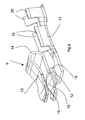
- a contact element 9 can be seen, the first contact arm 12 and a second contact arm 13 extending from a connected end 14 and at their free ends a first contact portion 15 and second contact portion 16 form, wherein the contact portions 15, 16 of the two contact arms 12 and 13 face each other and are intended to each have a flat contact tongue 30 to take in accordance with Figure 5 between them and to contact electrically.
- an intermediate piece 18 is connected bent, to a terminal contact portion 17 in the form of a crimp connection terminal (Crimp) is connected, which serves an electrical make conductive connection with the conductor of the cable 10, including a pair forming and opposing Leitercrimplaschen 19 are provided, the be crimped with the conductor of the cable 10.
- the two contact portions 15, 16 strive apart. same for in a direction transverse to it, so that an approximately centrally arranged, concentrated Contact area results.
- the diverging areas form feed funnels, the connecting or pivoting of the flat contact tongues between to facilitate the first contact arm 12 and the second contact arm 13 so that these are moved apart with progressive pivoting and on the Broad sides 31 of the flat contact tongues 30 according to Figure 5 can slide on.
- FIGS. 7 and 8 show a second embodiment of contact elements 109, which are intended for use in connection elements 101 according to FIG. there are the first contact arm 112 and the second contact arm 113 as well as in the Embodiment according to Figure 6 connected at one end 114 and each form a first contact portion 115 and second contact portion 116.
- integrally connected adapter 118 closes a terminal contact portion 117 in the form of a flat pin, whose broad sides 22 parallel to the broad side 21, for example of the second contact arm 113, is aligned.
- the design of the contact arms 112, 113 corresponds to the the first embodiment according to Figure 6, including the description of Figure 6 is referenced, with parts corresponding to those of Figure 6, with reference numerals are provided, which are increased to those of Figure 6 by the numerical value 100.
- FIG. 7 leaves a mutual one as shown in FIG Assignment of two contact elements 109 to, in which the terminal contact sections 117 are arranged side by side in the form of flat pin pins.
Applications Claiming Priority (2)
| Application Number | Priority Date | Filing Date | Title |
|---|---|---|---|
| DE102004004203A DE102004004203B4 (de) | 2004-01-27 | 2004-01-27 | Verbindungsanordnung mit einem Verbindungselement und einem Lampensockel |
| DE102004004203 | 2004-01-27 |
Publications (2)
| Publication Number | Publication Date |
|---|---|
| EP1560303A2 true EP1560303A2 (fr) | 2005-08-03 |
| EP1560303A3 EP1560303A3 (fr) | 2008-06-04 |
Family
ID=34638774
Family Applications (1)
| Application Number | Title | Priority Date | Filing Date |
|---|---|---|---|
| EP05000673A Withdrawn EP1560303A3 (fr) | 2004-01-27 | 2005-01-14 | Elément de contact pour la connexion électrique des feux principaux d' éclairage à un socle |
Country Status (4)
| Country | Link |
|---|---|
| US (1) | US7326072B2 (fr) |
| EP (1) | EP1560303A3 (fr) |
| JP (1) | JP4146841B2 (fr) |
| DE (1) | DE102004004203B4 (fr) |
Cited By (2)
| Publication number | Priority date | Publication date | Assignee | Title |
|---|---|---|---|---|
| WO2008107435A1 (fr) * | 2007-03-08 | 2008-09-12 | Osram Gesellschaft mit beschränkter Haftung | Phare |
| EP3431865B1 (fr) * | 2017-07-21 | 2022-09-07 | Gureak Lanean S.A. | Dispositif d'éclairage pour véhicule |
Families Citing this family (4)
| Publication number | Priority date | Publication date | Assignee | Title |
|---|---|---|---|---|
| ATE450754T1 (de) * | 2004-08-05 | 2009-12-15 | Koninkl Philips Electronics Nv | Lampe mit verbesserter schwingungsdämpfung |
| DE102004045369A1 (de) * | 2004-09-18 | 2006-03-23 | Hella Kgaa Hueck & Co. | Beleuchtungseinrichtung für Fahrzeuge |
| US20090242711A1 (en) * | 2008-03-25 | 2009-10-01 | Fang Lin Yang | Wire attachment device for vehicle |
| JP6448505B2 (ja) * | 2015-10-02 | 2019-01-09 | モレックス エルエルシー | カードエッジコネクタ |
Citations (3)
| Publication number | Priority date | Publication date | Assignee | Title |
|---|---|---|---|---|
| GB2204749A (en) * | 1986-12-02 | 1988-11-16 | Donald Taylor | Electrical couplings |
| DE29823160U1 (de) * | 1998-12-29 | 1999-02-25 | Schnippering Hugo Gmbh Co Kg | Lampenfassung aus Isolierstoff für H 7-Lampen |
| US20030045151A1 (en) * | 2001-08-31 | 2003-03-06 | Daniel Josquin | Arrangement for the electrical connection of a lamp |
Family Cites Families (14)
| Publication number | Priority date | Publication date | Assignee | Title |
|---|---|---|---|---|
| US4764854A (en) * | 1985-11-01 | 1988-08-16 | Koito Seisakusho Co., Ltd. | Mounting device for replaceable lamp assembly on reflector enclosure |
| US5174785A (en) * | 1990-07-17 | 1992-12-29 | Yazaki Corporation | Low insertion-withdrawal force electric connector |
| JP3337096B2 (ja) * | 1994-02-17 | 2002-10-21 | 住友電装株式会社 | バルブソケット |
| JP3493907B2 (ja) * | 1996-07-04 | 2004-02-03 | 住友電装株式会社 | バルブソケット |
| US6270235B1 (en) * | 1999-05-14 | 2001-08-07 | Osram Sylvania Inc. | Lamp and lamp based assembly |
| US6536929B1 (en) * | 2000-08-23 | 2003-03-25 | Forgacs Laszlo | Incandescent lamp for use in a reflector |
| JP3672817B2 (ja) * | 2000-12-25 | 2005-07-20 | 矢崎総業株式会社 | 補器のコネクタ装着構造 |
| US6467942B2 (en) * | 2001-01-12 | 2002-10-22 | Alcoa Fujikura Limited | Automotive lamp socket |
| US7014510B2 (en) * | 2001-10-04 | 2006-03-21 | Guide Corporation | Wedge base sealed lamp socket |
| FI115207B (fi) * | 2001-10-10 | 2005-03-31 | B Herrmans Ab Oy | Polttimon pidike |
| DE10200831A1 (de) * | 2002-01-02 | 2003-07-17 | Philips Intellectual Property | Lampe und Scheinwerfer zur einfachen Montage |
| JP4010449B2 (ja) * | 2002-08-19 | 2007-11-21 | 株式会社小糸製作所 | 車両用灯具のバルブ挿着構造 |
| DE10241585B4 (de) * | 2002-09-05 | 2005-07-28 | Eads Deutschland Gmbh | Lastengleitfallschirm-System |
| DE102004007150A1 (de) * | 2004-02-12 | 2005-08-25 | Patent-Treuhand-Gesellschaft für elektrische Glühlampen mbH | Sockel für eine Scheinwerferlampe und Scheinwerferlampe |
-
2004
- 2004-01-27 DE DE102004004203A patent/DE102004004203B4/de not_active Expired - Fee Related
- 2004-12-02 US US11/001,291 patent/US7326072B2/en not_active Expired - Fee Related
-
2005
- 2005-01-14 EP EP05000673A patent/EP1560303A3/fr not_active Withdrawn
- 2005-01-20 JP JP2005012828A patent/JP4146841B2/ja not_active Expired - Fee Related
Patent Citations (3)
| Publication number | Priority date | Publication date | Assignee | Title |
|---|---|---|---|---|
| GB2204749A (en) * | 1986-12-02 | 1988-11-16 | Donald Taylor | Electrical couplings |
| DE29823160U1 (de) * | 1998-12-29 | 1999-02-25 | Schnippering Hugo Gmbh Co Kg | Lampenfassung aus Isolierstoff für H 7-Lampen |
| US20030045151A1 (en) * | 2001-08-31 | 2003-03-06 | Daniel Josquin | Arrangement for the electrical connection of a lamp |
Cited By (2)
| Publication number | Priority date | Publication date | Assignee | Title |
|---|---|---|---|---|
| WO2008107435A1 (fr) * | 2007-03-08 | 2008-09-12 | Osram Gesellschaft mit beschränkter Haftung | Phare |
| EP3431865B1 (fr) * | 2017-07-21 | 2022-09-07 | Gureak Lanean S.A. | Dispositif d'éclairage pour véhicule |
Also Published As
| Publication number | Publication date |
|---|---|
| EP1560303A3 (fr) | 2008-06-04 |
| US20050164556A1 (en) | 2005-07-28 |
| DE102004004203B4 (de) | 2008-11-27 |
| DE102004004203A1 (de) | 2005-08-25 |
| JP2005216851A (ja) | 2005-08-11 |
| JP4146841B2 (ja) | 2008-09-10 |
| US7326072B2 (en) | 2008-02-05 |
Similar Documents
| Publication | Publication Date | Title |
|---|---|---|
| DE602004011002T2 (de) | Wasserdichter Verbinder und Zusammenbauverfahren | |
| DE112015002005B4 (de) | Rechtwinklige Verbinderanordnung | |
| DE102017113875B3 (de) | Elektrischer Stecker mit einem Schutzleiterkontakt und damit einstückig ausgebildeten Schutzleiterverbindungselement zur Erdung von Außenteilen | |
| DE112016002791B4 (de) | Gemeinschaftsverbinder | |
| DE10215956B4 (de) | Sonnenblendenarmverbindungsanordnung | |
| DE19857087C2 (de) | Elektrischer Verbinder für Kraftfahrzeugleuchte | |
| EP1560303A2 (fr) | Elément de contact pour la connexion électrique des feux principaux d' éclairage à un socle | |
| DE102019106980B3 (de) | Kontaktträger und Steckverbinder für eine geschirmte hybride Kontaktanordnung | |
| DE102004041809B4 (de) | Winkelkuppler | |
| EP1158610A2 (fr) | Connecteur enfichable de câble | |
| DE112013000709T5 (de) | Lampenfassung und Beleuchtungssystem | |
| EP2515388A1 (fr) | Dispositif de chauffage électrique | |
| EP3633802A1 (fr) | Prise de courant d'appareil, connecteur d'appareil et système de connecteur d'appareil | |
| EP1460734A2 (fr) | Adaptateur à un rail conducteur | |
| EP1128198B1 (fr) | Connecteur hybrid optique et électrique | |
| DE102005021375B4 (de) | Steckverbinder, insbesondere für Airbag-Zündsysteme | |
| EP1698026B1 (fr) | Fiche | |
| DE10323616A1 (de) | Schnellanschließbare Steckverbindung in Spannzangentechnik | |
| EP1206008B1 (fr) | Connecteur pour connecter des lignes électriques à un appareil électrique, en particulier pour un moteur | |
| EP1632009B1 (fr) | Element de contact et chambre de conduction complementaire pour un connecteur male ou femelle utilise en technique de raccordement autodenudant | |
| EP3412965B1 (fr) | Lampe intégrée | |
| DE19525801C2 (de) | Vorrichtung zum elektrisch leitenden Verbinden von zwei elektrischen Leitungen | |
| EP1811613A1 (fr) | Connecteur, de préférence Fakra Standard connecteur à angle droi droit, pour des applications véhicules | |
| DE102019120150A1 (de) | Leiteranschlussklemme | |
| DE2637967B2 (de) | Anschlußklemme fur eine Lampenschraubfassung |
Legal Events
| Date | Code | Title | Description |
|---|---|---|---|
| PUAI | Public reference made under article 153(3) epc to a published international application that has entered the european phase |
Free format text: ORIGINAL CODE: 0009012 |
|
| AK | Designated contracting states |
Kind code of ref document: A2 Designated state(s): AT BE BG CH CY CZ DE DK EE ES FI FR GB GR HU IE IS IT LI LT LU MC NL PL PT RO SE SI SK TR |
|
| AX | Request for extension of the european patent |
Extension state: AL BA HR LV MK YU |
|
| PUAL | Search report despatched |
Free format text: ORIGINAL CODE: 0009013 |
|
| AK | Designated contracting states |
Kind code of ref document: A3 Designated state(s): AT BE BG CH CY CZ DE DK EE ES FI FR GB GR HU IE IS IT LI LT LU MC NL PL PT RO SE SI SK TR |
|
| AX | Request for extension of the european patent |
Extension state: AL BA HR LV MK YU |
|
| AKX | Designation fees paid | ||
| STAA | Information on the status of an ep patent application or granted ep patent |
Free format text: STATUS: THE APPLICATION IS DEEMED TO BE WITHDRAWN |
|
| 18D | Application deemed to be withdrawn |
Effective date: 20081205 |
|
| REG | Reference to a national code |
Ref country code: DE Ref legal event code: 8566 |