EP1560303A2 - Contact element for electrical connecting of a head light to a lamp socket - Google Patents
Contact element for electrical connecting of a head light to a lamp socket Download PDFInfo
- Publication number
- EP1560303A2 EP1560303A2 EP05000673A EP05000673A EP1560303A2 EP 1560303 A2 EP1560303 A2 EP 1560303A2 EP 05000673 A EP05000673 A EP 05000673A EP 05000673 A EP05000673 A EP 05000673A EP 1560303 A2 EP1560303 A2 EP 1560303A2
- Authority
- EP
- European Patent Office
- Prior art keywords
- contact
- connecting element
- element according
- face
- flat
- Prior art date
- Legal status (The legal status is an assumption and is not a legal conclusion. Google has not performed a legal analysis and makes no representation as to the accuracy of the status listed.)
- Withdrawn
Links
Images


Classifications
-
- H—ELECTRICITY
- H01—ELECTRIC ELEMENTS
- H01R—ELECTRICALLY-CONDUCTIVE CONNECTIONS; STRUCTURAL ASSOCIATIONS OF A PLURALITY OF MUTUALLY-INSULATED ELECTRICAL CONNECTING ELEMENTS; COUPLING DEVICES; CURRENT COLLECTORS
- H01R13/00—Details of coupling devices of the kinds covered by groups H01R12/70 or H01R24/00 - H01R33/00
- H01R13/02—Contact members
- H01R13/10—Sockets for co-operation with pins or blades
- H01R13/11—Resilient sockets
- H01R13/113—Resilient sockets co-operating with pins or blades having a rectangular transverse section
-
- H—ELECTRICITY
- H01—ELECTRIC ELEMENTS
- H01R—ELECTRICALLY-CONDUCTIVE CONNECTIONS; STRUCTURAL ASSOCIATIONS OF A PLURALITY OF MUTUALLY-INSULATED ELECTRICAL CONNECTING ELEMENTS; COUPLING DEVICES; CURRENT COLLECTORS
- H01R33/00—Coupling devices specially adapted for supporting apparatus and having one part acting as a holder providing support and electrical connection via a counterpart which is structurally associated with the apparatus, e.g. lamp holders; Separate parts thereof
- H01R33/05—Two-pole devices
- H01R33/06—Two-pole devices with two current-carrying pins, blades or analogous contacts, having their axes parallel to each other
-
- F—MECHANICAL ENGINEERING; LIGHTING; HEATING; WEAPONS; BLASTING
- F21—LIGHTING
- F21S—NON-PORTABLE LIGHTING DEVICES; SYSTEMS THEREOF; VEHICLE LIGHTING DEVICES SPECIALLY ADAPTED FOR VEHICLE EXTERIORS
- F21S41/00—Illuminating devices specially adapted for vehicle exteriors, e.g. headlamps
- F21S41/10—Illuminating devices specially adapted for vehicle exteriors, e.g. headlamps characterised by the light source
- F21S41/19—Attachment of light sources or lamp holders
- F21S41/192—Details of lamp holders, terminals or connectors
-
- H—ELECTRICITY
- H01—ELECTRIC ELEMENTS
- H01R—ELECTRICALLY-CONDUCTIVE CONNECTIONS; STRUCTURAL ASSOCIATIONS OF A PLURALITY OF MUTUALLY-INSULATED ELECTRICAL CONNECTING ELEMENTS; COUPLING DEVICES; CURRENT COLLECTORS
- H01R2201/00—Connectors or connections adapted for particular applications
- H01R2201/26—Connectors or connections adapted for particular applications for vehicles
-
- Y—GENERAL TAGGING OF NEW TECHNOLOGICAL DEVELOPMENTS; GENERAL TAGGING OF CROSS-SECTIONAL TECHNOLOGIES SPANNING OVER SEVERAL SECTIONS OF THE IPC; TECHNICAL SUBJECTS COVERED BY FORMER USPC CROSS-REFERENCE ART COLLECTIONS [XRACs] AND DIGESTS
- Y10—TECHNICAL SUBJECTS COVERED BY FORMER USPC
- Y10S—TECHNICAL SUBJECTS COVERED BY FORMER USPC CROSS-REFERENCE ART COLLECTIONS [XRACs] AND DIGESTS
- Y10S439/00—Electrical connectors
- Y10S439/918—Multilamp vehicle panel
Abstract
Description
Die Erfindung betrifft ein Verbindungselement zum elektrisch leitenden Verbinden mit Flachkontaktzungen an einem Lampensockel einer Lampe, die durch eine Schwenkbewegung um eine Achse mit der Fassung einer Leuchte, insbesondere der eines Hauptscheinwerfers eines Kraftfahrzeuges, verbindbar ist.The invention relates to a connecting element for electrically conductive connection with Flat contact tongues on a lamp base of a lamp, by a pivoting movement about an axis with the socket of a lamp, in particular the one Headlight of a motor vehicle, is connectable.
Bei einem Kraftfahrzeug sind viele Arten von Lampen in Anwendung, die sich auch durch die Form ihres Lampensockels und die Anordnung und Ausbildung der Kontakte unterscheiden (sh. z.B. das Buch "Autoelektrik, Autoelektronik/Bosch", dritte aktualisierte Auflage 1998, Verlag Vieweg, Seiten 222 bis 227, sowie 234 und 235).In a motor vehicle many types of lamps are in use, too by the shape of its lamp cap and the arrangement and formation of the contacts (see, for example, the book "Autoelektrik, Autoelektronik / Bosch", third updated Edition 1998, Verlag Vieweg, pages 222 to 227, as well as 234 and 235).
Die US 2003/0045151A1 beschreibt eine Verbindungsanordnung für eine Leuchte mit einem Reflektor und mit einer an diesem über einen Bajonettverschluss festlegbaren Lampe, die entlang einer ersten Achse in eine Öffnung des Reflektors einführbar und mit diesem verbindbar ist. Die Lampe ist mit Flachkontaktstiften versehen, welche in einer gemeinsamen Ebene angeordnet sind, auf der die Achse, um den die Lampe schwenkbar ist, rechtwinklig steht. Nachdem die Lampe mit dem Reflektor durch eine Schwenkbewegung um die erste Achse fest verbunden ist, können die entsprechenden Gegenkontakte zu den Flachkontaktstiften durch eine Verlagerung eines Elementes bewirkt werden, welches die entsprechenden Gegenkontakte aufnimmt. Dabei kann das elektrische Verbinden dadurch geschehen, dass die Gegenkontaktelemente dadurch in Kontakt zu den Flachkontaktstiften gebracht werden, dass das sie aufnehmende Element um eine die erste Achse mit Abstand rechtwinklig kreuzende zweite Achse verschwenkt wird oder dieses entlang einer Achse, die parallel zur Achse der Flachkontaktstifte verläuft auf diese zu in Kontakt verschoben wird oder dieses um die Achse, um die feststehende Lampe verschwenkt wird, verschwenkt wird.US 2003/0045151 A1 describes a connection arrangement for a luminaire with a reflector and with a fixable on this via a bayonet lock Lamp insertable along a first axis in an opening of the reflector and is connectable with this. The lamp is equipped with flat contact pins, which are arranged in a common plane, on which the axis to which the Lamp is pivotable, standing at right angles. After the lamp with the reflector is firmly connected by a pivoting movement about the first axis, the corresponding mating contacts to the flat contact pins by a shift be effected of an element which receives the corresponding mating contacts. In this case, the electrical connection can be done by the mating contact elements thereby being brought into contact with the flat contact pins, that the receiving element about a first axis by a distance at right angles pivoting second axis is pivoted or this along an axis, the parallel to the axis of the flat contact pins extends to this moved into contact or this is pivoted about the axis to the fixed lamp is pivoted becomes.
Der Nachteil dabei ist, dass zunächst immer die Lampe mit dem Reflektor fest verbunden sein muss, ehe ein elektrischer Kontakt durch Bewegung des die entsprechenden Gegenkontakte aufnehmenden Elementes erzeugt werden kann. Nur dieses zweistufige Verbinden ist möglich, da zunächst die mechanische Verbindung zwischen der Lampe und dem Reflektor und danach die elektrische Verbindung hergestellt werden muss.The disadvantage of this is that initially always the lamp firmly connected to the reflector must be before an electrical contact by movement of the corresponding Mating contacts receiving element can be generated. Only this two-stage connection is possible because first the mechanical connection between the lamp and the reflector and then the electrical connection must be made.
Aufgabe der Erfindung ist es, ein Verbindungselement zum elektrisch leitenden Verbinden mit den Flachkontaktzungen eines Lampensockels zu schaffen, welche radial von dem Lampensockel vortreten, wobei dieser durch eine Schwenkbewegung an einer Fassung festlegbar ist, welcher wahlweise die Erzielung einer elektrisch leitenden Verbindung gleichzeitig mit der Schwenkbewegung des Lampensockels oder unabhängig davon durch Aufstecken des Verbindungselementes, das die mit den Flachkontaktzungen in Kontakt tretenden Kontaktelemente enthält, ermöglicht.The object of the invention is to provide a connecting element for electrically conductive connection to provide with the flat contact tongues of a lamp cap, which radially protrude from the lamp base, this by a pivoting movement a socket can be fixed, which optionally the achievement of an electrically conductive Connection simultaneously with the pivoting movement of the lamp base or regardless of attaching the connecting element, which with the Flat contact tongues in contact passing elements contains enabled.
Gelöst wird diese Aufgabe erfindungsgemäß durch ein Verbindungselement zum elektrisch leitenden Verbinden mit mindestens zwei radial aus einem Lampensockel, der durch eine Schwenkbewegung um eine Achse mit der Fassung einer Leuchte, insbesondere eines Hauptscheinwerfers eines Kraftfahrzeuges verbindbar ist, austretenden und entlang der Achse versetzten Flachkontaktzungen, deren Breitseiten quer zur Achse verlaufen, umfassend
- mindestens zwei aus einem elektrisch leitenden Material bestehende Kontaktelemente,
die jeweils
- zwei Kontaktarme aufweisen, die an einem Ende miteinander einstückig verbunden und gabelartig geformt sind, so dass ihre unverbundenen Endabschnitte einander gegenüberstehen und Kontaktabschnitte bilden, die dazu dienen, eine Flachkontaktzunge beidseitig an ihren Breitseiten zu kontaktieren,
- einen Anschlusskontaktabschnitt aufweisen, der mit einem Kontaktarm einstückig verbunden ist und von den Kontaktabschnitten weg vom verbundenen Ende vorsteht,
- ein Gehäuse, das
- eine vordere Stirnfläche und eine winklig dazu angeordnete Seitenfläche aufweist,
- je Kontaktelement eine Aufnahmekammer aufweist, welche eine Öffnung zur Stirnfläche und einen Schlitz aufweist, der von der Seitenfläche bis in die Aufnahmekammer und durch eine die Stirnfläche bildende Stirnwand bis in die Öffnung verläuft, wobei die Aufnahmekammern entsprechend der versetzten Anordnung der Flachkontaktzungen entlang der Achse übereinander angeordnet sind.
- at least two of an electrically conductive material contact elements, each
- two contact arms integrally connected and fork-shaped at one end so that their unconnected end portions face each other and form contact portions which serve to contact a flat contact tongue on both sides of their broad sides,
- a terminal contact portion integrally connected to a contact arm and projecting from the contact portions away from the connected end,
- a case that
- has a front end face and a side face arranged at an angle thereto,
- each contact element has a receiving chamber which has an opening to the end face and a slot which extends from the side surface into the receiving chamber and through an end wall forming the end face into the opening, wherein the receiving chambers according to the staggered arrangement of the flat contact tongues along the axis one above the other are arranged.
Von Vorteil bei dieser Ausbildung gegenüber einer bekannten Ausführungsform für Lampen, die durch eine Schwenkbewegung ihres Lampensockels um eine Achse mit der Fassung einer Leuchte verbunden werden und bei denen zur elektrisch leitenden Verbindung mit einem Verbindungselement Flachkontaktzungen parallel zur Achse vom Lampensockel vortreten, ist, dass mit der Schwenkbewegung des Lampensockels gleichzeitig zu der mechanischen Verbindung desselben mit der Fassung eine elektrisch leitende Verbindung der Flachkontaktzungen zu den Kontaktelementen des Verbindungselementes hergestellt wird. Eine solche Montageart wird vorwiegend bei dem Austausch einer montierten Leuchte gewählt. Bei der Herstellung eines Kraftfahrzeuges werden Lampen häufig bereits vormontiert an der Fassung angeliefert, um die Lampe geschützt zu transportieren und deren Funktion vor dem Zusammenbau überprüfen zu können. Bei der Montage des Kraftfahrzeuges wird beispielsweise dann der Hauptscheinwerfer zunächst mit der in der Lampenfassung befindlichen Lampe an der Karosserie montiert. Bei der erfindungsgemäßen Lösung wird dann ein radiales bzw. tangentiales Verbinden des Verbindungselementes mit den Flachkontaktzungen am Lampensockel möglich.An advantage of this embodiment over a known embodiment of Lamps, by a pivoting movement of their lamp cap around an axis with the socket of a lamp are connected and in which the electrically conductive Connection with a connection element Flat contact tongues parallel to the axis protruding from the lamp base is that with the pivotal movement of the lamp cap simultaneously with the mechanical connection of the same with the socket electrically conductive connection of the flat contact tongues to the contact elements of the connecting element is produced. Such a type of mounting becomes predominantly selected when replacing a mounted luminaire. In the production of a Motor vehicle lamps are often delivered pre-assembled to the socket, to transport the lamp protected and its function before assembly to be able to check. When mounting the motor vehicle, for example then the headlight first with the located in the lamp socket Lamp mounted on the body. In the solution according to the invention is then a radial or tangential connection of the connecting element with the Flat contact tongues on the lamp base possible.
In Ausgestaltung der Erfindung ist vorgesehen, dass die Öffnung ausgehend von der Seitenfläche entsprechend der Eintrittslänge der Flachkontaktzunge in die Aufnahmekammer bemessen ist.In an embodiment of the invention, it is provided that the opening, starting from the Side surface corresponding to the entry length of the flat contact tongue in the receiving chamber is measured.
Die erfindungsgemäße Lösung lässt verschiedene Varianten zu. So ist es möglich, den Anschlusskontaktabschnitt zur Quetschverbindung mit einem elektrischen Leiter eines Kabels auszubilden. Hierzu kann beispielsweise ein Crimpabschnitt mit Crimplaschen vorgesehen sein. Dies bedeutet, dass ein Kabel unmittelbar mit dem Anschlusskontaktabschnitt und damit auch mit den Kontaktelementen verbunden wird, die dann im Gehäuse aufgenommen werden.The solution according to the invention allows for different variants. So it is possible the terminal contact portion for crimping with an electrical conductor to form a cable. For this purpose, for example, a crimping section with Crimplaschen be provided. This means that a cable directly to the terminal contact section and thus also connected to the contact elements, which are then housed in the housing.
Es ist jedoch auch möglich, den Anschlusskontaktabschnitt als Steckerstift auszubilden, so dass an diesen ein bereits an dem Kabel vorgesehener Stecker mit als Anschlussbuchsen gestalteten Kontaktelementen anschließbar ist. Vorzugsweise ist in diesem Falle der Steckerstift als Flachsteckerstift gestaltet. Da in der Regel zwei Kontaktelemente vorgesehen sind, ist es günstig, wenn der Flachsteckerstift mit seinen Breitseiten quer zur Breitseite der Kontaktarme verläuft, so dass nur eine Sorte von Kontaktelementen mit Flachsteckerstiften für verschiedene Anordnungsvarianten hergestellt zu werden braucht.However, it is also possible to form the terminal contact portion as a plug pin, so that at this already provided on the cable connector with as sockets designed contact elements can be connected. Preferably, in designed in this case, the pin as a flat pin. As a rule, two Contact elements are provided, it is advantageous if the flat pin with his Broad sides transverse to the broad side of the contact arms, leaving only one sort of contact elements with flat plug pins for different arrangement variants needs to be made.
Für den Fall der Ausrüstung des Verbindungselementes mit Kontaktelementen, die mit Flachsteckerstiften versehen sind, ist vorgesehen, dass das Gehäuse einen Buchsenabschnitt aufweist, in den die Steckerstifte geschützt vorstehen.In the case of the equipment of the connecting element with contact elements, the are provided with flat pins, it is provided that the housing a Socket portion, in which protrude the pins protected.
Das Gehäuse kann mehrteilig ausgebildet sein, wobei die die Stirnfläche aufweisende Stirnwand durch einen Deckel gebildet ist. Hierdurch wird die Montage der Kontaktelemente im Gehäuse vereinfacht.The housing may be formed in several parts, wherein the end face having End wall is formed by a lid. As a result, the assembly of the contact elements simplified in the housing.
Um das Verbindungselement nahe zur Fassung festlegen zu können, ist das Gehäuse mit Haltemitteln zur Verbindung mit einem Halter versehen, welcher beispielsweise Bestandteil der Fassung sein kann.In order to set the connection element close to the socket, the housing is provided with holding means for connection to a holder, which for example Part of the version can be.
Um das Einführen der Flachkontaktzungen in die Kontaktelemente zu erleichtern ist vorgesehen, dass die Kontaktabschnitte der Kontaktarme seitlich zum Schlitz hin und zur Öffnung hin ausgehend von ihren mit den Flachkontaktzungen in Kontakt tretenden Bereichen auseinander streben.In order to facilitate the insertion of the flat contact tongues in the contact elements provided that the contact portions of the contact arms laterally to the slot and towards the opening, starting from their contact with the flat contact blades Striving for areas apart.
Vorzugsweise ist jedoch vorgesehen, dass die Kontaktabschnitte der Kontaktarme ausgehend von ihren mit den in Kontakt tretenden Bereichen sowohl seitlich zum Schlitz hin als auch von diesem weg auseinander streben.Preferably, however, it is provided that the contact portions of the contact arms starting from their contact with the areas both side to Slit out as well as stride away from this.
Bevorzugte Ausführungsbeispiele der Erfindung sind in der Zeichnung schematisch dargestellt.Preferred embodiments of the invention are schematic in the drawing shown.
Es zeigt
Figur 1- einen Längsschnitt durch ein erfindungsgemäßes Verbindungselement,
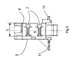
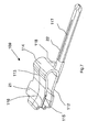
Figur 2- eine Seitenansicht des Verbindungselementes,
Figur 3- eine Ansicht auf die Stirnfläche des Verbindungselementes in Pfeilrichtung
X von
Figur 2, Figur 4- einen Längsschnitt durch eine zweite Ausführungsform eines Verbindungselementes gemäß der Erfindung,
Figur 5- eine perspektivische Darstellung der Zuordnung eines Verbindungselementes
gemäß
Figuren 1 bis 3 zu einer Lampenfassung und einer diese aufnehmenden Lampe, Figur 6- eine perspektivische Darstellung eines Kontaktelementes in einer ersten
Ausführungsform gemäß der Erfindung passend zu dem Verbindungselement
gemäß
Figuren 1 bis 3, Figur 7- die gegenseitige Zuordnung zweier Verbindungselemente in einer
Ausführungsform, die zu dem Verbindungselement gemäß
Figur 4 passt, Figur 8- die gegenseitige Zuordnung zweier Kontaktelemente gemäß
Figur 7 in einer gegenüber derFigur 7 abgewandelten Blickrichtung.
- FIG. 1
- a longitudinal section through a connecting element according to the invention,
- FIG. 2
- a side view of the connecting element,
- FIG. 3
- a view of the end face of the connecting element in the direction of arrow X of Figure 2,
- FIG. 4
- a longitudinal section through a second embodiment of a connecting element according to the invention,
- FIG. 5
- a perspective view of the assignment of a connecting element according to Figures 1 to 3 to a lamp holder and a lamp receiving this,
- FIG. 6
- 3 is a perspective view of a contact element in a first embodiment according to the invention, suitable for the connecting element according to FIGS. 1 to 3,
- FIG. 7
- the mutual association of two connecting elements in an embodiment that matches the connecting element according to FIG. 4,
- FIG. 8
- the mutual association of two contact elements according to Figure 7 in a comparison with the figure 7 modified viewing direction.
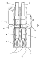
Zunächst wird eine erste Ausführungsform eines Verbindungselementes 1 anhand
der Figuren 1 bis 3 beschrieben. Das Verbindungselement 1 umfasst ein Gehäuse 2,
das in Längsrichtung desselben verlaufend zwei Aufnahmekammern 3 besitzt, die
gemäß Figur 1 übereinander angeordnet sind. Das Gehäuse 2 ist nach vorne durch
eine Stirnwand 4 verschlossen, in der korrespondierend zu den Aufnahmekammern
3 jeweils eine Öffnung 7 vorgesehen ist. Parallel zu den Aufnahmekammern 3
erstrecken sich in der Seitenfläche 6 in Längsrichtung Schlitze 8, die bis in die Stirnfläche
5 reichen und damit auch mit den Öffnungen 7 in Verbindung stehen. Es ergeben
sich somit zwei Öffnungsbereiche, die sich in Querrichtung ausgehend von
der Seitenfläche 6 durch die Stirnwand 4 über eine Länge L erstrecken. In den Aufnahmekammern
3 befindet sich jeweils ein Kontaktelement 9, das jeweils mit einem
Kabel 10 verbunden ist, der aus dem der Stirnfläche 5 entfernten Ende des Gehäuses
2 austritt. Die beiden Kabel 10 dienen zur Stromversorgung beispielsweise der
Lampe eines Hauptscheinwerfers. Das Verbindungselement 1 dient dazu, eine elektrisch
leitende Verbindung zwischen den Kontaktelementen 9 zu Flachkontaktzungen
am Lampensockel einer Lampe herzustellen. Dies wird nachfolgend noch in Verbindung
mit Figur 5 näher beschrieben.First, a first embodiment of a connecting
Zur Festlegung des Verbindungselementes 1 sind an diesem Befestigungsansätze
11 vorgesehen, die sich in Führungen eines Halters einschieben lassen, der Teil der
Fassung oder nahe derselben angebracht ist.To fix the connecting
Während bei der Ausführungsform gemäß Figuren 1 bis 3 die Kabel 10 unmittelbar
mit den Kontaktelementen 9 verbunden sind, sieht die Ausbildung des Verbindungselementes
101 gemäß Figur 4 eine Schnittstelle mit Anschlusskontaktabschnitten
117 in Form von Steckerstiften 117 vor, die mit jeweils einem Kontaktelement 109
verbunden sind. Die Anschlusskontaktabschnitte 118 sind mit einem Gegenstecker
G verbindbar. Bei dem Verbindungselement 101 gemäß Figur 4 ist ein Gehäuse 102
vorgesehen, das einen Gehäuseabschnitt aufweist, der im wesentlichen entsprechend
dem Gehäuse 2 gemäß Figuren 1 bis 3 ausgebildet ist, wobei jedoch die
Stirnwand mit der Stirnfläche 105 durch einen separaten Deckel 104 dargestellt ist.
An diesen Gehäuseabschnitt ist jedoch ein Buchsenabschnitt 23 angeschlossen, der
zur Aufnahme des Gegensteckers G eine Aufnahmekammer 24 bildet, in die die mit
den Kontaktelementen 109 verbundenen Anschlusskontaktabschnitte 117 in Form
von Flachsteckerstiften vorstehen. Der Aufbau des die Kontaktelemente 109 aufnehmenden
Gehäuseabschnitts entspricht der Ausführungsform gemäß Figuren 1
bis 3, wozu auf die Beschreibung gemäß Figuren 1 bis 3 verwiesen wird. In der Figur
4 sind jedoch Bezugszeichen verwendet, die für vergleichbare Elemente bei den Figuren
1 bis 3 mit Bezugszeichen versehen sind, die um den Zahlenwert 100 erhöht
sind. Die Ansichten gemäß Figuren 2 und 3 gelten hinsichtlich des die Kontaktelemente
109 aufnehmenden Gehäuseabschnittes auch für das Gehäuse 102.While in the embodiment according to Figures 1 to 3, the
Bezüglich der Beschreibung dieser Teile wird auf die der Figuren 1 bis 3 verwiesen.With regard to the description of these parts, reference is made to FIGS. 1 to 3.
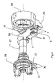
Figur 5 zeigt eine Zuordnung des Verbindungselementes 1 gemäß Figuren 1 bis 3 zu
einer Fassung 26, der ein Halter 25 angeformt ist. In die Fassung 26 kann eine Lampe
27 entlang der Achse 29 eingeführt werden. Die Lampe 27 ist mit einem Sockel
28 versehen, von dem radial bezüglich der Achse 29 Flachkontaktzungen 30 vorstehen.
Die Flachkontaktzungen 30 sind entlang der Achse 29 versetzt angeordnet, wobei
ihre Breitseiten 31 parallele Ebenen bilden, auf denen die Achse 29 senkrecht
steht. Die Lampe 27 kann mit ihrem Lampensockel 28 in eine Öffnung der Fassung
26 eingeführt werden und zur mechanischen Festlegung an dieser um die Achse 29
verschwenkt werden, wobei sich die Flachkontaktzungen 30 über die Öffnung 7 auch
in den Schlitz 8 hinein bewegen und mit den Kontaktelementen 9 im Gehäuse 2 in
Kontakt treten. Um dies zu gewährleisten ist, wie aus Figur 3 ersichtlich, die Länge L
der schlitzförmigen Öffnung 7 entlang der Stirnfläche 5 ausgehend von der Seitenfläche
6 entsprechend der Eintrittslänge der Flachkontaktzungen 30 bemessen.Figure 5 shows an assignment of the connecting
Das Verbindungselement 1 ist an dem Halter 25 mittels der Befestigungsansätze 11
festgelegt. Es sind zwei Montagevarianten möglich. Bei der ersten Variante, die üblicherweise
auch beim erstmaligen Zusammenbau eines Kraftfahrzeuges eingesetzt
wird, befindet sich die Lampe 27 mit ihrem Sockel 28 bereits montiert an der Fassung
26. Die elektrische Verbindung wird nach der Montage beispielsweise des
Hauptscheinwerfers an der Karosserie des Kraftfahrzeuges hergestellt, indem das
Verbindungselement 1, das mit den Kabeln 10 verbunden ist, auf den Halter 25 radial
bzw. tangential aufgesteckt wird, wobei der Lampensockel 28 der Lampe 27 in der
montierten Position zur Fassung 26 verbleibt. Ist ein solches Kraftfahrzeug ausgerüstet
und in Benutzung und muss eine Lampe 27 ausgetauscht werden, kann diese
durch Verschwenken des Lampensockels 28 in der Fassung 26 um die Achse 29
sowohl von der Fassung 26 als auch hinsichtlich der elektrischen Verbindung der
Flachkontaktzungen 30 gelöst werden, da diese beim Verschwenken des Lampensockels
28 auch außer Eingriff zum Verbindungselement 1 und den darin befindlichen
Kontaktelementen 9 gelangen. Die Montage einer neuen Lampe erfolgt entsprechend
umgekehrt, d.h. der Lampensockel 28 einer neuen Lampe 27 wird in die
Lampenfassung 26 entlang der Achse 29 eingeführt und danach so verschwenkt,
dass die Flachkontaktzungen 30 in Eingriff zu den Öffnungen 7 bzw. den Schlitzen 8
gelangen und damit zu den nicht sichtbaren Kontaktelementen 9 in Kontakt treten
können, wodurch auch eine elektrische Verbindung hergestellt wird. Die Ausführungsform
ermöglicht also, dass sowohl gleichzeitig durch die Schwenkbewegung
des Lampensockels 28 eine mechanische Verbindung mit der Lampenfassung 26
und auch eine elektrische Verbindung mit den Kontaktelementen des Verbindungselementes
1 hergestellt werden.The connecting
In gleicher Weise wie im Zusammenhang mit Figur 5 beschrieben kann auch eine
Verbindung bei dem Verbindungselement 101 gemäß Figur 4 erzeugt werden, wobei
für bereits mit Gegensteckern versehene Kabel mit der erfindungsgemäßen Ausführungsform
eines Verbindungselementes verbunden werden können.In the same way as described in connection with FIG
Connection are produced in the connecting
Die bei den beiden unterschiedlichen Ausführungsformen gemäß Figuren 1 bis 3 einerseits
und Figur 4 andererseits verwendeten Kontaktelemente 9, 109 werden
nachfolgend unter Bezugnahme auf die Figuren 6 bis 8 näher beschrieben, wobei
Figur 6 eine perspektivische Darstellung eines Kontaktelementes 9 für die Ausführungsform
eines Verbindungselementes 1 gemäß Figuren 1 bis 3 bestimmt ist.The one with the two different embodiments according to figures 1 to 3
and Figure 4, on the other hand, used
Aus Figur 6 ist ein Kontaktelement 9 ersichtlich, das einen ersten Kontaktarm 12 und
einen zweiten Kontaktarm 13 umfasst, die von einem verbundenen Ende 14 ausgehen
und an ihren freien Enden einen ersten Kontaktabschnitt 15 bzw. zweiten Kontaktabschnitt
16 bilden, wobei die Kontaktabschnitte 15, 16 der beiden Kontaktarme
12 bzw. 13 einander gegenüberstehen und dazu bestimmt sind, jeweils eine Flachkontaktzunge
30 gemäß Figur 5 zwischen sich aufzunehmen und elektrisch zu kontaktieren.
Mit dem ersten Kontaktarm 12 ist ein Zwischenstück 18 abgebogen verbunden,
an das ein Anschlusskontaktabschnitt 17 in Form eines Quetschverbindungsanschlusses
(Crimpanschlusses) angeschlossen ist, der dazu dient, eine elektrisch
leitende Verbindung mit dem Leiter des Kabels 10 herzustellen, wozu ein Paar
bildende und sich gegenüberstehende Leitercrimplaschen 19 vorgesehen sind, die
mit dem Leiter des Kabels 10 quetschverbunden werden. Darüber hinaus sind zwei
gegenüberliegende Isolierungscrimplaschen 20 an dem Anschlusskontaktabschnitt
17, der U-förmig geformt ist, angeordnet. Diese nehmen zwischen sich die Isolierung
des Kabel 10 auf und werden an diese angepresst, um das Kabel 10 zu halten.From Figure 6, a
Zum freien Ende hin, d.h. von dem verbundenen Ende 14 der beiden Kontaktarme
12, 13 weg, streben die beiden Kontaktabschnitte 15, 16 auseinander. Gleiches gilt
in einer Richtung quer dazu, so dass sich ein etwa mittig angeordneter, konzentrierter
Kontaktbereich ergibt. Die auseinanderstrebenden Bereiche bilden Einführungstrichter,
die das Verbinden bzw. Einschwenken der Flachkontaktzungen zwischen
den ersten Kontaktarm 12 und den zweiten Kontaktarm 13 erleichtern sollen, so dass
diese bei fortschreitendem Einschwenken auseinander bewegt werden und auf die
Breitseiten 31 der Flachkontaktzungen 30 gemäß Figur 5 aufgleiten können.Toward the free end, i. from the
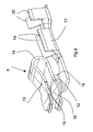
Die Figuren 7 und 8 zeigen eine zweite Ausführungsform von Kontaktelementen 109,
die zum Einsatz bei Verbindungselementen 101 gemäß Figur 4 bestimmt sind. Dabei
sind der erste Kontaktarm 112 und der zweite Kontaktarm 113 ebenso wie bei der
Ausführungsform gemäß Figur 6 an einem Ende 114 verbunden und bilden jeweils
einen ersten Kontaktabschnitt 115 bzw. zweiten Kontaktabschnitt 116. An das mit
dem ersten Kontaktarm 112 einstückig verbundene Zwischenstück 118 schließt sich
ein Anschlusskontaktabschnitt 117 in Form eines Flachsteckerstifts an, dessen Breitseiten
22 parallel zur Breitseite 21, beispielsweise des zweiten Kontaktarmes 113,
ausgerichtet ist. Ansonsten entspricht die Gestaltung der Kontaktarme 112, 113 der
der ersten Ausführungsform gemäß Figur 6, wozu auf die Beschreibung zur Figur 6
verwiesen wird, wobei Teile, die denen von Figur 6 entsprechen, mit Bezugszeichen
versehen sind, die zu denen gemäß Figur 6 um den Zahlenwert 100 erhöht sind.FIGS. 7 and 8 show a second embodiment of
Die Ausführungsform gemäß Figur 7 lässt, wie in Figur 8 gezeigt, eine gegenseitige
Zuordnung von zwei Kontaktelementen 109 zu, bei der die Anschlusskontaktabschnitte
117 in Form der Flachsteckerstifte nebeneinander angeordnet sind. The embodiment according to FIG. 7 leaves a mutual one as shown in FIG
Assignment of two
- 1, 1011, 101
- Verbindungselementconnecting element
- 2, 1022, 102
- Gehäusecasing
- 3, 1033, 103
- Aufnahmekammerreceiving chamber
- 4, 1044, 104
- Stirnwand / DeckelEnd wall / lid
- 5, 1055, 105
- Stirnflächeface
- 6, 1066, 106
- Seitenflächeside surface
- 7, 1077, 107
- Öffnungopening
- 8, 1088, 108
- Schlitzslot
- 9, 1099, 109
- Kontaktelementcontact element
- 1010
- Kabelelectric wire
- 11, 11111, 111
- Befestigungsansatz/HaltemittelFastening attachment / holding means
- 12, 11212, 112
- erster Kontaktarmfirst contact arm
- 13, 11313, 113
- zweiter Kontaktarmsecond contact arm
- 14, 11414, 114
- verbundenes Endeconnected end
- 15, 11515, 115
- erster Kontaktabschnittfirst contact section
- 16, 11616, 116
- zweiter Kontaktabschnittsecond contact section
- 17, 11717, 117
- AnschlusskontaktabschnittTerminal contact portion
- 18, 11818, 118
- Zwischenstückconnecting piece
- 1919
- LeitercrimplascheLeitercrimplasche
- 2020
- IsolierungscrimplascheIsolierungscrimplasche
- 2121
- Breitseite KontaktarmBroadside contact arm
- 2222
- Breitseite SteckerstiftBroadside connector pin
- 2323
- Buchsenabschnittbushing section
- 2424
- Aufnahmekammerreceiving chamber
- 2525
- Halterholder
- 2626
- Fassungversion
- 2727
- Lampe lamp
- 2828
- Lampensockellamp base
- 2929
- Achseaxis
- 3030
- FlachkontaktzungeFlat contact tongue
- 3131
- Breitseite der FlachkontaktzungeBroad side of the flat contact tongue
- GG
- GegensteckerMating connector
- LL
- Längelength
Claims (11)
dadurch gekennzeichnet, dass die Öffnung (7, 107) ausgehend von der Seitenfläche (6, 106) entsprechend der Eintrittslänge der Flachkontaktzunge (30) in die Aufnahmekammer (3, 103) bemessen ist.Connecting element according to claim 1,
characterized in that the opening (7, 107), starting from the side surface (6, 106) corresponding to the entry length of the flat contact tongue (30) in the receiving chamber (3, 103) is dimensioned.
dadurch gekennzeichnet, dass der Anschlusskontaktabschnitt (17) zur Quetschverbindung mit einem elektrischen Leiter eines Kabels (10) ausgebildet ist.Connecting element according to claim 1,
characterized in that the terminal contact portion (17) is formed for crimping with an electrical conductor of a cable (10).
dadurch gekennzeichnet, dass der Anschlusskontaktabschnitt (117) als Steckerstift ausgebildet ist.Connecting element according to claim 1,
characterized in that the terminal contact portion (117) is designed as a plug pin.
dadurch gekennzeichnet, dass der Steckerstift (117) ein Flachsteckerstift ist.Connecting element according to claim 4,
characterized in that the plug pin (117) is a tab pin.
dadurch gekennzeichnet, dass der Flachsteckerstift (117) mit seinen Breitseiten (22) quer zu der Breitseite (21) der Kontaktarme (112, 113) verläuftConnecting element according to claim 5,
characterized in that the flat pin (117) extends with its broad sides (22) transversely to the broad side (21) of the contact arms (112, 113)
dadurch gekennzeichnet, dass das Gehäuse (102) einen Buchsenabschnitt (23) aufweist, in den die Steckerstifte (117) vorstehenConnecting element according to claim 4,
characterized in that the housing (102) has a bushing portion (23) into which the plug pins (117) protrude
dadurch gekennzeichnet, dass das Gehäuse (102) mehrteilig ausgebildet ist und die die Stirnfläche (105) aufweisende Stirnwand (104) durch einen Deckel (104) gebildet istConnecting element according to claim 1,
characterized in that the housing (102) is formed in several parts and the end face (105) having end wall (104) by a cover (104) is formed
dadurch gekennzeichnet, dass das Gehäuse (2, 102) Haltemittel (11, 111) zur Verbindung mit einem Halter (25) aufweist.Connecting element according to claim 1,
characterized in that the housing (2, 102) holding means (11, 111) for connection to a holder (25).
dadurch gekennzeichnet, dass die Kontaktabschnitte (15, 115; 16, 116) der Kontaktarme (12, 112; 13, 113) seitlich zum Schlitz (8, 108) hin und zur Öffnung (7, 107) hin ausgehend von ihren mit den Flachkontaktzungen (30) in Kontakt tretenden Bereichen auseinander streben.Connecting element according to claim 1,
characterized in that the contact portions (15, 115, 16, 116) of the contact arms (12, 112, 13, 113) extend laterally toward the slot (8, 108) and towards the opening (7, 107), starting from their contact with the flat contact tongues (30) diverge in contacting areas.
dadurch gekennzeichnet, dass die Kontaktabschnitte (15, 115; 16, 116) der Kontaktarme (12, 112; 13, 113) ausgehend von ihren mit den in Kontakt tretenden Bereichen sowohl seitlich zum Schlitz (8, 108) hin als auch von diesem weg auseinander streben.Connecting element according to claim 9,
characterized in that the contact portions (15, 115, 16, 116) of the contact arms (12, 112, 13, 113) both from the side in contact with the contact areas both laterally to the slot (8, 108) and away diverge.
Applications Claiming Priority (2)
| Application Number | Priority Date | Filing Date | Title |
|---|---|---|---|
| DE102004004203A DE102004004203B4 (en) | 2004-01-27 | 2004-01-27 | Connecting arrangement with a connecting element and a lamp cap |
| DE102004004203 | 2004-01-27 |
Publications (2)
| Publication Number | Publication Date |
|---|---|
| EP1560303A2 true EP1560303A2 (en) | 2005-08-03 |
| EP1560303A3 EP1560303A3 (en) | 2008-06-04 |
Family
ID=34638774
Family Applications (1)
| Application Number | Title | Priority Date | Filing Date |
|---|---|---|---|
| EP05000673A Withdrawn EP1560303A3 (en) | 2004-01-27 | 2005-01-14 | Contact element for electrical connecting of a head light to a lamp socket |
Country Status (4)
| Country | Link |
|---|---|
| US (1) | US7326072B2 (en) |
| EP (1) | EP1560303A3 (en) |
| JP (1) | JP4146841B2 (en) |
| DE (1) | DE102004004203B4 (en) |
Cited By (2)
| Publication number | Priority date | Publication date | Assignee | Title |
|---|---|---|---|---|
| WO2008107435A1 (en) * | 2007-03-08 | 2008-09-12 | Osram Gesellschaft mit beschränkter Haftung | Headlight |
| EP3431865B1 (en) * | 2017-07-21 | 2022-09-07 | Gureak Lanean S.A. | Lighting device for a vehicle |
Families Citing this family (4)
| Publication number | Priority date | Publication date | Assignee | Title |
|---|---|---|---|---|
| US7658535B2 (en) * | 2004-08-05 | 2010-02-09 | Koninklijke Philips Electronics, N.V. | Lamp having improved vibration damping |
| DE102004045369A1 (en) * | 2004-09-18 | 2006-03-23 | Hella Kgaa Hueck & Co. | Lighting device for vehicles |
| US20090242711A1 (en) * | 2008-03-25 | 2009-10-01 | Fang Lin Yang | Wire attachment device for vehicle |
| JP6448505B2 (en) * | 2015-10-02 | 2019-01-09 | モレックス エルエルシー | Card edge connector |
Citations (3)
| Publication number | Priority date | Publication date | Assignee | Title |
|---|---|---|---|---|
| GB2204749A (en) * | 1986-12-02 | 1988-11-16 | Donald Taylor | Electrical couplings |
| DE29823160U1 (en) * | 1998-12-29 | 1999-02-25 | Schnippering Hugo Gmbh Co Kg | Lamp holder made of insulating material for H 7 lamps |
| US20030045151A1 (en) * | 2001-08-31 | 2003-03-06 | Daniel Josquin | Arrangement for the electrical connection of a lamp |
Family Cites Families (14)
| Publication number | Priority date | Publication date | Assignee | Title |
|---|---|---|---|---|
| US4764854A (en) * | 1985-11-01 | 1988-08-16 | Koito Seisakusho Co., Ltd. | Mounting device for replaceable lamp assembly on reflector enclosure |
| US5174785A (en) * | 1990-07-17 | 1992-12-29 | Yazaki Corporation | Low insertion-withdrawal force electric connector |
| JP3337096B2 (en) * | 1994-02-17 | 2002-10-21 | 住友電装株式会社 | Valve socket |
| JP3493907B2 (en) * | 1996-07-04 | 2004-02-03 | 住友電装株式会社 | Valve socket |
| US6270235B1 (en) * | 1999-05-14 | 2001-08-07 | Osram Sylvania Inc. | Lamp and lamp based assembly |
| US6536929B1 (en) * | 2000-08-23 | 2003-03-25 | Forgacs Laszlo | Incandescent lamp for use in a reflector |
| JP3672817B2 (en) * | 2000-12-25 | 2005-07-20 | 矢崎総業株式会社 | Auxiliary connector mounting structure |
| US6467942B2 (en) * | 2001-01-12 | 2002-10-22 | Alcoa Fujikura Limited | Automotive lamp socket |
| US7014510B2 (en) * | 2001-10-04 | 2006-03-21 | Guide Corporation | Wedge base sealed lamp socket |
| FI115207B (en) * | 2001-10-10 | 2005-03-31 | B Herrmans Ab Oy | Holder for light bulb |
| DE10200831A1 (en) * | 2002-01-02 | 2003-07-17 | Philips Intellectual Property | Lamp and headlights for easy installation |
| JP4010449B2 (en) * | 2002-08-19 | 2007-11-21 | 株式会社小糸製作所 | Bulb insertion structure for vehicular lamp |
| DE10241585B4 (en) * | 2002-09-05 | 2005-07-28 | Eads Deutschland Gmbh | Lastengleitfallschirm system |
| DE102004007150A1 (en) * | 2004-02-12 | 2005-08-25 | Patent-Treuhand-Gesellschaft für elektrische Glühlampen mbH | Base for a headlamp and headlamp |
-
2004
- 2004-01-27 DE DE102004004203A patent/DE102004004203B4/en not_active Expired - Fee Related
- 2004-12-02 US US11/001,291 patent/US7326072B2/en not_active Expired - Fee Related
-
2005
- 2005-01-14 EP EP05000673A patent/EP1560303A3/en not_active Withdrawn
- 2005-01-20 JP JP2005012828A patent/JP4146841B2/en not_active Expired - Fee Related
Patent Citations (3)
| Publication number | Priority date | Publication date | Assignee | Title |
|---|---|---|---|---|
| GB2204749A (en) * | 1986-12-02 | 1988-11-16 | Donald Taylor | Electrical couplings |
| DE29823160U1 (en) * | 1998-12-29 | 1999-02-25 | Schnippering Hugo Gmbh Co Kg | Lamp holder made of insulating material for H 7 lamps |
| US20030045151A1 (en) * | 2001-08-31 | 2003-03-06 | Daniel Josquin | Arrangement for the electrical connection of a lamp |
Cited By (2)
| Publication number | Priority date | Publication date | Assignee | Title |
|---|---|---|---|---|
| WO2008107435A1 (en) * | 2007-03-08 | 2008-09-12 | Osram Gesellschaft mit beschränkter Haftung | Headlight |
| EP3431865B1 (en) * | 2017-07-21 | 2022-09-07 | Gureak Lanean S.A. | Lighting device for a vehicle |
Also Published As
| Publication number | Publication date |
|---|---|
| EP1560303A3 (en) | 2008-06-04 |
| JP4146841B2 (en) | 2008-09-10 |
| DE102004004203A1 (en) | 2005-08-25 |
| JP2005216851A (en) | 2005-08-11 |
| DE102004004203B4 (en) | 2008-11-27 |
| US7326072B2 (en) | 2008-02-05 |
| US20050164556A1 (en) | 2005-07-28 |
Similar Documents
| Publication | Publication Date | Title |
|---|---|---|
| DE602004011002T2 (en) | Waterproof connector and assembly method | |
| DE112015002005B4 (en) | Right angle connector assembly | |
| DE102017113875B3 (en) | Electrical plug with a protective conductor contact and thus integrally formed protective conductor connection element for grounding of external parts | |
| DE112016002791B4 (en) | community connector | |
| DE10215956B4 (en) | Sonnenblendenarmverbindungsanordnung | |
| DE19857087C2 (en) | Electrical connector for automotive lamp | |
| EP1560303A2 (en) | Contact element for electrical connecting of a head light to a lamp socket | |
| DE102019106980B3 (en) | Contact carriers and connectors for a shielded hybrid contact arrangement | |
| DE102004041809B4 (en) | angle coupler | |
| EP1158610A2 (en) | Plug-in cable connector | |
| DE112013000709T5 (en) | Lamp socket and lighting system | |
| EP2515388A1 (en) | Electric heating device | |
| EP3633802A1 (en) | Device socket, device plug and socket connector system | |
| EP1460734A2 (en) | Conductor rail adapter | |
| EP1128198B1 (en) | Combined electrical and optical connector | |
| DE102005021375B4 (en) | Connectors, in particular for airbag ignition systems | |
| EP1698026B1 (en) | Plug | |
| DE10323616A1 (en) | Rapid connection plug or socket connector in clamping jaws technology has contact partner with region in form of clamping jaws for accommodating stripped end of line of especially multi-strand cable | |
| EP1206008B1 (en) | Connector to connect electrical lines to an electrical device, in particular for a motor | |
| EP1632009B1 (en) | Contact element and additional conduction chamber for a plug or socket produced according to insulating-piercing connecting technology | |
| EP3412965B1 (en) | Integrated lights | |
| DE19525801C2 (en) | Device for the electrically conductive connection of two electrical lines | |
| EP1811613A1 (en) | Connector, in particular Fakra standard angled-connector for vehicle applications. | |
| DE102019120150A1 (en) | Conductor terminal | |
| DE2637967B2 (en) | Connection terminal for a lamp screw socket |
Legal Events
| Date | Code | Title | Description |
|---|---|---|---|
| PUAI | Public reference made under article 153(3) epc to a published international application that has entered the european phase |
Free format text: ORIGINAL CODE: 0009012 |
|
| AK | Designated contracting states |
Kind code of ref document: A2 Designated state(s): AT BE BG CH CY CZ DE DK EE ES FI FR GB GR HU IE IS IT LI LT LU MC NL PL PT RO SE SI SK TR |
|
| AX | Request for extension of the european patent |
Extension state: AL BA HR LV MK YU |
|
| PUAL | Search report despatched |
Free format text: ORIGINAL CODE: 0009013 |
|
| AK | Designated contracting states |
Kind code of ref document: A3 Designated state(s): AT BE BG CH CY CZ DE DK EE ES FI FR GB GR HU IE IS IT LI LT LU MC NL PL PT RO SE SI SK TR |
|
| AX | Request for extension of the european patent |
Extension state: AL BA HR LV MK YU |
|
| AKX | Designation fees paid | ||
| STAA | Information on the status of an ep patent application or granted ep patent |
Free format text: STATUS: THE APPLICATION IS DEEMED TO BE WITHDRAWN |
|
| 18D | Application deemed to be withdrawn |
Effective date: 20081205 |
|
| REG | Reference to a national code |
Ref country code: DE Ref legal event code: 8566 |