EP1559650B1 - Vorrichtung zum automatischen Verpacken von Deckeln in selbstklebende Beutel - Google Patents
Vorrichtung zum automatischen Verpacken von Deckeln in selbstklebende Beutel Download PDFInfo
- Publication number
- EP1559650B1 EP1559650B1 EP05380012A EP05380012A EP1559650B1 EP 1559650 B1 EP1559650 B1 EP 1559650B1 EP 05380012 A EP05380012 A EP 05380012A EP 05380012 A EP05380012 A EP 05380012A EP 1559650 B1 EP1559650 B1 EP 1559650B1
- Authority
- EP
- European Patent Office
- Prior art keywords
- lid
- bag
- bags
- cluster
- lids
- Prior art date
- Legal status (The legal status is an assumption and is not a legal conclusion. Google has not performed a legal analysis and makes no representation as to the accuracy of the status listed.)
- Expired - Lifetime
Links
- 239000000853 adhesive Substances 0.000 title claims description 3
- 238000003860 storage Methods 0.000 claims description 15
- 230000015572 biosynthetic process Effects 0.000 claims description 5
- 238000005056 compaction Methods 0.000 claims description 5
- 238000003780 insertion Methods 0.000 claims description 4
- 230000037431 insertion Effects 0.000 claims description 4
- 238000009826 distribution Methods 0.000 claims description 3
- 230000014759 maintenance of location Effects 0.000 claims description 2
- 230000006835 compression Effects 0.000 claims 1
- 238000007906 compression Methods 0.000 claims 1
- 238000004519 manufacturing process Methods 0.000 description 6
- 239000003292 glue Substances 0.000 description 2
- 230000006978 adaptation Effects 0.000 description 1
- 238000010438 heat treatment Methods 0.000 description 1
- 238000002372 labelling Methods 0.000 description 1
- 239000000463 material Substances 0.000 description 1
- 239000002184 metal Substances 0.000 description 1
- 238000000034 method Methods 0.000 description 1
- 238000002360 preparation method Methods 0.000 description 1
- 238000003825 pressing Methods 0.000 description 1
- 238000007789 sealing Methods 0.000 description 1
- 238000000926 separation method Methods 0.000 description 1
Images


Classifications
-
- B—PERFORMING OPERATIONS; TRANSPORTING
- B65—CONVEYING; PACKING; STORING; HANDLING THIN OR FILAMENTARY MATERIAL
- B65B—MACHINES, APPARATUS OR DEVICES FOR, OR METHODS OF, PACKAGING ARTICLES OR MATERIALS; UNPACKING
- B65B5/00—Packaging individual articles in containers or receptacles, e.g. bags, sacks, boxes, cartons, cans, jars
- B65B5/06—Packaging groups of articles, the groups being treated as single articles
- B65B5/067—Packaging groups of articles, the groups being treated as single articles in bags
-
- B—PERFORMING OPERATIONS; TRANSPORTING
- B65—CONVEYING; PACKING; STORING; HANDLING THIN OR FILAMENTARY MATERIAL
- B65B—MACHINES, APPARATUS OR DEVICES FOR, OR METHODS OF, PACKAGING ARTICLES OR MATERIALS; UNPACKING
- B65B35/00—Supplying, feeding, arranging or orientating articles to be packaged
- B65B35/30—Arranging and feeding articles in groups
- B65B35/44—Arranging and feeding articles in groups by endless belts or chains
-
- B—PERFORMING OPERATIONS; TRANSPORTING
- B65—CONVEYING; PACKING; STORING; HANDLING THIN OR FILAMENTARY MATERIAL
- B65B—MACHINES, APPARATUS OR DEVICES FOR, OR METHODS OF, PACKAGING ARTICLES OR MATERIALS; UNPACKING
- B65B65/00—Details peculiar to packaging machines and not otherwise provided for; Arrangements of such details
- B65B65/003—Packaging lines, e.g. general layout
-
- B—PERFORMING OPERATIONS; TRANSPORTING
- B65—CONVEYING; PACKING; STORING; HANDLING THIN OR FILAMENTARY MATERIAL
- B65B—MACHINES, APPARATUS OR DEVICES FOR, OR METHODS OF, PACKAGING ARTICLES OR MATERIALS; UNPACKING
- B65B35/00—Supplying, feeding, arranging or orientating articles to be packaged
- B65B35/56—Orientating, i.e. changing the attitude of, articles, e.g. of non-uniform cross-section
-
- B—PERFORMING OPERATIONS; TRANSPORTING
- B65—CONVEYING; PACKING; STORING; HANDLING THIN OR FILAMENTARY MATERIAL
- B65B—MACHINES, APPARATUS OR DEVICES FOR, OR METHODS OF, PACKAGING ARTICLES OR MATERIALS; UNPACKING
- B65B43/00—Forming, feeding, opening or setting-up containers or receptacles in association with packaging
- B65B43/26—Opening or distending bags; Opening, erecting, or setting-up boxes, cartons, or carton blanks
- B65B43/34—Opening or distending bags; Opening, erecting, or setting-up boxes, cartons, or carton blanks by internal pressure
- B65B43/36—Opening or distending bags; Opening, erecting, or setting-up boxes, cartons, or carton blanks by internal pressure applied pneumatically
Definitions
- the present invention relates to an automatic bagging machine of basic and easy-to-open lids in self-adhesive paper bags, the machine of which is particularly applicable within the metal container manufacturing industry and generally in any production line where lids or similar materials with respect to their physical and geometric features are worked with.
- Automatic bagging machines comprising a lid cluster former, a bag storage area, means for extracting, shifting and forming the bags and means for inserting the lid clusters into the bags and closing said bags, said means being arranged practically in alignment, which simplifies the structure and operation of the machine are known in the art.
- the present invention allows on one hand to achieve a greater effectiveness in obtaining the bags filled with the lids, and on the other hand, to facilitate the adaptation of the machine to the manufacturing requirements and conditions.
- the systems for lid cluster formation, for handling the empty bags and for inserting the lid clusters into the bags, as well as the systems for folding and closing the bags and for collecting and distributing the same, are improved, all this such that handled product traceability is maintained throughout the machine.
- the machine is created with a modular concept starting from two modules, one a production track and the other one two parallel production tracks.
- These modules can be grouped, forming combinations with one track, two tracks, three tracks, four tracks, etc., taking into account that the operating principle is the same for all the tracks, which will have their own autonomy in automatic and manual operation state. It will have an end conveyor belt for this arrangement which will be responsible for collecting the clusters of the different tracks and taking them to a cluster selection and distribution module according to track of origin, acting as a controlling storage area or deposit.
- the machine of the invention includes, between the lid cluster former and the inserter of said clusters into the bags, a deposit responsible for controlling lid cluster supply.
- a deposit responsible for controlling lid cluster supply By means of this storage area, if the machine is operating normally with respect to bag collection, placement and formation, the lid clusters will go directly through the deposit, but not being stored therein, rather for their insertion into the unfolded bags.
- the lid clusters supplied by the cluster former will be stored in the deposit area, up to a certain number, later being automatically extracted for carrying out bag filling.
- the machine has means for controlling the cluster and bag delivery according to the machine operating conditions and manufacturing requirements.
- the lid cluster former comprises a horizontal conveyor belt by means of which the lids are conveyed with a given spacing between them, a rotating wheel receiving the lids from the conveyor belt and grouping them in stack form, a stack divider for dividing it into clusters including a large predetermined number of lids, and a magnetic channel along which the clusters are shifted for their delivery to the lid inserter through the previously mentioned deposit.
- the rotating wheel of the lid cluster former receives the lids from the belt in the horizontal position and drags and turns them 90° with mechanical or magnetic means until arranging them approximately in the vertical position, in which position it supplies them to the magnetic channel in stack form.
- This wheel includes a lid stack cutter or divider for cluster formation.
- the divider comprises a guide parallel to the magnetic channel, located above said channel, and a lid number limiter blade, which blade is assembled on said guide and can be shifted along the same, following the shifting of the lids from the rotating wheel and along the channel to the lid inserter. This blade acts in the area of the rotating wheel once the lid stack includes a pre-established number of lids, and it shifts along the guide, dragging or pushing the lid cluster to the lid inserter.
- the bag forming and closing means are also improved, which include a first pair of empty and positioned bag holding cylinders, provided with means for guiding the lids inside the bag and for holding said bag, means for opening the bag, a second pair of holding and compaction cylinders for compacting the lids inside the bag, and a bag folding cylinder assembly made up of two cylinders forming an L acting like a guillotine in order to carry out a first folding of the bag.
- these closing means include a second bag folding cylinder and a final bag closure cylinder.
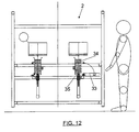
- the machine of the invention is designed with a modular concept by means of modules which may include a single bagging track or line, or two tracks. These modules can later be combined with one another in order to arrange single-track, two-track, three-track machines, etc.
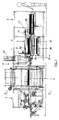
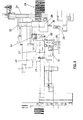
- Figure 1 shows a side elevational view of a machine, independently of the number of tracks thereof, since all of them will be in parallel, whereas Figure 2 shows a plan view of the machine of Figure 1 corresponding to a two-track module.
- each one of the tracks of the machine of the invention includes, as in the machine of the prior art, a lid cluster former, with reference number 1, a bag storage area, with reference number 2, a unit with means for removing and positioning the bags, with general reference number 3, and a unit with means for inserting the lid clusters into the bags and for the closure thereof, with general reference number 4.
- the machine of the invention includes, between the lid cluster former 1 and the inserter 4 for inserting said clusters into bags, a deposit or storage area 5 in charge of controlling the lid cluster supply to the inserter 4.
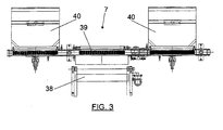
- a centralized collection system 6, Figure 2, or else a controlling deposit or storage area system 7, can be arranged at the outlet of the machine where the closed bags with the lid clusters are received, as is shown in Figure 3 for a two-track machine.
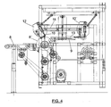
- the lid cluster former 1 comprises, as can be seen best in Figure 4, a horizontal conveyor belt 8 in charge of receiving the lids, which can have a length of 500 mm for example, which moves the lids in horizontal position and with a given spacing therebetween.
- This conveyor belt delivers the lids to a rotating wheel 8' receiving the lids in horizontal position and conveying and rotating them 90° until placing them approximately in the vertical position, in which it delivers and groups them in stack form in a magnetic channel 9.
- Lid counting is carried out on the wheel 8' and once the stack includes the pre-established lid number, a cutter or blade 10 which is assembled and can be shifted along a guide 11 parallel to the channel 9 and located above the same begins to operate.
- This cutter or blade 10 acts as a lid stack dividing element, forming clusters which are pushed by the blade itself along the channel 9, as the head 12 of said blade shifts along the guide 11 until a position 12' in which the inserter 14, which includes a compactor 13, begins to operate and is shifted to the end position 14', shifting the lid cluster to the filling and closing area 4 when the rest of the machine is operating normally.
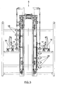
- the lid inserter 14 will place the cluster in the deposit 5, which includes a series of receiving stations 16 which are arranged in levels vertically shiftable from a position in which both the collection of clusters coming from the magnetic field 9 and the delivery of clusters to insertion area 4 for inserting clusters in the bags occur, being possible to select in any case the direct passage of the lid clusters from the magnetic channel to the lid inserter or through the deposit, depending on the operating circumstances of the rest of the machine, as has been indicated.
- the means for extracting and shifting the bags from the storage area 2 include a set of guides 17 running above the bagging line 18, in which guides there is assembled a bag extractor 19, shiftable along said guides by means of a cylinder between a rear position on the bag storage area 2 and a front position in which the bag opening and holding will be carried out, as will be explained in reference to Figures 6 to 11.
- the machine of the invention includes two cylinders 19 and 20 for the holding of the bags.
- the cylinder 19 which bears a tongue 22 that is inserted in the bag above the lower wall thereof, is actuated.
- This tongue will act as a runner to subsequently facilitate entry of the lid cluster in the bag.
- the cylinder 20 is actuated, moving upwards and pressing against the lower wall of the bag between the tongue 22 and the head of the cylinder 20, the bag thus being secured.
- bag opening is performed by means of an air jet supplied through an adjustable nozzle 41, and once the bag is open the cone nozzle 21 advances to position 21', being inserted in said bag.
- the lids can be inserted in the bag, as described in the main patent, the compaction cylinders 23, Figures 7 and 8, later acting. These cylinders act in a converging position, remarkably tangent to the front section of the lid cluster 24, acting as members for cluster retention and compaction against a rear stop 25, Figures 1 and 2, coinciding with the machine described in the main patent.
- Figure 7 it can be seen how the bag 24 is supported at the lower portion by retractable arms 44.
- Two cylinders 25 and 26 forming an L, the second of which has a folder arm 27, have been arranged for closure of the bag once the lid cluster 24 has been inserted therein.
- the bringing closer together or separation of the cylinder 25 and arm 27 from the bag 28 containing the lid cluster is achieved by means of the cylinder 25.
- a first bag folding operation is carried out, said arm acting as a guillotine.
- the cylinder and arm 27 in the position of Figure 10 and according to that described in the main patent, it has a lower roller 30 by means of which a second folding is carried out, the closing of the bag being finished with an end cylinder 42, Figure 1.
- one of the sides 33 in the bag storage area 2 has been designed as a collapsible panel to facilitate positioning of the bags 34 and their placement on a raisable-bottom platform 35.
- the machine of the invention can have a single central collection 36 at the outlet of the closed bags containing the lid cluster, as shown in Figure 2, in which case each track of the module will have its own encoding and labeling system for the purpose of not losing product traceability.
- a collector for each track can also be arranged, as shown in Figure 3, in which two collectors 40 are arranged for a two-track machine.
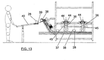
- Figure 13 shows a front elevational view of the closed bag collector.
- a distributor system acts which opens the retractable arms 44 and drops the cluster into an output deposit 36 in vertical chamber, which has gates 45 that can be actuated by means of cylinders to retain or allow the bags 28 to drop down to the buckets 38 passing underneath, dragged by the conveyor belt 37.
- This deposit has the purpose of storing the clusters while waiting, if necessary, for the conveyor belt 37 with buckets 38 to collect the clusters 28 and carry them to a distribution conveyer belt 39 from where they reach the delivery tray 40.
- the conveyer belt 39 will leave each cluster in the corresponding tray 40, Figure 3, as each one is identified with a track of the machine, such that there is correct product traceability from start to finish.
Landscapes
- Engineering & Computer Science (AREA)
- Mechanical Engineering (AREA)
- Auxiliary Devices For And Details Of Packaging Control (AREA)
- Basic Packing Technique (AREA)
- Closing Of Containers (AREA)
- Supplying Of Containers To The Packaging Station (AREA)
- Making Paper Articles (AREA)
Claims (10)
- Automatische Beutelabfüllmaschine mit grundlegenden und leicht zu öffnenden Verschlüsseln in selbstklebenden Papierbeuteln, wobei die Maschine eine Verschlussballenformeinrichtung (1), einen Beutelaufbewahrungsbereich (2) und eine Einrichtung (3) zum Herausziehen und Positionieren der Beutel umfasst sowie eine Einrichtung (4) zum Einführen der Verschlussballen in die Beutel und zum Verschließen dieser, dadurch gekennzeichnet, dass die Maschine ferner ein Lager (5) zwischen der Verschlussballenformeinrichtung (1) und der Einrichtung zum Einfügen der genannten Ballen in die Beutel aufweist, die dafür zuständig ist, die Verschlussballenzufuhr zu regeln; und wobei die Verschlussballenformeinrichtung (1) ein horizontales Förderband (8) umfasst, durch das die Verschlüsse mit einem bestimmten Zwischenabstand zwischen diesen transportiert werden, mit einem Drehrad (8'), das die Verschlüsse von dem Förderband (8) aufnimmt und diese in Stapelform zusammenfasst, mit einem Teiler zum Teilen des Stapels in Ballen, einschließlich einer vorbestimmten Anzahl von Verschlüssen, und mit einem magnetischen Kanal (9), entlang welchem die Ballen für ihre Zufuhr an die Verschlusseinführungseinrichtung durch das genannte Lager verschoben werden; und wobei die Einrichtung zum Bilden und Verschließen der Beutel ein erstes Paar positionierter Beutelhaltezylinder (19, 20) aufweist, die mit einer Einrichtung zum Führen der Verschlüsse in den Beutel und zum Halten des genannten Beutels versehen sind, mit einer Einrichtung zum Öffnen der Beutel, mit einem zweiten Paar von Halte- und Kompaktierungszylindern (23) zum Kompaktieren der Verschlüsse in dem Beutel, und mit einer Beutelfaltzylindereinheit, die aus zwei Zylindern (25, 26) besteht, die ein L bilden, das mittels einer Guillotine (27) so fungiert, dass ein erstes Falten des Beutels ausgeführt wird, und mit einer Walze (30) für ein zweites Falten des Beutels und das letztendliche Verschließen desselben.
- Automatische Beutelabfüllmaschine nach Anspruch 1, dadurch gekennzeichnet, dass das Drehrad (8') der Verschlussballenformeinrichtung die Verschlüsse von dem Förderband (8) an der horizontalen Position aufnimmt und diese um 90° zieht und dreht, bis sie ungefähr an einer vertikalen Position angeordnet sind, an der sie einem magnetischen Kanal (9) für die Stapelbildung zugeführt werden, wobei das Drehrad (8') einen Verschlussstapelschneider oder eine Verschlussstapelklinge (10) aufweist.
- Automatische Beutelabfüllmaschine nach Anspruch 1, dadurch gekennzeichnet, dass der Verschlussstapelschneider (10) eine Führung (11) parallel zu dem magnetischen Kanal (9) umfasst, angeordnet oberhalb des genannten Kanals, und mit einer an der genannten Führung (11) montierten Verschlussanzahlbegrenzungseinrichtung, die entlang ihrer Länge verschoben werden kann; wobei der genannte Schneider (10) in dem Bereich des Drehrads (8') arbeitet, wenn der Verschlussstapel die vorher festgelegte Anzahl von Verschlüssen aufweist, und wobei sie entlang der Führung (11) verschoben wird, wobei der Verschlussballen (24) zu einer Verschlusseinführungseinrichtung (14) gezogen wird.
- Automatische Beutelabfüllmaschine nach Anspruch 1, dadurch gekennzeichnet, dass das Lager (5), das für die Regelung der Verschlussballenzufuhr zuständig ist, eine Reihe von Verschlussballen-Aufnahmestationen (15) umfasst, die in Ebenen angeordnet sind, die vertikal von einer Position verschiebbar sind, worin die Aufnahme der von dem magnetischen Kanal (11) für die Verschlussballenformeinrichtung (1) kommenden Ballen und die Zufuhr der Ballen an die Verschlusseinführungseinrichtung (1) erfolgt, wobei der Verlauf der Verschlussballen (24) direkt von dem magnetischen Kanal (11) zu der Verschlusseinführungseinrichtung (14) oder der Verlauf durch das Lager (5) ausgewählt werden kann.
- Automatische Beutelabfüllmaschine nach Anspruch 1, dadurch gekennzeichnet, dass das erste Paar von Zylindern (19, 20) der Beutelbildungseinrichtung einen ersten horizontal arbeitenden Zylinder (19) aufweist, der eine Zunge (22) aufweist, die in einen positionierten Beutel (28) eingeführt werden kann, um als ein Läufer zu fungieren, um die Einführung der Verschlussballen in den Beutel (28) zu führen, und mit einem zweiten unteren, vertikal arbeitenden Zylinder (20), der die untere Wand des Beutels (28) an den genannten Streifen drücken und halten kann.
- Automatische Beutelabfüllmaschine nach Anspruch 1, dadurch gekennzeichnet, dass die Einrichtung zum Öffnen der Beutel (28) eine Düse (41) aufweist, deren Auslass in Richtung der Öffnung eines positionierten Beutels ausgerichtet ist; wobei durch die Düse (41) ein Luftstrom in Richtung der Innenseite des Beutels (28) zugeführt wird.
- Automatische Beutelabfüllmaschine nach Anspruch 1, dadurch gekennzeichnet, dass die Zylinder (23) des zweiten Paars der Halte- und Kompaktierungszylinder mit einem Zylinder auf jeder Seite des Beutels (28) angeordnet sind, der den Verschlussballen (24) aufweist, wobei die Zylinder (23) in konvergierende Richtungen an der Öffnung des genannten Beutels wirken; tangential zu der Vorderseite des Verschlussballens (24) für deren Zurückhalten und Kompression an einen oberen stützenden Anschlag des Beutels (28).
- Automatische Beutelabfüllmaschine nach Anspruch 1, dadurch gekennzeichnet, dass die beiden Zylinder (25, 26) ein L der ersten Faltzylindereinheit bilden, wobei der erste Zylinder (25) als eine Einrichtung wirkt, welche den zweiten Zylinder (26) näher bringt, wobei der zweite Zylinder der Einheit mit einem Arm (27) bereitgestellt ist, der parallel zu dem ersten Zylinder (25) ist, und der in die Richtung verschiebbar ist, die senkrecht zu der Achse des Beutels (28) und des Verschlussballens (24) ist.
- Automatische Beutelabfüllmaschine nach Anspruch 1, dadurch gekennzeichnet, dass diese ein Lager (5) umfasst, das für die Aufnahme und das Aufbewahren der verschlossenen Beutel (28) zuständig ist, welche einen Verschlussballen (24) aufweisen; wobei eine Sammelfördereinrichtung diese von dort sammelt und sie zu einer Verteilungsfördereinrichtung transportiert.
- Automatische Beutelabfüllmaschine nach Anspruch 1, dadurch gekennzeichnet, dass der Beutelaufbewahrungsbereich (2) eine kollabierbare Wand mit Scharnier auf einer seiner Seiten aufweist, die als Basisplattform (35) dient, um die Beutel zu platzieren und anzuordnen, von wo diese in Stapelform auf dem Boden des Aufbewahrungsbereichs eingeführt werden.
Priority Applications (1)
| Application Number | Priority Date | Filing Date | Title |
|---|---|---|---|
| PL05380012T PL1559650T3 (pl) | 2004-01-23 | 2005-01-24 | Automatyczna maszyna workująca pokrywki w samoklejące worki |
Applications Claiming Priority (2)
| Application Number | Priority Date | Filing Date | Title |
|---|---|---|---|
| ES200400140 | 2004-01-23 | ||
| ES200400140A ES2249967B1 (es) | 2003-05-06 | 2004-01-23 | Mejoras en la patente no.200301023, relativa a una maquina embolsadora automatica de tapas basicas y de facil apertura en bolsas de papel autoencolante. |
Publications (2)
| Publication Number | Publication Date |
|---|---|
| EP1559650A1 EP1559650A1 (de) | 2005-08-03 |
| EP1559650B1 true EP1559650B1 (de) | 2007-02-28 |
Family
ID=34639546
Family Applications (1)
| Application Number | Title | Priority Date | Filing Date |
|---|---|---|---|
| EP05380012A Expired - Lifetime EP1559650B1 (de) | 2004-01-23 | 2005-01-24 | Vorrichtung zum automatischen Verpacken von Deckeln in selbstklebende Beutel |
Country Status (6)
| Country | Link |
|---|---|
| EP (1) | EP1559650B1 (de) |
| AT (1) | ATE355223T1 (de) |
| DE (1) | DE602005000604D1 (de) |
| DK (1) | DK1559650T3 (de) |
| PL (1) | PL1559650T3 (de) |
| PT (1) | PT1559650E (de) |
Cited By (1)
| Publication number | Priority date | Publication date | Assignee | Title |
|---|---|---|---|---|
| TWI513843B (zh) * | 2012-01-12 | 2015-12-21 | Hon Hai Prec Ind Co Ltd | 蓋體 |
Families Citing this family (2)
| Publication number | Priority date | Publication date | Assignee | Title |
|---|---|---|---|---|
| BR102014030304B1 (pt) | 2014-12-04 | 2022-04-05 | Ball Beverage Can South America S/A | Processo de gerenciamento de conjunto de tampas empilhadas e inseridas em uma embalagem, dispositivo de transporte para transportar um conjunto de tampas empilhadas e inseridas em uma embalagem e sistema de produção de conjuntos de tampas paletizados |
| BR102014030315B1 (pt) | 2014-12-04 | 2021-09-08 | Ball Beverage Can South America S/A | Processo de embalagem de um conjunto de tampas empilhadas e dispositivo de embalagem para conjuntos de tampas empilhadas |
Family Cites Families (5)
| Publication number | Priority date | Publication date | Assignee | Title |
|---|---|---|---|---|
| NL8501520A (nl) * | 1985-05-28 | 1986-12-16 | Thomassen & Drijver | Inrichting en werkwijze voor het verpakken van een rij schijfvormige elementen, en de vervaardigde verpakking. |
| DE3729271A1 (de) * | 1987-09-02 | 1989-03-23 | Schmalbach Lubeca | Vorrichtung zum verpacken zylindrischer straenge aus einer vielzahl scheibenfoermiger werkstuecke |
| US5119617A (en) * | 1991-01-16 | 1992-06-09 | Fleetwood Systems Inc. | Multi-lane infeed counter/bagger |
| US5863177A (en) * | 1996-10-02 | 1999-01-26 | Cbw Automation, Inc. | Apparatus and method for handling lids |
| US6547057B1 (en) * | 2000-06-05 | 2003-04-15 | Cbw Automation, Inc. | Apparatus and process for handling circular articles |
-
2005
- 2005-01-24 AT AT05380012T patent/ATE355223T1/de not_active IP Right Cessation
- 2005-01-24 DE DE602005000604T patent/DE602005000604D1/de not_active Expired - Lifetime
- 2005-01-24 PT PT05380012T patent/PT1559650E/pt unknown
- 2005-01-24 EP EP05380012A patent/EP1559650B1/de not_active Expired - Lifetime
- 2005-01-24 PL PL05380012T patent/PL1559650T3/pl unknown
- 2005-01-24 DK DK05380012T patent/DK1559650T3/da active
Cited By (1)
| Publication number | Priority date | Publication date | Assignee | Title |
|---|---|---|---|---|
| TWI513843B (zh) * | 2012-01-12 | 2015-12-21 | Hon Hai Prec Ind Co Ltd | 蓋體 |
Also Published As
| Publication number | Publication date |
|---|---|
| DE602005000604D1 (de) | 2007-04-12 |
| PL1559650T3 (pl) | 2007-08-31 |
| EP1559650A1 (de) | 2005-08-03 |
| DK1559650T3 (da) | 2007-07-02 |
| PT1559650E (pt) | 2007-06-01 |
| ATE355223T1 (de) | 2006-03-15 |
Similar Documents
| Publication | Publication Date | Title |
|---|---|---|
| KR101212307B1 (ko) | 분체 자동 개포장치 | |
| US3812273A (en) | Method for the mechanical preparation of individual cups of filtered coffee | |
| US5203953A (en) | Process and apparatus for conveying labels to be transferred to a (cigarette) pack | |
| JP6082000B2 (ja) | 1つの容器が他の容器の内側にある少なくとも2つの容器を各々が備えた硬質パケットを製造するための包装機及び方法 | |
| WO1997042079A1 (en) | Method and apparatus for packaging series of articles in different formations | |
| CA1097279A (en) | Apparatus for filling containers with articles | |
| JPH0834413A (ja) | フォイルチューブ包装体の切断兼積重ね装置 | |
| CN105691660A (zh) | 一种茶叶包装机 | |
| KR100857204B1 (ko) | 패키지 포장장치 및 포장방법 | |
| AU769047B2 (en) | Device for producing and withdrawing stacks of plastic bags, especially bags for automatic machines | |
| CZ279055B6 (en) | Packing machine | |
| EP1559650B1 (de) | Vorrichtung zum automatischen Verpacken von Deckeln in selbstklebende Beutel | |
| MX2015004996A (es) | Metodo y dispositivo para el manejo de articulos de higiene. | |
| CA2056719A1 (en) | Collating apparatus | |
| EP2604527B1 (de) | Verfahren und Maschine zur Herstellung von Beuteln mit Fasermaterial | |
| EP2604528B1 (de) | Maschine zur Herstellung von Beuteln mit Fasermaterial | |
| US6779321B1 (en) | Machine and method for bagging elongated produce | |
| EP2604526B1 (de) | Verfahren und Maschine zur Herstellung von Beuteln mit Fasermaterial | |
| CN217496785U (zh) | 一种新型高效大容量茶叶自动包装机 | |
| CH700070B1 (en) | Machine for the preparation and packaging of strips impregnated with a perfumed essence. | |
| US20240367827A1 (en) | Method and equipment for filling bags with a deaerated amount of product, with additional deaerator or compaction | |
| EP2604530A1 (de) | Verfahren und Maschine zur Herstellung von Beuteln mit Fasermaterial | |
| CN109920125A (zh) | 微型现钞处理系统 | |
| CN211563554U (zh) | 一种运用于点胶机的输送装置 | |
| CN103130014A (zh) | 一种纸币取出装置 |
Legal Events
| Date | Code | Title | Description |
|---|---|---|---|
| PUAI | Public reference made under article 153(3) epc to a published international application that has entered the european phase |
Free format text: ORIGINAL CODE: 0009012 |
|
| AK | Designated contracting states |
Kind code of ref document: A1 Designated state(s): AT BE BG CH CY CZ DE DK EE ES FI FR GB GR HU IE IS IT LI LT LU MC NL PL PT RO SE SI SK TR |
|
| AX | Request for extension of the european patent |
Extension state: AL BA HR LV MK YU |
|
| 17P | Request for examination filed |
Effective date: 20050913 |
|
| AKX | Designation fees paid |
Designated state(s): AT BE BG CH CY CZ DE DK EE ES FI FR GB GR HU IE IS IT LI LT LU MC NL PL PT RO SE SI SK TR |
|
| AXX | Extension fees paid |
Extension state: MK Payment date: 20050913 Extension state: YU Payment date: 20050913 Extension state: BA Payment date: 20050913 Extension state: AL Payment date: 20050913 Extension state: HR Payment date: 20050913 Extension state: LV Payment date: 20050913 |
|
| GRAP | Despatch of communication of intention to grant a patent |
Free format text: ORIGINAL CODE: EPIDOSNIGR1 |
|
| GRAS | Grant fee paid |
Free format text: ORIGINAL CODE: EPIDOSNIGR3 |
|
| GRAA | (expected) grant |
Free format text: ORIGINAL CODE: 0009210 |
|
| AK | Designated contracting states |
Kind code of ref document: B1 Designated state(s): AT BE BG CH CY CZ DE DK EE ES FI FR GB GR HU IE IS IT LI LT LU MC NL PL PT RO SE SI SK TR |
|
| AX | Request for extension of the european patent |
Extension state: AL BA HR LV MK YU |
|
| PG25 | Lapsed in a contracting state [announced via postgrant information from national office to epo] |
Ref country code: SI Free format text: LAPSE BECAUSE OF FAILURE TO SUBMIT A TRANSLATION OF THE DESCRIPTION OR TO PAY THE FEE WITHIN THE PRESCRIBED TIME-LIMIT Effective date: 20070228 Ref country code: FI Free format text: LAPSE BECAUSE OF FAILURE TO SUBMIT A TRANSLATION OF THE DESCRIPTION OR TO PAY THE FEE WITHIN THE PRESCRIBED TIME-LIMIT Effective date: 20070228 Ref country code: BE Free format text: LAPSE BECAUSE OF FAILURE TO SUBMIT A TRANSLATION OF THE DESCRIPTION OR TO PAY THE FEE WITHIN THE PRESCRIBED TIME-LIMIT Effective date: 20070228 Ref country code: AT Free format text: LAPSE BECAUSE OF FAILURE TO SUBMIT A TRANSLATION OF THE DESCRIPTION OR TO PAY THE FEE WITHIN THE PRESCRIBED TIME-LIMIT Effective date: 20070228 Ref country code: LI Free format text: LAPSE BECAUSE OF FAILURE TO SUBMIT A TRANSLATION OF THE DESCRIPTION OR TO PAY THE FEE WITHIN THE PRESCRIBED TIME-LIMIT Effective date: 20070228 Ref country code: CH Free format text: LAPSE BECAUSE OF FAILURE TO SUBMIT A TRANSLATION OF THE DESCRIPTION OR TO PAY THE FEE WITHIN THE PRESCRIBED TIME-LIMIT Effective date: 20070228 |
|
| REG | Reference to a national code |
Ref country code: GB Ref legal event code: FG4D |
|
| REG | Reference to a national code |
Ref country code: CH Ref legal event code: EP |
|
| REF | Corresponds to: |
Ref document number: 602005000604 Country of ref document: DE Date of ref document: 20070412 Kind code of ref document: P |
|
| REG | Reference to a national code |
Ref country code: IE Ref legal event code: FG4D |
|
| PG25 | Lapsed in a contracting state [announced via postgrant information from national office to epo] |
Ref country code: BG Free format text: LAPSE BECAUSE OF FAILURE TO SUBMIT A TRANSLATION OF THE DESCRIPTION OR TO PAY THE FEE WITHIN THE PRESCRIBED TIME-LIMIT Effective date: 20070528 |
|
| PG25 | Lapsed in a contracting state [announced via postgrant information from national office to epo] |
Ref country code: SE Free format text: LAPSE BECAUSE OF FAILURE TO SUBMIT A TRANSLATION OF THE DESCRIPTION OR TO PAY THE FEE WITHIN THE PRESCRIBED TIME-LIMIT Effective date: 20070531 |
|
| REG | Reference to a national code |
Ref country code: PT Ref legal event code: SC4A Free format text: AVAILABILITY OF NATIONAL TRANSLATION Effective date: 20070523 |
|
| PG25 | Lapsed in a contracting state [announced via postgrant information from national office to epo] |
Ref country code: ES Free format text: LAPSE BECAUSE OF FAILURE TO SUBMIT A TRANSLATION OF THE DESCRIPTION OR TO PAY THE FEE WITHIN THE PRESCRIBED TIME-LIMIT Effective date: 20070608 |
|
| PG25 | Lapsed in a contracting state [announced via postgrant information from national office to epo] |
Ref country code: IS Free format text: LAPSE BECAUSE OF FAILURE TO SUBMIT A TRANSLATION OF THE DESCRIPTION OR TO PAY THE FEE WITHIN THE PRESCRIBED TIME-LIMIT Effective date: 20070628 |
|
| REG | Reference to a national code |
Ref country code: DK Ref legal event code: T3 |
|
| REG | Reference to a national code |
Ref country code: HU Ref legal event code: AG4A Ref document number: E001802 Country of ref document: HU |
|
| REG | Reference to a national code |
Ref country code: CH Ref legal event code: PL Ref country code: PL Ref legal event code: T3 |
|
| PG25 | Lapsed in a contracting state [announced via postgrant information from national office to epo] |
Ref country code: SK Free format text: LAPSE BECAUSE OF FAILURE TO SUBMIT A TRANSLATION OF THE DESCRIPTION OR TO PAY THE FEE WITHIN THE PRESCRIBED TIME-LIMIT Effective date: 20070228 |
|
| PG25 | Lapsed in a contracting state [announced via postgrant information from national office to epo] |
Ref country code: CZ Free format text: LAPSE BECAUSE OF FAILURE TO SUBMIT A TRANSLATION OF THE DESCRIPTION OR TO PAY THE FEE WITHIN THE PRESCRIBED TIME-LIMIT Effective date: 20070228 Ref country code: RO Free format text: LAPSE BECAUSE OF FAILURE TO SUBMIT A TRANSLATION OF THE DESCRIPTION OR TO PAY THE FEE WITHIN THE PRESCRIBED TIME-LIMIT Effective date: 20070228 |
|
| PLBE | No opposition filed within time limit |
Free format text: ORIGINAL CODE: 0009261 |
|
| STAA | Information on the status of an ep patent application or granted ep patent |
Free format text: STATUS: NO OPPOSITION FILED WITHIN TIME LIMIT |
|
| PG25 | Lapsed in a contracting state [announced via postgrant information from national office to epo] |
Ref country code: DE Free format text: LAPSE BECAUSE OF FAILURE TO SUBMIT A TRANSLATION OF THE DESCRIPTION OR TO PAY THE FEE WITHIN THE PRESCRIBED TIME-LIMIT Effective date: 20070530 |
|
| 26N | No opposition filed |
Effective date: 20071129 |
|
| PG25 | Lapsed in a contracting state [announced via postgrant information from national office to epo] |
Ref country code: LT Free format text: LAPSE BECAUSE OF FAILURE TO SUBMIT A TRANSLATION OF THE DESCRIPTION OR TO PAY THE FEE WITHIN THE PRESCRIBED TIME-LIMIT Effective date: 20070228 |
|
| PG25 | Lapsed in a contracting state [announced via postgrant information from national office to epo] |
Ref country code: GR Free format text: LAPSE BECAUSE OF FAILURE TO SUBMIT A TRANSLATION OF THE DESCRIPTION OR TO PAY THE FEE WITHIN THE PRESCRIBED TIME-LIMIT Effective date: 20070529 |
|
| PG25 | Lapsed in a contracting state [announced via postgrant information from national office to epo] |
Ref country code: MC Free format text: LAPSE BECAUSE OF NON-PAYMENT OF DUE FEES Effective date: 20080131 |
|
| PG25 | Lapsed in a contracting state [announced via postgrant information from national office to epo] |
Ref country code: IE Free format text: LAPSE BECAUSE OF NON-PAYMENT OF DUE FEES Effective date: 20080124 Ref country code: EE Free format text: LAPSE BECAUSE OF FAILURE TO SUBMIT A TRANSLATION OF THE DESCRIPTION OR TO PAY THE FEE WITHIN THE PRESCRIBED TIME-LIMIT Effective date: 20070228 |
|
| PG25 | Lapsed in a contracting state [announced via postgrant information from national office to epo] |
Ref country code: CY Free format text: LAPSE BECAUSE OF FAILURE TO SUBMIT A TRANSLATION OF THE DESCRIPTION OR TO PAY THE FEE WITHIN THE PRESCRIBED TIME-LIMIT Effective date: 20070228 |
|
| GBPC | Gb: european patent ceased through non-payment of renewal fee |
Effective date: 20090124 |
|
| PG25 | Lapsed in a contracting state [announced via postgrant information from national office to epo] |
Ref country code: GB Free format text: LAPSE BECAUSE OF NON-PAYMENT OF DUE FEES Effective date: 20090124 |
|
| PG25 | Lapsed in a contracting state [announced via postgrant information from national office to epo] |
Ref country code: LU Free format text: LAPSE BECAUSE OF NON-PAYMENT OF DUE FEES Effective date: 20080124 |
|
| PG25 | Lapsed in a contracting state [announced via postgrant information from national office to epo] |
Ref country code: TR Free format text: LAPSE BECAUSE OF FAILURE TO SUBMIT A TRANSLATION OF THE DESCRIPTION OR TO PAY THE FEE WITHIN THE PRESCRIBED TIME-LIMIT Effective date: 20070228 |
|
| REG | Reference to a national code |
Ref country code: FR Ref legal event code: PLFP Year of fee payment: 12 |
|
| REG | Reference to a national code |
Ref country code: FR Ref legal event code: PLFP Year of fee payment: 13 |
|
| REG | Reference to a national code |
Ref country code: FR Ref legal event code: PLFP Year of fee payment: 14 |
|
| PGFP | Annual fee paid to national office [announced via postgrant information from national office to epo] |
Ref country code: NL Payment date: 20180124 Year of fee payment: 14 |
|
| PGFP | Annual fee paid to national office [announced via postgrant information from national office to epo] |
Ref country code: DK Payment date: 20180125 Year of fee payment: 14 |
|
| PGFP | Annual fee paid to national office [announced via postgrant information from national office to epo] |
Ref country code: IT Payment date: 20180129 Year of fee payment: 14 Ref country code: PT Payment date: 20180123 Year of fee payment: 14 Ref country code: FR Payment date: 20180129 Year of fee payment: 14 Ref country code: HU Payment date: 20180220 Year of fee payment: 14 Ref country code: PL Payment date: 20180124 Year of fee payment: 14 |
|
| REG | Reference to a national code |
Ref country code: DK Ref legal event code: EBP Effective date: 20190131 |
|
| REG | Reference to a national code |
Ref country code: NL Ref legal event code: MM Effective date: 20190201 |
|
| PG25 | Lapsed in a contracting state [announced via postgrant information from national office to epo] |
Ref country code: PT Free format text: LAPSE BECAUSE OF NON-PAYMENT OF DUE FEES Effective date: 20190724 Ref country code: FR Free format text: LAPSE BECAUSE OF NON-PAYMENT OF DUE FEES Effective date: 20190131 Ref country code: NL Free format text: LAPSE BECAUSE OF NON-PAYMENT OF DUE FEES Effective date: 20190201 |
|
| PG25 | Lapsed in a contracting state [announced via postgrant information from national office to epo] |
Ref country code: HU Free format text: LAPSE BECAUSE OF NON-PAYMENT OF DUE FEES Effective date: 20190125 |
|
| PG25 | Lapsed in a contracting state [announced via postgrant information from national office to epo] |
Ref country code: DK Free format text: LAPSE BECAUSE OF NON-PAYMENT OF DUE FEES Effective date: 20190131 |
|
| PG25 | Lapsed in a contracting state [announced via postgrant information from national office to epo] |
Ref country code: IT Free format text: LAPSE BECAUSE OF NON-PAYMENT OF DUE FEES Effective date: 20190124 |
|
| PG25 | Lapsed in a contracting state [announced via postgrant information from national office to epo] |
Ref country code: PL Free format text: LAPSE BECAUSE OF NON-PAYMENT OF DUE FEES Effective date: 20190124 |