EP1559650B1 - Automatic bagging machine of lids in self-adhesive bags - Google Patents
Automatic bagging machine of lids in self-adhesive bags Download PDFInfo
- Publication number
- EP1559650B1 EP1559650B1 EP05380012A EP05380012A EP1559650B1 EP 1559650 B1 EP1559650 B1 EP 1559650B1 EP 05380012 A EP05380012 A EP 05380012A EP 05380012 A EP05380012 A EP 05380012A EP 1559650 B1 EP1559650 B1 EP 1559650B1
- Authority
- EP
- European Patent Office
- Prior art keywords
- lid
- bag
- bags
- cluster
- lids
- Prior art date
- Legal status (The legal status is an assumption and is not a legal conclusion. Google has not performed a legal analysis and makes no representation as to the accuracy of the status listed.)
- Expired - Lifetime
Links
- 239000000853 adhesive Substances 0.000 title claims description 3
- 238000003860 storage Methods 0.000 claims description 15
- 230000015572 biosynthetic process Effects 0.000 claims description 5
- 238000005056 compaction Methods 0.000 claims description 5
- 238000003780 insertion Methods 0.000 claims description 4
- 230000037431 insertion Effects 0.000 claims description 4
- 238000009826 distribution Methods 0.000 claims description 3
- 230000014759 maintenance of location Effects 0.000 claims description 2
- 230000006835 compression Effects 0.000 claims 1
- 238000007906 compression Methods 0.000 claims 1
- 238000004519 manufacturing process Methods 0.000 description 6
- 239000003292 glue Substances 0.000 description 2
- 230000006978 adaptation Effects 0.000 description 1
- 238000010438 heat treatment Methods 0.000 description 1
- 238000002372 labelling Methods 0.000 description 1
- 239000000463 material Substances 0.000 description 1
- 239000002184 metal Substances 0.000 description 1
- 238000000034 method Methods 0.000 description 1
- 238000002360 preparation method Methods 0.000 description 1
- 238000003825 pressing Methods 0.000 description 1
- 238000007789 sealing Methods 0.000 description 1
- 238000000926 separation method Methods 0.000 description 1
Images


Classifications
-
- B—PERFORMING OPERATIONS; TRANSPORTING
- B65—CONVEYING; PACKING; STORING; HANDLING THIN OR FILAMENTARY MATERIAL
- B65B—MACHINES, APPARATUS OR DEVICES FOR, OR METHODS OF, PACKAGING ARTICLES OR MATERIALS; UNPACKING
- B65B5/00—Packaging individual articles in containers or receptacles, e.g. bags, sacks, boxes, cartons, cans, jars
- B65B5/06—Packaging groups of articles, the groups being treated as single articles
- B65B5/067—Packaging groups of articles, the groups being treated as single articles in bags
-
- B—PERFORMING OPERATIONS; TRANSPORTING
- B65—CONVEYING; PACKING; STORING; HANDLING THIN OR FILAMENTARY MATERIAL
- B65B—MACHINES, APPARATUS OR DEVICES FOR, OR METHODS OF, PACKAGING ARTICLES OR MATERIALS; UNPACKING
- B65B35/00—Supplying, feeding, arranging or orientating articles to be packaged
- B65B35/30—Arranging and feeding articles in groups
- B65B35/44—Arranging and feeding articles in groups by endless belts or chains
-
- B—PERFORMING OPERATIONS; TRANSPORTING
- B65—CONVEYING; PACKING; STORING; HANDLING THIN OR FILAMENTARY MATERIAL
- B65B—MACHINES, APPARATUS OR DEVICES FOR, OR METHODS OF, PACKAGING ARTICLES OR MATERIALS; UNPACKING
- B65B65/00—Details peculiar to packaging machines and not otherwise provided for; Arrangements of such details
- B65B65/003—Packaging lines, e.g. general layout
-
- B—PERFORMING OPERATIONS; TRANSPORTING
- B65—CONVEYING; PACKING; STORING; HANDLING THIN OR FILAMENTARY MATERIAL
- B65B—MACHINES, APPARATUS OR DEVICES FOR, OR METHODS OF, PACKAGING ARTICLES OR MATERIALS; UNPACKING
- B65B35/00—Supplying, feeding, arranging or orientating articles to be packaged
- B65B35/56—Orientating, i.e. changing the attitude of, articles, e.g. of non-uniform cross-section
-
- B—PERFORMING OPERATIONS; TRANSPORTING
- B65—CONVEYING; PACKING; STORING; HANDLING THIN OR FILAMENTARY MATERIAL
- B65B—MACHINES, APPARATUS OR DEVICES FOR, OR METHODS OF, PACKAGING ARTICLES OR MATERIALS; UNPACKING
- B65B43/00—Forming, feeding, opening or setting-up containers or receptacles in association with packaging
- B65B43/26—Opening or distending bags; Opening, erecting, or setting-up boxes, cartons, or carton blanks
- B65B43/34—Opening or distending bags; Opening, erecting, or setting-up boxes, cartons, or carton blanks by internal pressure
- B65B43/36—Opening or distending bags; Opening, erecting, or setting-up boxes, cartons, or carton blanks by internal pressure applied pneumatically
Definitions
- the present invention relates to an automatic bagging machine of basic and easy-to-open lids in self-adhesive paper bags, the machine of which is particularly applicable within the metal container manufacturing industry and generally in any production line where lids or similar materials with respect to their physical and geometric features are worked with.
- Automatic bagging machines comprising a lid cluster former, a bag storage area, means for extracting, shifting and forming the bags and means for inserting the lid clusters into the bags and closing said bags, said means being arranged practically in alignment, which simplifies the structure and operation of the machine are known in the art.
- the present invention allows on one hand to achieve a greater effectiveness in obtaining the bags filled with the lids, and on the other hand, to facilitate the adaptation of the machine to the manufacturing requirements and conditions.
- the systems for lid cluster formation, for handling the empty bags and for inserting the lid clusters into the bags, as well as the systems for folding and closing the bags and for collecting and distributing the same, are improved, all this such that handled product traceability is maintained throughout the machine.
- the machine is created with a modular concept starting from two modules, one a production track and the other one two parallel production tracks.
- These modules can be grouped, forming combinations with one track, two tracks, three tracks, four tracks, etc., taking into account that the operating principle is the same for all the tracks, which will have their own autonomy in automatic and manual operation state. It will have an end conveyor belt for this arrangement which will be responsible for collecting the clusters of the different tracks and taking them to a cluster selection and distribution module according to track of origin, acting as a controlling storage area or deposit.
- the machine of the invention includes, between the lid cluster former and the inserter of said clusters into the bags, a deposit responsible for controlling lid cluster supply.
- a deposit responsible for controlling lid cluster supply By means of this storage area, if the machine is operating normally with respect to bag collection, placement and formation, the lid clusters will go directly through the deposit, but not being stored therein, rather for their insertion into the unfolded bags.
- the lid clusters supplied by the cluster former will be stored in the deposit area, up to a certain number, later being automatically extracted for carrying out bag filling.
- the machine has means for controlling the cluster and bag delivery according to the machine operating conditions and manufacturing requirements.
- the lid cluster former comprises a horizontal conveyor belt by means of which the lids are conveyed with a given spacing between them, a rotating wheel receiving the lids from the conveyor belt and grouping them in stack form, a stack divider for dividing it into clusters including a large predetermined number of lids, and a magnetic channel along which the clusters are shifted for their delivery to the lid inserter through the previously mentioned deposit.
- the rotating wheel of the lid cluster former receives the lids from the belt in the horizontal position and drags and turns them 90° with mechanical or magnetic means until arranging them approximately in the vertical position, in which position it supplies them to the magnetic channel in stack form.
- This wheel includes a lid stack cutter or divider for cluster formation.
- the divider comprises a guide parallel to the magnetic channel, located above said channel, and a lid number limiter blade, which blade is assembled on said guide and can be shifted along the same, following the shifting of the lids from the rotating wheel and along the channel to the lid inserter. This blade acts in the area of the rotating wheel once the lid stack includes a pre-established number of lids, and it shifts along the guide, dragging or pushing the lid cluster to the lid inserter.
- the bag forming and closing means are also improved, which include a first pair of empty and positioned bag holding cylinders, provided with means for guiding the lids inside the bag and for holding said bag, means for opening the bag, a second pair of holding and compaction cylinders for compacting the lids inside the bag, and a bag folding cylinder assembly made up of two cylinders forming an L acting like a guillotine in order to carry out a first folding of the bag.
- these closing means include a second bag folding cylinder and a final bag closure cylinder.
- the machine of the invention is designed with a modular concept by means of modules which may include a single bagging track or line, or two tracks. These modules can later be combined with one another in order to arrange single-track, two-track, three-track machines, etc.
- Figure 1 shows a side elevational view of a machine, independently of the number of tracks thereof, since all of them will be in parallel, whereas Figure 2 shows a plan view of the machine of Figure 1 corresponding to a two-track module.
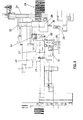
- each one of the tracks of the machine of the invention includes, as in the machine of the prior art, a lid cluster former, with reference number 1, a bag storage area, with reference number 2, a unit with means for removing and positioning the bags, with general reference number 3, and a unit with means for inserting the lid clusters into the bags and for the closure thereof, with general reference number 4.
- the machine of the invention includes, between the lid cluster former 1 and the inserter 4 for inserting said clusters into bags, a deposit or storage area 5 in charge of controlling the lid cluster supply to the inserter 4.
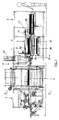
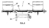
- a centralized collection system 6, Figure 2, or else a controlling deposit or storage area system 7, can be arranged at the outlet of the machine where the closed bags with the lid clusters are received, as is shown in Figure 3 for a two-track machine.
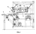
- the lid cluster former 1 comprises, as can be seen best in Figure 4, a horizontal conveyor belt 8 in charge of receiving the lids, which can have a length of 500 mm for example, which moves the lids in horizontal position and with a given spacing therebetween.
- This conveyor belt delivers the lids to a rotating wheel 8' receiving the lids in horizontal position and conveying and rotating them 90° until placing them approximately in the vertical position, in which it delivers and groups them in stack form in a magnetic channel 9.
- Lid counting is carried out on the wheel 8' and once the stack includes the pre-established lid number, a cutter or blade 10 which is assembled and can be shifted along a guide 11 parallel to the channel 9 and located above the same begins to operate.
- This cutter or blade 10 acts as a lid stack dividing element, forming clusters which are pushed by the blade itself along the channel 9, as the head 12 of said blade shifts along the guide 11 until a position 12' in which the inserter 14, which includes a compactor 13, begins to operate and is shifted to the end position 14', shifting the lid cluster to the filling and closing area 4 when the rest of the machine is operating normally.
- the lid inserter 14 will place the cluster in the deposit 5, which includes a series of receiving stations 16 which are arranged in levels vertically shiftable from a position in which both the collection of clusters coming from the magnetic field 9 and the delivery of clusters to insertion area 4 for inserting clusters in the bags occur, being possible to select in any case the direct passage of the lid clusters from the magnetic channel to the lid inserter or through the deposit, depending on the operating circumstances of the rest of the machine, as has been indicated.
- the means for extracting and shifting the bags from the storage area 2 include a set of guides 17 running above the bagging line 18, in which guides there is assembled a bag extractor 19, shiftable along said guides by means of a cylinder between a rear position on the bag storage area 2 and a front position in which the bag opening and holding will be carried out, as will be explained in reference to Figures 6 to 11.
- the machine of the invention includes two cylinders 19 and 20 for the holding of the bags.
- the cylinder 19 which bears a tongue 22 that is inserted in the bag above the lower wall thereof, is actuated.
- This tongue will act as a runner to subsequently facilitate entry of the lid cluster in the bag.
- the cylinder 20 is actuated, moving upwards and pressing against the lower wall of the bag between the tongue 22 and the head of the cylinder 20, the bag thus being secured.
- bag opening is performed by means of an air jet supplied through an adjustable nozzle 41, and once the bag is open the cone nozzle 21 advances to position 21', being inserted in said bag.
- the lids can be inserted in the bag, as described in the main patent, the compaction cylinders 23, Figures 7 and 8, later acting. These cylinders act in a converging position, remarkably tangent to the front section of the lid cluster 24, acting as members for cluster retention and compaction against a rear stop 25, Figures 1 and 2, coinciding with the machine described in the main patent.
- Figure 7 it can be seen how the bag 24 is supported at the lower portion by retractable arms 44.
- Two cylinders 25 and 26 forming an L, the second of which has a folder arm 27, have been arranged for closure of the bag once the lid cluster 24 has been inserted therein.
- the bringing closer together or separation of the cylinder 25 and arm 27 from the bag 28 containing the lid cluster is achieved by means of the cylinder 25.
- a first bag folding operation is carried out, said arm acting as a guillotine.
- the cylinder and arm 27 in the position of Figure 10 and according to that described in the main patent, it has a lower roller 30 by means of which a second folding is carried out, the closing of the bag being finished with an end cylinder 42, Figure 1.
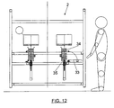
- one of the sides 33 in the bag storage area 2 has been designed as a collapsible panel to facilitate positioning of the bags 34 and their placement on a raisable-bottom platform 35.
- the machine of the invention can have a single central collection 36 at the outlet of the closed bags containing the lid cluster, as shown in Figure 2, in which case each track of the module will have its own encoding and labeling system for the purpose of not losing product traceability.
- a collector for each track can also be arranged, as shown in Figure 3, in which two collectors 40 are arranged for a two-track machine.
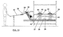
- Figure 13 shows a front elevational view of the closed bag collector.
- a distributor system acts which opens the retractable arms 44 and drops the cluster into an output deposit 36 in vertical chamber, which has gates 45 that can be actuated by means of cylinders to retain or allow the bags 28 to drop down to the buckets 38 passing underneath, dragged by the conveyor belt 37.
- This deposit has the purpose of storing the clusters while waiting, if necessary, for the conveyor belt 37 with buckets 38 to collect the clusters 28 and carry them to a distribution conveyer belt 39 from where they reach the delivery tray 40.
- the conveyer belt 39 will leave each cluster in the corresponding tray 40, Figure 3, as each one is identified with a track of the machine, such that there is correct product traceability from start to finish.
Landscapes
- Engineering & Computer Science (AREA)
- Mechanical Engineering (AREA)
- Auxiliary Devices For And Details Of Packaging Control (AREA)
- Basic Packing Technique (AREA)
- Closing Of Containers (AREA)
- Supplying Of Containers To The Packaging Station (AREA)
- Making Paper Articles (AREA)
Abstract
Description
- The present invention relates to an automatic bagging machine of basic and easy-to-open lids in self-adhesive paper bags, the machine of which is particularly applicable within the metal container manufacturing industry and generally in any production line where lids or similar materials with respect to their physical and geometric features are worked with.
- Automatic bagging machines comprising a lid cluster former, a bag storage area, means for extracting, shifting and forming the bags and means for inserting the lid clusters into the bags and closing said bags, said means being arranged practically in alignment, which simplifies the structure and operation of the machine are known in the art.
- The present invention allows on one hand to achieve a greater effectiveness in obtaining the bags filled with the lids, and on the other hand, to facilitate the adaptation of the machine to the manufacturing requirements and conditions.
- To that end according to the invention, the systems for lid cluster formation, for handling the empty bags and for inserting the lid clusters into the bags, as well as the systems for folding and closing the bags and for collecting and distributing the same, are improved, all this such that handled product traceability is maintained throughout the machine.
- With the improvements of the invention, the machine is created with a modular concept starting from two modules, one a production track and the other one two parallel production tracks.
- These modules can be grouped, forming combinations with one track, two tracks, three tracks, four tracks, etc., taking into account that the operating principle is the same for all the tracks, which will have their own autonomy in automatic and manual operation state. It will have an end conveyor belt for this arrangement which will be responsible for collecting the clusters of the different tracks and taking them to a cluster selection and distribution module according to track of origin, acting as a controlling storage area or deposit.
- On the other hand, the machine of the invention includes, between the lid cluster former and the inserter of said clusters into the bags, a deposit responsible for controlling lid cluster supply. By means of this storage area, if the machine is operating normally with respect to bag collection, placement and formation, the lid clusters will go directly through the deposit, but not being stored therein, rather for their insertion into the unfolded bags. On the other hand, if any operation problem occurs during the different bag preparation and filling operations, the lid clusters supplied by the cluster former will be stored in the deposit area, up to a certain number, later being automatically extracted for carrying out bag filling.
- Thus, in both the lid cluster supply process and in the final reception of bags with lid clusters, the machine has means for controlling the cluster and bag delivery according to the machine operating conditions and manufacturing requirements.
- According to the improvements inserted in the lid cluster former, the latter comprises a horizontal conveyor belt by means of which the lids are conveyed with a given spacing between them, a rotating wheel receiving the lids from the conveyor belt and grouping them in stack form, a stack divider for dividing it into clusters including a large predetermined number of lids, and a magnetic channel along which the clusters are shifted for their delivery to the lid inserter through the previously mentioned deposit.
- The rotating wheel of the lid cluster former receives the lids from the belt in the horizontal position and drags and turns them 90° with mechanical or magnetic means until arranging them approximately in the vertical position, in which position it supplies them to the magnetic channel in stack form. This wheel includes a lid stack cutter or divider for cluster formation. The divider comprises a guide parallel to the magnetic channel, located above said channel, and a lid number limiter blade, which blade is assembled on said guide and can be shifted along the same, following the shifting of the lids from the rotating wheel and along the channel to the lid inserter. This blade acts in the area of the rotating wheel once the lid stack includes a pre-established number of lids, and it shifts along the guide, dragging or pushing the lid cluster to the lid inserter.
- According to the invention the bag forming and closing means are also improved, which include a first pair of empty and positioned bag holding cylinders, provided with means for guiding the lids inside the bag and for holding said bag, means for opening the bag, a second pair of holding and compaction cylinders for compacting the lids inside the bag, and a bag folding cylinder assembly made up of two cylinders forming an L acting like a guillotine in order to carry out a first folding of the bag. Finally and as in the machine of the main patent, these closing means include a second bag folding cylinder and a final bag closure cylinder.
- All the features set forth as well as others of the invention as they are included in the claims are explained below in greater detail with the aid of the attached drawings in which a non-limiting embodiment example is shown.
- In the drawings:
- Figure 1 shows a side elevational view of a machine constituted according to the invention.
- Figure 2 shows a plan view of the machine of Figure 1, corresponding to a two-track module.
- Figure 3 shows a plan view of the deposit or controlling storage area of the closed and filled bags at the machine outlet.
- Figure 4 shows a side elevational view of the lid cluster former.
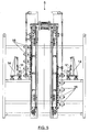
- Figure 5 shows a front elevational view of the deposit in charge of controlling the supply of lid clusters, according to the A-A direction of Figure 1.
- Figure 6 shows a side view, on a larger scale, of the area of insertion, folding and sealing of the lids in the paper bags.
- Figures 7 and 8 are a front elevational and upper plan view of the side stops of the lid cluster inserted in a paper bag.
- Figures 9 and 10 show front elevational views of two consecutive positions of the mechanism carrying out the first folding of the bags.
- Figure 11 shows a front elevational view of the heating mechanism of the glue for closing the bags.
- Figure 12 shows a side elevational view of the bag storage area.
- Figure 13 shows a front elevational view of the final closed bag collector according to line B-B of Figure 1.
- As has been indicated, the machine of the invention is designed with a modular concept by means of modules which may include a single bagging track or line, or two tracks. These modules can later be combined with one another in order to arrange single-track, two-track, three-track machines, etc.
- Figure 1 shows a side elevational view of a machine, independently of the number of tracks thereof, since all of them will be in parallel, whereas Figure 2 shows a plan view of the machine of Figure 1 corresponding to a two-track module.
- In any case, each one of the tracks of the machine of the invention includes, as in the machine of the prior art, a lid cluster former, with reference number 1, a bag storage area, with
reference number 2, a unit with means for removing and positioning the bags, withgeneral reference number 3, and a unit with means for inserting the lid clusters into the bags and for the closure thereof, withgeneral reference number 4. - The machine of the invention includes, between the lid cluster former 1 and the
inserter 4 for inserting said clusters into bags, a deposit orstorage area 5 in charge of controlling the lid cluster supply to theinserter 4. - A
centralized collection system 6, Figure 2, or else a controlling deposit orstorage area system 7, can be arranged at the outlet of the machine where the closed bags with the lid clusters are received, as is shown in Figure 3 for a two-track machine. - The lid cluster former 1 comprises, as can be seen best in Figure 4, a
horizontal conveyor belt 8 in charge of receiving the lids, which can have a length of 500 mm for example, which moves the lids in horizontal position and with a given spacing therebetween. This conveyor belt delivers the lids to a rotating wheel 8' receiving the lids in horizontal position and conveying and rotating them 90° until placing them approximately in the vertical position, in which it delivers and groups them in stack form in amagnetic channel 9. Lid counting is carried out on the wheel 8' and once the stack includes the pre-established lid number, a cutter orblade 10 which is assembled and can be shifted along aguide 11 parallel to thechannel 9 and located above the same begins to operate. This cutter orblade 10 acts as a lid stack dividing element, forming clusters which are pushed by the blade itself along thechannel 9, as thehead 12 of said blade shifts along theguide 11 until a position 12' in which theinserter 14, which includes acompactor 13, begins to operate and is shifted to the end position 14', shifting the lid cluster to the filling andclosing area 4 when the rest of the machine is operating normally. However, if any problem occurs in the collection of the bag fromstorage area 9 or in its placement and opening inarea 3, thelid inserter 14 will place the cluster in thedeposit 5, which includes a series of receivingstations 16 which are arranged in levels vertically shiftable from a position in which both the collection of clusters coming from themagnetic field 9 and the delivery of clusters toinsertion area 4 for inserting clusters in the bags occur, being possible to select in any case the direct passage of the lid clusters from the magnetic channel to the lid inserter or through the deposit, depending on the operating circumstances of the rest of the machine, as has been indicated. - As in the main patent, the means for extracting and shifting the bags from the
storage area 2 include a set ofguides 17 running above thebagging line 18, in which guides there is assembled abag extractor 19, shiftable along said guides by means of a cylinder between a rear position on thebag storage area 2 and a front position in which the bag opening and holding will be carried out, as will be explained in reference to Figures 6 to 11. - The machine of the invention includes two
cylinders cylinder 19, which bears atongue 22 that is inserted in the bag above the lower wall thereof, is actuated. This tongue will act as a runner to subsequently facilitate entry of the lid cluster in the bag. Then thecylinder 20 is actuated, moving upwards and pressing against the lower wall of the bag between thetongue 22 and the head of thecylinder 20, the bag thus being secured. Then bag opening is performed by means of an air jet supplied through anadjustable nozzle 41, and once the bag is open thecone nozzle 21 advances to position 21', being inserted in said bag. Then the lids can be inserted in the bag, as described in the main patent, thecompaction cylinders 23, Figures 7 and 8, later acting. These cylinders act in a converging position, remarkably tangent to the front section of thelid cluster 24, acting as members for cluster retention and compaction against arear stop 25, Figures 1 and 2, coinciding with the machine described in the main patent. In Figure 7, it can be seen how thebag 24 is supported at the lower portion byretractable arms 44. - Two
cylinders folder arm 27, have been arranged for closure of the bag once thelid cluster 24 has been inserted therein. The bringing closer together or separation of thecylinder 25 andarm 27 from thebag 28 containing the lid cluster is achieved by means of thecylinder 25. Once thecylinder 25 is brought closer and actuated by means of the lowering of thearm 27, as is observed in Figure 10, a first bag folding operation is carried out, said arm acting as a guillotine. Keeping the cylinder andarm 27 in the position of Figure 10 and according to that described in the main patent, it has alower roller 30 by means of which a second folding is carried out, the closing of the bag being finished with anend cylinder 42, Figure 1. - As in the case of the main patent, there is a
glue heater 31 for closing the bag, Figures 6 and 11, which is shiftable by means of rotation in order to bring it closer to thebag 28 and withdraw it once the necessary time has elapsed. - To facilitate the bag loading operation, one of the
sides 33 in thebag storage area 2 has been designed as a collapsible panel to facilitate positioning of thebags 34 and their placement on a raisable-bottom platform 35. - Otherwise, the machine of the invention can have a single
central collection 36 at the outlet of the closed bags containing the lid cluster, as shown in Figure 2, in which case each track of the module will have its own encoding and labeling system for the purpose of not losing product traceability. - A collector for each track can also be arranged, as shown in Figure 3, in which two
collectors 40 are arranged for a two-track machine. - Figure 13 shows a front elevational view of the closed bag collector. Once the bag with the lid stack is folded and sealed, a distributor system acts which opens the
retractable arms 44 and drops the cluster into anoutput deposit 36 in vertical chamber, which hasgates 45 that can be actuated by means of cylinders to retain or allow thebags 28 to drop down to thebuckets 38 passing underneath, dragged by theconveyor belt 37. This deposit has the purpose of storing the clusters while waiting, if necessary, for theconveyor belt 37 withbuckets 38 to collect theclusters 28 and carry them to adistribution conveyer belt 39 from where they reach thedelivery tray 40. Theconveyer belt 39 will leave each cluster in thecorresponding tray 40, Figure 3, as each one is identified with a track of the machine, such that there is correct product traceability from start to finish. The work of the operator in charge of the machine is facilitated by means of this arrangement since the design of the machine is more ergonomic and makes the finished cluster collection easier for their subsequent placement on a pallet. When it is not necessary to divide the bags according to the track of origin, asingle tray 40 can be arranged, as shown in Figure 1,conveyor belt 39 being eliminated in this case since thebags 28 will be dumped directly by thebuckets 38 in the tray.
Claims (10)
- An automatic bagging machine of basic and easy-to-open lids in self-adhesive paper bags, which machine comprises a lid cluster formel (1), a bag storage area (2), means (3) for extracting and positioning the bags, and means (4) for introducing the lid clusters in the bags and for the closure thereof, characterized in that it further includes a deposit (5) between the lid cluster former (1) and the inserter of said clusters into the bags which is responsible for controlling the lid cluster supply; and in that the lid cluster former (1) comprises a horizontal conveyor belt (8) by means of which the lids are conveyed with a given spacing between them, a rotating wheel (8) which receives the lids of the conveyor belt (8) and groups them in stack form, a divider for dividing the stack into clusters including a predetermined number of lids and a magnetic channel (9) along which the clusters are shifted for their delivery to the lid inserter through said deposit; and in that the means for forming and closing the bags include a first pair of positioned bag holding cylinders (19, 20) provided with means for guiding the lids into the bag and for holding said bag, means for opening the bags, a second pair of holding and compaction cylinders (23) for compacting the lids inside the bag, and a bag folding cylinder assembly made up of two cylinders (25, 26) forming an L acting by way of a guillotine (27) to carry out a first folding of the bag, and a roller (30) for a second folding of the bag and final closure thereof.
- The automatic bagging machine according to claim 1, characterized in that the rotating wheel (8') of the lid cluster former receives the lids from the conveyor (8) belt in the horizontal position and drags and turns them 90° until arranging them approximately in the vertical position in which they are fed to a magnetic channel (9) for stack formation, the rotating wheel (8') including a lid stack cutter or blade (10).
- The automatic bagging machine according to claim 1, characterized in that the lid stack cutter (10) comprises a guide (11) parallel to the magnetic channel (9) located above said channel, and a lid number limiter blade assembled on said guide (11) and can be shifted along the length thereof; said cutter (10) acts in the area of the rotating wheel (8') once the lid stack includes the pre-established lid number, and shifts along the guide (11), dragging the lid cluster (24) to a lid inserter (14).
- The automatic bagging machine according to claim 1, characterized in that the deposit (5) responsible for controlling lid cluster supply comprises a series of lid cluster receiver stations (16) which are arranged in levels that are vertically shiftable from a position, wherein the receiving of clusters coming from the magnetic channel (11) for the lid cluster formel (1) and the delivery of clusters to the lid inserter (14) takes place, the direct passing of the lid cluster (24) from the magnetic channel (11) to the lid inserter (14) or the passing through the deposit (5) being selectable.
- The automatic bagging machine according to claim 1, characterized in that the first pair of cylinders (19, 20) of the bag formation means includes a first horizontally operating cylinder (19) which incorporates a tongue (22) that can be inserted in a positioned bag (28) in order to act as a runner to guide the insertion of the lid clusters in the bag (28), and a second lower vertically operating cylinder (20) able to press and hold the lower wall of the bag (28) against said tab.
- The automatic bagging machine according to claim 1, characterised in that the means for opening the bags (28) consist of a nozzle (41) the outlet of which is aimed towards the opening of a positioned bag; through which nozzle (41) an air jet is supplied towards the inside of the bag (28).
- The automatic bagging machine according to claim 1, characterized in that the cylinders (23) of the second pair of holding and compaction cylinders are arranged one on each side of the bag (28) containing the lid cluster (24), the cylinder (23) of which act in converging directions on the opening of said bag, tangent to the front of the lid cluster (24) for their retention and compression against an upper support stop of the bag (28).
- The automatic bagging machine according to claim 1, characterized in that in the two cylinders (25, 26) forming an L of the first folding cylinder assembly, the first cylinder (25) acts as a means of bringing the second cylinder (26) closer, the second cylinder of which is provided with an arm (27) parallel to the first cylinder (25) and shiftable in the direction perpendicular to the axis of the bag (28) and lid cluster (24).
- The automatic bagging machine according to claim 1, characterized in that it comprises a deposit (7) responsible for receiving and storing the closed bags (28) containing a lid cluster (24), from where a collection conveyor collects them and carries them to a distribution conveyor.
- The automatic bagging machine according to claim 1, characterized in that the bag storage area (2) has a hinged collapsible wall on one of its sides which acts as a base platform (35) for placing and ordering the bags, from where they are inserted in stack form on the floor of the storage area.
Priority Applications (1)
| Application Number | Priority Date | Filing Date | Title |
|---|---|---|---|
| PL05380012T PL1559650T3 (en) | 2004-01-23 | 2005-01-24 | Automatic bagging machine of lids in self-adhesive bags |
Applications Claiming Priority (2)
| Application Number | Priority Date | Filing Date | Title |
|---|---|---|---|
| ES200400140 | 2004-01-23 | ||
| ES200400140A ES2249967B1 (en) | 2003-05-06 | 2004-01-23 | IMPROVEMENTS IN PATENT NO.200301023, RELATING TO AN AUTOMATIC PACKING MACHINE OF BASIC COVERS AND EASY OPENING IN SELF-BINDING PAPER BAGS. |
Publications (2)
| Publication Number | Publication Date |
|---|---|
| EP1559650A1 EP1559650A1 (en) | 2005-08-03 |
| EP1559650B1 true EP1559650B1 (en) | 2007-02-28 |
Family
ID=34639546
Family Applications (1)
| Application Number | Title | Priority Date | Filing Date |
|---|---|---|---|
| EP05380012A Expired - Lifetime EP1559650B1 (en) | 2004-01-23 | 2005-01-24 | Automatic bagging machine of lids in self-adhesive bags |
Country Status (6)
| Country | Link |
|---|---|
| EP (1) | EP1559650B1 (en) |
| AT (1) | ATE355223T1 (en) |
| DE (1) | DE602005000604D1 (en) |
| DK (1) | DK1559650T3 (en) |
| PL (1) | PL1559650T3 (en) |
| PT (1) | PT1559650E (en) |
Cited By (1)
| Publication number | Priority date | Publication date | Assignee | Title |
|---|---|---|---|---|
| TWI513843B (en) * | 2012-01-12 | 2015-12-21 | Hon Hai Prec Ind Co Ltd | Lid |
Families Citing this family (2)
| Publication number | Priority date | Publication date | Assignee | Title |
|---|---|---|---|---|
| BR102014030304B1 (en) | 2014-12-04 | 2022-04-05 | Ball Beverage Can South America S/A | Process of managing a set of lids stacked and inserted into a package, conveyor device for transporting a set of lids stacked and inserted into a package, and palletized lid set production system |
| BR102014030315B1 (en) | 2014-12-04 | 2021-09-08 | Ball Beverage Can South America S/A | PACKAGING PROCESS FOR A STACKED LID SET AND PACKAGING DEVICE FOR STACKED LID ASSEMBLY |
Family Cites Families (5)
| Publication number | Priority date | Publication date | Assignee | Title |
|---|---|---|---|---|
| NL8501520A (en) * | 1985-05-28 | 1986-12-16 | Thomassen & Drijver | APPARATUS AND METHOD FOR PACKING A ROW OF DISC ELEMENTS, AND THE MANUFACTURED PACKAGING. |
| DE3729271A1 (en) * | 1987-09-02 | 1989-03-23 | Schmalbach Lubeca | DEVICE FOR PACKING CYLINDRICAL STRINGS FROM A VARIETY OF DISC-SHAPED WORKPIECES |
| US5119617A (en) * | 1991-01-16 | 1992-06-09 | Fleetwood Systems Inc. | Multi-lane infeed counter/bagger |
| US5863177A (en) * | 1996-10-02 | 1999-01-26 | Cbw Automation, Inc. | Apparatus and method for handling lids |
| US6547057B1 (en) * | 2000-06-05 | 2003-04-15 | Cbw Automation, Inc. | Apparatus and process for handling circular articles |
-
2005
- 2005-01-24 AT AT05380012T patent/ATE355223T1/en not_active IP Right Cessation
- 2005-01-24 DE DE602005000604T patent/DE602005000604D1/en not_active Expired - Lifetime
- 2005-01-24 PT PT05380012T patent/PT1559650E/en unknown
- 2005-01-24 EP EP05380012A patent/EP1559650B1/en not_active Expired - Lifetime
- 2005-01-24 PL PL05380012T patent/PL1559650T3/en unknown
- 2005-01-24 DK DK05380012T patent/DK1559650T3/en active
Cited By (1)
| Publication number | Priority date | Publication date | Assignee | Title |
|---|---|---|---|---|
| TWI513843B (en) * | 2012-01-12 | 2015-12-21 | Hon Hai Prec Ind Co Ltd | Lid |
Also Published As
| Publication number | Publication date |
|---|---|
| DE602005000604D1 (en) | 2007-04-12 |
| PL1559650T3 (en) | 2007-08-31 |
| EP1559650A1 (en) | 2005-08-03 |
| DK1559650T3 (en) | 2007-07-02 |
| PT1559650E (en) | 2007-06-01 |
| ATE355223T1 (en) | 2006-03-15 |
Similar Documents
| Publication | Publication Date | Title |
|---|---|---|
| KR101212307B1 (en) | Auto uncasing apparatus of powder | |
| US3812273A (en) | Method for the mechanical preparation of individual cups of filtered coffee | |
| US5203953A (en) | Process and apparatus for conveying labels to be transferred to a (cigarette) pack | |
| JP6082000B2 (en) | Packaging machine and method for producing a rigid packet each comprising at least two containers, one container inside another container | |
| WO1997042079A1 (en) | Method and apparatus for packaging series of articles in different formations | |
| CA1097279A (en) | Apparatus for filling containers with articles | |
| JPH0834413A (en) | Cutting and stacking device for foil tube packages | |
| CN105691660A (en) | Tea packaging machine | |
| KR100857204B1 (en) | Package Packing Device and Packing Method | |
| AU769047B2 (en) | Device for producing and withdrawing stacks of plastic bags, especially bags for automatic machines | |
| CZ279055B6 (en) | Packing machine | |
| EP1559650B1 (en) | Automatic bagging machine of lids in self-adhesive bags | |
| MX2015004996A (en) | Method and device for handling sanitary articles. | |
| CA2056719A1 (en) | Collating apparatus | |
| EP2604527B1 (en) | Method and machine for producing bags containing fibre material | |
| EP2604528B1 (en) | Machine for producing bags containing fibre material | |
| US6779321B1 (en) | Machine and method for bagging elongated produce | |
| EP2604526B1 (en) | Method and machine for producing bags containing fibre material | |
| CN217496785U (en) | Novel high-efficient large capacity tealeaves automatic packaging machine | |
| CH700070B1 (en) | Machine for the preparation and packaging of strips impregnated with a perfumed essence. | |
| US20240367827A1 (en) | Method and equipment for filling bags with a deaerated amount of product, with additional deaerator or compaction | |
| EP2604530A1 (en) | Method and machine for producing bags containing fibre material | |
| CN109920125A (en) | Miniature cash processing system | |
| CN211563554U (en) | Apply to conveyor of point gum machine | |
| CN103130014A (en) | Paper money taking-out device |
Legal Events
| Date | Code | Title | Description |
|---|---|---|---|
| PUAI | Public reference made under article 153(3) epc to a published international application that has entered the european phase |
Free format text: ORIGINAL CODE: 0009012 |
|
| AK | Designated contracting states |
Kind code of ref document: A1 Designated state(s): AT BE BG CH CY CZ DE DK EE ES FI FR GB GR HU IE IS IT LI LT LU MC NL PL PT RO SE SI SK TR |
|
| AX | Request for extension of the european patent |
Extension state: AL BA HR LV MK YU |
|
| 17P | Request for examination filed |
Effective date: 20050913 |
|
| AKX | Designation fees paid |
Designated state(s): AT BE BG CH CY CZ DE DK EE ES FI FR GB GR HU IE IS IT LI LT LU MC NL PL PT RO SE SI SK TR |
|
| AXX | Extension fees paid |
Extension state: MK Payment date: 20050913 Extension state: YU Payment date: 20050913 Extension state: BA Payment date: 20050913 Extension state: AL Payment date: 20050913 Extension state: HR Payment date: 20050913 Extension state: LV Payment date: 20050913 |
|
| GRAP | Despatch of communication of intention to grant a patent |
Free format text: ORIGINAL CODE: EPIDOSNIGR1 |
|
| GRAS | Grant fee paid |
Free format text: ORIGINAL CODE: EPIDOSNIGR3 |
|
| GRAA | (expected) grant |
Free format text: ORIGINAL CODE: 0009210 |
|
| AK | Designated contracting states |
Kind code of ref document: B1 Designated state(s): AT BE BG CH CY CZ DE DK EE ES FI FR GB GR HU IE IS IT LI LT LU MC NL PL PT RO SE SI SK TR |
|
| AX | Request for extension of the european patent |
Extension state: AL BA HR LV MK YU |
|
| PG25 | Lapsed in a contracting state [announced via postgrant information from national office to epo] |
Ref country code: SI Free format text: LAPSE BECAUSE OF FAILURE TO SUBMIT A TRANSLATION OF THE DESCRIPTION OR TO PAY THE FEE WITHIN THE PRESCRIBED TIME-LIMIT Effective date: 20070228 Ref country code: FI Free format text: LAPSE BECAUSE OF FAILURE TO SUBMIT A TRANSLATION OF THE DESCRIPTION OR TO PAY THE FEE WITHIN THE PRESCRIBED TIME-LIMIT Effective date: 20070228 Ref country code: BE Free format text: LAPSE BECAUSE OF FAILURE TO SUBMIT A TRANSLATION OF THE DESCRIPTION OR TO PAY THE FEE WITHIN THE PRESCRIBED TIME-LIMIT Effective date: 20070228 Ref country code: AT Free format text: LAPSE BECAUSE OF FAILURE TO SUBMIT A TRANSLATION OF THE DESCRIPTION OR TO PAY THE FEE WITHIN THE PRESCRIBED TIME-LIMIT Effective date: 20070228 Ref country code: LI Free format text: LAPSE BECAUSE OF FAILURE TO SUBMIT A TRANSLATION OF THE DESCRIPTION OR TO PAY THE FEE WITHIN THE PRESCRIBED TIME-LIMIT Effective date: 20070228 Ref country code: CH Free format text: LAPSE BECAUSE OF FAILURE TO SUBMIT A TRANSLATION OF THE DESCRIPTION OR TO PAY THE FEE WITHIN THE PRESCRIBED TIME-LIMIT Effective date: 20070228 |
|
| REG | Reference to a national code |
Ref country code: GB Ref legal event code: FG4D |
|
| REG | Reference to a national code |
Ref country code: CH Ref legal event code: EP |
|
| REF | Corresponds to: |
Ref document number: 602005000604 Country of ref document: DE Date of ref document: 20070412 Kind code of ref document: P |
|
| REG | Reference to a national code |
Ref country code: IE Ref legal event code: FG4D |
|
| PG25 | Lapsed in a contracting state [announced via postgrant information from national office to epo] |
Ref country code: BG Free format text: LAPSE BECAUSE OF FAILURE TO SUBMIT A TRANSLATION OF THE DESCRIPTION OR TO PAY THE FEE WITHIN THE PRESCRIBED TIME-LIMIT Effective date: 20070528 |
|
| PG25 | Lapsed in a contracting state [announced via postgrant information from national office to epo] |
Ref country code: SE Free format text: LAPSE BECAUSE OF FAILURE TO SUBMIT A TRANSLATION OF THE DESCRIPTION OR TO PAY THE FEE WITHIN THE PRESCRIBED TIME-LIMIT Effective date: 20070531 |
|
| REG | Reference to a national code |
Ref country code: PT Ref legal event code: SC4A Free format text: AVAILABILITY OF NATIONAL TRANSLATION Effective date: 20070523 |
|
| PG25 | Lapsed in a contracting state [announced via postgrant information from national office to epo] |
Ref country code: ES Free format text: LAPSE BECAUSE OF FAILURE TO SUBMIT A TRANSLATION OF THE DESCRIPTION OR TO PAY THE FEE WITHIN THE PRESCRIBED TIME-LIMIT Effective date: 20070608 |
|
| PG25 | Lapsed in a contracting state [announced via postgrant information from national office to epo] |
Ref country code: IS Free format text: LAPSE BECAUSE OF FAILURE TO SUBMIT A TRANSLATION OF THE DESCRIPTION OR TO PAY THE FEE WITHIN THE PRESCRIBED TIME-LIMIT Effective date: 20070628 |
|
| REG | Reference to a national code |
Ref country code: DK Ref legal event code: T3 |
|
| REG | Reference to a national code |
Ref country code: HU Ref legal event code: AG4A Ref document number: E001802 Country of ref document: HU |
|
| REG | Reference to a national code |
Ref country code: CH Ref legal event code: PL Ref country code: PL Ref legal event code: T3 |
|
| PG25 | Lapsed in a contracting state [announced via postgrant information from national office to epo] |
Ref country code: SK Free format text: LAPSE BECAUSE OF FAILURE TO SUBMIT A TRANSLATION OF THE DESCRIPTION OR TO PAY THE FEE WITHIN THE PRESCRIBED TIME-LIMIT Effective date: 20070228 |
|
| PG25 | Lapsed in a contracting state [announced via postgrant information from national office to epo] |
Ref country code: CZ Free format text: LAPSE BECAUSE OF FAILURE TO SUBMIT A TRANSLATION OF THE DESCRIPTION OR TO PAY THE FEE WITHIN THE PRESCRIBED TIME-LIMIT Effective date: 20070228 Ref country code: RO Free format text: LAPSE BECAUSE OF FAILURE TO SUBMIT A TRANSLATION OF THE DESCRIPTION OR TO PAY THE FEE WITHIN THE PRESCRIBED TIME-LIMIT Effective date: 20070228 |
|
| PLBE | No opposition filed within time limit |
Free format text: ORIGINAL CODE: 0009261 |
|
| STAA | Information on the status of an ep patent application or granted ep patent |
Free format text: STATUS: NO OPPOSITION FILED WITHIN TIME LIMIT |
|
| PG25 | Lapsed in a contracting state [announced via postgrant information from national office to epo] |
Ref country code: DE Free format text: LAPSE BECAUSE OF FAILURE TO SUBMIT A TRANSLATION OF THE DESCRIPTION OR TO PAY THE FEE WITHIN THE PRESCRIBED TIME-LIMIT Effective date: 20070530 |
|
| 26N | No opposition filed |
Effective date: 20071129 |
|
| PG25 | Lapsed in a contracting state [announced via postgrant information from national office to epo] |
Ref country code: LT Free format text: LAPSE BECAUSE OF FAILURE TO SUBMIT A TRANSLATION OF THE DESCRIPTION OR TO PAY THE FEE WITHIN THE PRESCRIBED TIME-LIMIT Effective date: 20070228 |
|
| PG25 | Lapsed in a contracting state [announced via postgrant information from national office to epo] |
Ref country code: GR Free format text: LAPSE BECAUSE OF FAILURE TO SUBMIT A TRANSLATION OF THE DESCRIPTION OR TO PAY THE FEE WITHIN THE PRESCRIBED TIME-LIMIT Effective date: 20070529 |
|
| PG25 | Lapsed in a contracting state [announced via postgrant information from national office to epo] |
Ref country code: MC Free format text: LAPSE BECAUSE OF NON-PAYMENT OF DUE FEES Effective date: 20080131 |
|
| PG25 | Lapsed in a contracting state [announced via postgrant information from national office to epo] |
Ref country code: IE Free format text: LAPSE BECAUSE OF NON-PAYMENT OF DUE FEES Effective date: 20080124 Ref country code: EE Free format text: LAPSE BECAUSE OF FAILURE TO SUBMIT A TRANSLATION OF THE DESCRIPTION OR TO PAY THE FEE WITHIN THE PRESCRIBED TIME-LIMIT Effective date: 20070228 |
|
| PG25 | Lapsed in a contracting state [announced via postgrant information from national office to epo] |
Ref country code: CY Free format text: LAPSE BECAUSE OF FAILURE TO SUBMIT A TRANSLATION OF THE DESCRIPTION OR TO PAY THE FEE WITHIN THE PRESCRIBED TIME-LIMIT Effective date: 20070228 |
|
| GBPC | Gb: european patent ceased through non-payment of renewal fee |
Effective date: 20090124 |
|
| PG25 | Lapsed in a contracting state [announced via postgrant information from national office to epo] |
Ref country code: GB Free format text: LAPSE BECAUSE OF NON-PAYMENT OF DUE FEES Effective date: 20090124 |
|
| PG25 | Lapsed in a contracting state [announced via postgrant information from national office to epo] |
Ref country code: LU Free format text: LAPSE BECAUSE OF NON-PAYMENT OF DUE FEES Effective date: 20080124 |
|
| PG25 | Lapsed in a contracting state [announced via postgrant information from national office to epo] |
Ref country code: TR Free format text: LAPSE BECAUSE OF FAILURE TO SUBMIT A TRANSLATION OF THE DESCRIPTION OR TO PAY THE FEE WITHIN THE PRESCRIBED TIME-LIMIT Effective date: 20070228 |
|
| REG | Reference to a national code |
Ref country code: FR Ref legal event code: PLFP Year of fee payment: 12 |
|
| REG | Reference to a national code |
Ref country code: FR Ref legal event code: PLFP Year of fee payment: 13 |
|
| REG | Reference to a national code |
Ref country code: FR Ref legal event code: PLFP Year of fee payment: 14 |
|
| PGFP | Annual fee paid to national office [announced via postgrant information from national office to epo] |
Ref country code: NL Payment date: 20180124 Year of fee payment: 14 |
|
| PGFP | Annual fee paid to national office [announced via postgrant information from national office to epo] |
Ref country code: DK Payment date: 20180125 Year of fee payment: 14 |
|
| PGFP | Annual fee paid to national office [announced via postgrant information from national office to epo] |
Ref country code: IT Payment date: 20180129 Year of fee payment: 14 Ref country code: PT Payment date: 20180123 Year of fee payment: 14 Ref country code: FR Payment date: 20180129 Year of fee payment: 14 Ref country code: HU Payment date: 20180220 Year of fee payment: 14 Ref country code: PL Payment date: 20180124 Year of fee payment: 14 |
|
| REG | Reference to a national code |
Ref country code: DK Ref legal event code: EBP Effective date: 20190131 |
|
| REG | Reference to a national code |
Ref country code: NL Ref legal event code: MM Effective date: 20190201 |
|
| PG25 | Lapsed in a contracting state [announced via postgrant information from national office to epo] |
Ref country code: PT Free format text: LAPSE BECAUSE OF NON-PAYMENT OF DUE FEES Effective date: 20190724 Ref country code: FR Free format text: LAPSE BECAUSE OF NON-PAYMENT OF DUE FEES Effective date: 20190131 Ref country code: NL Free format text: LAPSE BECAUSE OF NON-PAYMENT OF DUE FEES Effective date: 20190201 |
|
| PG25 | Lapsed in a contracting state [announced via postgrant information from national office to epo] |
Ref country code: HU Free format text: LAPSE BECAUSE OF NON-PAYMENT OF DUE FEES Effective date: 20190125 |
|
| PG25 | Lapsed in a contracting state [announced via postgrant information from national office to epo] |
Ref country code: DK Free format text: LAPSE BECAUSE OF NON-PAYMENT OF DUE FEES Effective date: 20190131 |
|
| PG25 | Lapsed in a contracting state [announced via postgrant information from national office to epo] |
Ref country code: IT Free format text: LAPSE BECAUSE OF NON-PAYMENT OF DUE FEES Effective date: 20190124 |
|
| PG25 | Lapsed in a contracting state [announced via postgrant information from national office to epo] |
Ref country code: PL Free format text: LAPSE BECAUSE OF NON-PAYMENT OF DUE FEES Effective date: 20190124 |