EP1559645B1 - Dispositif de verrouillage du tube porte-selle de véhicules à deux roues comme des bicyclettes et des motocyclettes - Google Patents
Dispositif de verrouillage du tube porte-selle de véhicules à deux roues comme des bicyclettes et des motocyclettes Download PDFInfo
- Publication number
- EP1559645B1 EP1559645B1 EP04031038A EP04031038A EP1559645B1 EP 1559645 B1 EP1559645 B1 EP 1559645B1 EP 04031038 A EP04031038 A EP 04031038A EP 04031038 A EP04031038 A EP 04031038A EP 1559645 B1 EP1559645 B1 EP 1559645B1
- Authority
- EP
- European Patent Office
- Prior art keywords
- lock
- shaft
- lever
- agreement
- saddle support
- Prior art date
- Legal status (The legal status is an assumption and is not a legal conclusion. Google has not performed a legal analysis and makes no representation as to the accuracy of the status listed.)
- Expired - Lifetime
Links
Images
Classifications
-
- B—PERFORMING OPERATIONS; TRANSPORTING
- B62—LAND VEHICLES FOR TRAVELLING OTHERWISE THAN ON RAILS
- B62H—CYCLE STANDS; SUPPORTS OR HOLDERS FOR PARKING OR STORING CYCLES; APPLIANCES PREVENTING OR INDICATING UNAUTHORIZED USE OR THEFT OF CYCLES; LOCKS INTEGRAL WITH CYCLES; DEVICES FOR LEARNING TO RIDE CYCLES
- B62H5/00—Appliances preventing or indicating unauthorised use or theft of cycles; Locks integral with cycles
- B62H5/003—Appliances preventing or indicating unauthorised use or theft of cycles; Locks integral with cycles using chains or cables
Definitions
- This invention relates to a seatpost lock device for two-wheeled vehicles that can be mounted on the telescopic connection of tubes for attaching the saddle of a bicycle.
- This device is used as an anti-theft device of the attached to the seat post element such.
- B the saddle of a bicycle, which is mentioned above and below as an example.
- the clamp engages around an element of the vehicle frame, the clamping bolt traverses the ends of the clamp, the shaft is inserted into one end of the bolt, the eccentric head of the lever is rotatably mounted on this shaft, the stopper is located on the shaft opposite end of the bolt and the anvil displaceable on the clamping bolt between the stop and the eccentric head is arranged.
- the element of the vehicle frame may be, for example, a seat tube, in which a tubular seat post for attaching the saddle is inserted telescopically and can be fixed by the clamp
- the invention has for its object to provide a seatpost lock of the type mentioned, which forms a theft protection element for the saddle and preferably also allows the theft of the vehicle itself.
- the seatpost lock according to the invention forms a theft protection element for the saddle and allows in preferred embodiments at the same time the theft of the vehicle itself, which is connected to any external fixed location, such.
- a post As a post, a tree, an anchorage to a building, etc.
- the present invention proposes a seat post lock for two-wheeled vehicles, such as bicycles and motorcycles, the lock having a special construction, which has a shaft which is connected as an independent element fixed to the clamping bolt, said Lever is rotatably mounted on this shaft and having in its interior an assembly which is directed in the radial direction to the shaft and starting therefrom at least one displaceable latch, a displaceable lock body, which is actuated by a key, and a helical compression spring, wherein Blocking means are provided for blocking a rotation of the lever relative to the shaft, by means of the operation of the key in connection activated with a displacement of the inner arrangement of the lever, wherein the latch and the lock body can assume respective advanced and retracted operating positions corresponding to the active and inactive states of the blocking devices, wherein in the active state of the blocking means prevents pivoting of the lever about the shaft becomes.
- lever has an opening which traverses it from one side to the other.
- the invention comprises a variant in which the bolt has an aperture provided with an edge disposed rearwardly and transversely to the operational advancement of the bolt towards the shaft, this aperture being in the retracted and advanced position Operational positions of the bolt with the virtual cylinder formed by the opening of the lever is alignable or can penetrate with its trailing edge in this virtual cylinder, wherein the trailing edge of the slot has a curved convex profile, which is reciprocal to a constriction of a locking end piece, the attached to one end of an anti-theft loop cable having at its other end a loop which can be traversed by this locking end piece, wherein the compression spring between the bolt and the lock body is arranged such that the spring has an end which permanently against a front pin of the body S is applied, which is slidably received in its operating stroke in a rear cavity of the bolt, while at the same time this spring can be fully inserted with its other end completely in a recess arranged in the bottom of the back cavity recess when it assumes a
- the anti-theft function of the invention is caused by the fact that in the advanced position of the lock body, the spring in the recess of the cavity of the bolt can be compressed and this is driven to also assume its advanced position in which its flat front edge against the flattening of the shaft comes to rest, preventing the lever from rotating relative to the shaft.
- This advanced position of the lock body and thus of the bolt is blockable, because in the inner wall of the lever, a recess is provided which can receive a locking piece in its interior when it is actuated by the rotation of the key; in this advanced position, the key rotates to the closed position, thus causing axial blockage, while by reverse rotation of the key the open position is taken and the action of the spring drives the lock body to its retracted position and into a position of elastic play to allow the latch to be retracted so that, upon effecting the opening of the lever, the leading edge of the latch is pushed back by the flattening of the shaft, which is rotationally fixed.
- This invention provides additional power, if desired, which simultaneously allows the vehicle to be secured to a post or other element for parking the vehicle with a theft deterrent, including passing the loop cable through the wheel, frame or other element. to secure this against theft.
- a theft deterrent including passing the loop cable through the wheel, frame or other element.
- a further variant according to the invention is that the bolt and the lock body are connected to each other under relative axial fixing, wherein the bolt is slidably inserted into a chamber and is tapered at its front part and forms a shaft which passes through the bottom of the chamber and carries at its end a pin, which in the advanced position of the bolt in a recess of the shaft penetrates, wherein the helical compression spring is disposed in the chamber completely around the lever and between the front of the bolt and the bottom of the chamber.
- the bolt and the lock body are connected to each other under relative axial fixing, wherein the bolt is slidably inserted into a chamber and is tapered at its front part and forms a shaft which passes through the bottom of the chamber and carries at its end a pin, which in the advanced position of the bolt in a recess of the shaft penetrates, wherein the helical compression spring is disposed in the chamber completely around the lever and between the front of the bolt and the bottom of the chamber.
- a further variant which is a combination of the above variants, is that the bolt and the lock body are fixedly connected to each other in the axial direction, wherein the bolt is slidably insertable into a chamber and is tapered at its front end and forms a shaft whose Tip can be applied against a ball or roller projecting partially out of the chamber at a part which is reciprocal to a recess formed in a locking pin opposite to a flat side which slidably enters the opening and at a flat portion comes to the plant, which is formed on the circumference of the shaft.
- the clamping bolt is screwed through the shaft in a selectively changeable manner and is widened at its other end to form a one-piece head with a shape which is inaccessible to tools for effecting rotation.
- this clamping bolt is screwed through the shaft in a selectively variable manner and at the other end of this bolt, the stop is screwed into this shaft and has an outer shape which is inaccessible to tools for effecting rotation, wherein the stop the side, which bears against the clamp, has means which are designed for the attachment of these tools for a rotary actuator.
- the seatpost lock blocking means are provided for blocking a rotation or pivoting of the lever relative to the shaft, which are actuated by means of the operation of the key in conjunction with a displacement of the arranged in the lever assembly, wherein the bolt and the closure members are capable of assuming respective advanced and retracted positions corresponding to the active and inactive states of the blocking means.
- the unit formed by the latch and the lock body absorbs the axial force generated in the closed state of the lock, and which is generated by the reaction of the end flattening of the shaft when trying to open in the closed state of the lock; this axial force is converted into a shearing force which acts on the locking part of the lock, which has the task of ensuring a secure and firm attachment of the lock body inside the body of the lever. This phenomenon can cause damage to the locking part, which should be avoided.
- the means for rotationally blocking the lever relative to the shaft is that the bolt has a front projection which extends transversely to the clamping bolt and parallel and longitudinally with respect to the shaft, said front projection having two planar sides which are in relation to the longitudinal operating displacement of the bolt an axially parallel side and an end face are perpendicular to each other, which are coupled at the end of this operating displacement with respective walls which form an angular recess in the shaft having a transverse wall and a side wall with respect to this displacement, wherein the transverse wall against the end face abuts and the side wall against the axially parallel side and in front of this with respect to the rotational movement of the lever are arranged, which acts in the sense of a release of the lock in the open state of the castle.
- the determination of the closed position of the lock is achieved because the side wall of the angular recess in the axis against the axially parallel side of the front projection of the bolt, thereby preventing that the lever can rotate relative to the shaft and that the lock can be opened in other ways, than by unlocking the lock, because the bolt can not be pushed backwards.
- the slidable lock body may be the lock body of a lock operated by means of a key.
- this displaceable lock body may be preferably the core of a locking system with a closing combination formed by dials, which allow the release of the core in the valid open position, while in any other position of the opening combination these dials keep this core in an advanced state, the Closing state of the lock corresponds, that is, to close the lock you must know the lock secret and press on the lock body to bring this together with the latch in the position in which the lever can not rotate relative to the shaft, whereupon the dials be rotated to any other different position, so that this closed position is maintained, then upon retraction of the dials on the correct key position of the lock body retracted and the opening of the lock can be enabled, wodur This previously prevented rotation of the lever is made possible.
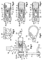
- FIG. 1 a clamp (1), a clamping bolt (2), a shaft (3), a lever (4), an eccentric head (5) of the lever (4), a stop (6) and a counterpart (7), wherein the clamp (1) engages around an element of the chassis of the vehicle, the clamping bolt (2) passes through the ends of the clamp (1), the shaft (3) is arranged at one end of the clamping bolt (2), the eccentric head (5) the lever (4) is rotatably mounted on the shaft (3), the stop (6) on the shaft (3) opposite end of the clamping bolt (2) is arranged and the counterpart (7) Orttsver Kunststofflich on the clamping bolt (2) between the Anschla g (6) and the eccentric head (5) is arranged.
- the essential components of the invention comprising a shaft (3) which is connected as an independent element fixed to the bolt (2), wherein the lever (4) is rotatably mounted on this shaft (3) and in its interior has an arrangement which is directed radially on the shaft (3), and on the basis of which at least one displaceable bolt (8), a displaceable lock body (9) which is actuated by a key (10), and a compression coil spring (11), wherein blocking means for blocking rotation of the lever (4) relative to the shaft (3) are provided, which is actuated by an actuation of the key (10) in conjunction with a displacement of the lever in the lever (4).
- provided arrangement can be activated, wherein the bolt (8) and the lock body (9) can occupy respective advanced and retracted operating positions, which the active or non-active state of this block comply with the regulations.
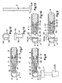
- the lever (4) has an opening (12) complementary to a locking end piece (15);
- the latch (8) has an aperture (13) provided with an edge (14) located at the rear end and transversely with respect to the feed of the bolt (8) towards the shaft (3), in which withdrawn and advanced operating positions of this bolt (8) this opening (13) can be circumscribed by a virtual cylinder, which is bounded by the opening of the lever (4), or the aperture with its trailing edge (14) can penetrate into this virtual cylinder said trailing edge (14) of the aperture (13) having a curved convex profile reciprocal of a constriction (16) in the locking end piece (15) installed at the end of an anti-theft loop cable (17) at its other end a loop (18) which can be traversed by the locking end piece (15).
- the compression spring (11) is arranged between the bolt (8) and the lock body (9) such that the spring (11) with one end permanently against a front pin (19) of the body (9), which slides during its operating stroke in a rear cavity (20) of the bolt (8) is arranged, at the same time the spring (11) is arranged with its other end in a recess (21) formed in the bottom of the rear cavity (20), wherein the Spring (11) can be fully pressed into this recess (21) and a state of maximum compression against the latch (8) and the lock body (9) assumes when they occupy their advanced operating positions, wherein the blocking means for blocking the rotational movement of the lever (4) relative to the shaft (3) in that the bolt (8) has a flat front edge (22) which is reciprocal to a flattening (23) formed on the circumference of the shaft (3), wherein in the provided pushed operation position of the bolt (8) this front edge (22) against the flattening (23) can be applied, wherein according to the advanced operating position of the lock body (9) in the inner wall of the lever (4) has
- the bolt (8) and the lock body (9) are fixedly connected to each other in an axial manner, and the bolt (8) is slidably inserted into a chamber (26) and tapers at its front part, whereby a shaft ( 27) which passes through the bottom of the chamber (26) and at its end a pin (28) which is inserted in the advanced position of the bolt (8) in a recess (29) of the shaft (3), wherein the helical compression spring (11) is disposed in the chamber (26) around the shaft (27) and between the end face of the bolt (8) and the bottom of the chamber (26).
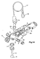
- the latch (8) and lock body (9) are interconnected as in the previous embodiment ( Figures 7 and 8), and because of the need for a locking pin (32) herein, an aperture (12) is provided ) is provided in the lever (4) into which this locking pin (32) of a theft protection loop cable (17) can be inserted, wherein the closing and opening by means of a ball (30) is achieved.
- the bolt (8) and the lock body (9) are connected to each other axially immovable, said bolt (8) slidably disposed in a chamber (26) and tapered at its front part, whereby a pin (27) is formed the tip of which may be applied against the ball (30) projecting partially out of the chamber (26) in a part which is reciprocal to a recess (31) located in the locking pin (32) opposite a plane side (32). 33) slidably penetrating the opening (12) and abutting against a flat portion (34) formed on the circumference of the shaft (3).
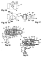
- the clamping bolt (2) is selectively screwed through the shaft (3) and has at its other end an extension forming a one-piece head (35) of a shape suitable for tooling a rotary actuator is inaccessible; one possible form for this is shown in FIG. 13, while another possible form is shown in FIG.
- a further preferred solution for the clamping bolt (2) consists in ( Figure 1) that the clamping bolt (2) by the shaft (3) is screwed in selectively changeable manner and at the other end of this clamping bolt (2) of the stop (6) is screwed into the shaft (3) and has an outer shape which is inaccessible to tools for a rotary operation, on its side, which protrudes from the clamp (1), this stop (6) comprises means for the application of such tools are suitable for a rotary actuator.
- the clamping bolt (2) can not be operated in the locked state of the lock.
- FIGs 14 to 19 a further embodiment of the seatpost lock for two-wheeled vehicles such as bicycles and motorcycles is shown, which corresponds to a general construction, comprising: a clamp (1), a clamping bolt (2), a shaft (3), a lever (4) an eccentric head (5) of the lever (4), a stop (6) and a counterpart (7), wherein the clamp (1) engages around an element of the frame of the vehicle, the clamping bolt (2) passes through the ends of the clamp (1) Shaft (3) in one end of the clamping bolt (2) is arranged, the eccentric head (5) of the lever (4) is rotatably mounted on the shaft (3), the stop (6) is arranged at the end of the clamping bolt, the shaft (3) is opposite, and the counterpart (7) is arranged so as to be displaceable on the clamping bolt (2) between the stop (6) and the concentric head (5), as shown in Figure 14.
- the blocking means for blocking rotation of the lever (4) relative to the shaft (3) is that the latch (8) has a front projection (36) extending transversely of the clamping bolt (Fig. 2) and parallel and arranged longitudinally with respect to the shaft (3).
- This front projection (26) has two flat sides, which with respect to the longitudinal working movement of the bolt (8) by an axially parallel side (37) and an end face (38) are formed, which are perpendicular to each other and at the end of the working stroke with respective Can be coupled, which form an angular recess in the shaft (3) and with respect to this working stroke a transverse wall (39) and a side wall (40), wherein the transverse wall (39) against the end face (36) and the side wall (40) against the axially parallel side (37) rests, while it is in front of this with respect to the rotational movement of the lever (4) in the sense of opening the lock in the open state of the castle.
- the lock body (9) can be actuated by means of a key (10), this possibility being shown in all drawings. This means that the open and closed state are each achieved by means of a suitable actuation of the key (10).
- a solution may be provided in which the displaceable lock body (9) forms the actual core of a combination lock with individual Einstellern, wherein in the lock secret corresponding position of this core forming lock body is freely displaceable while in any other position, these dials keep the core in the advanced state, which corresponds to the closed position of the lock.
- the dials of the combination lock take over the function of the key (10) in the above case.
Landscapes
- Engineering & Computer Science (AREA)
- Mechanical Engineering (AREA)
- Lock And Its Accessories (AREA)
Claims (14)
- Serrure pour support de selle pour les véhicules à deux roues comme, par exemple, les bicyclettes ou les motocyclettes, avec un collier de fixation (1), un boulon de fixation (2), un arbre (3), un levier (4), une tête excentrique (5) du levier (4), une butée (6) et une pièce antagonique (7), le collier de fixation (1) enveloppant un élément du cadre du véhicule, le boulon de fixation (2) traversant les extrémités du collier de fixation (1), l'arbre (3) étant disposé à une extrémité du boulon de fixation (2), la tête excentrique (5) du boulon de fixation (4) étant fixé à l'arbre (3) de façon à tourner, la butée (6) étant disposée à l'extrémité du boulon de fixation (2) en face de l'arbre (3) et la pièce antagonique (7) étant disposée de façon à pouvoir se déplacer sur le boulon de fixation (2) entre la butée (6) et la tête excentrique (5), l'arbre (3) étant accouplé, comme élément indépendant, fixement au boulon de fixation (2), le levier (4) étant fixé sur l'arbre (3) de façon à tourner et présentant à l'intérieur un dispositif qui est tourné vers l'arbre (3) dans une direction radiale et qui, en partant de celui-ci, se compose, au moins, d'un verrou déplaçable, d'un corps de serrure déplaçable (9), actionné au moyen d'une clé (10) ou d'un système de serrure comportant une combinaison de fermeture à rouages d'ajustement, et un ressort à vis de serrage (11) et des dispositifs de blocage étant fournis pour bloquer une rotation du levier (4) vis-à-vis de l'arbre (3), qui peuvent être actionnés en agissant sur la clé (10) ou les rouages d'ajustement, en même temps qu'un déplacement du dispositif à l'intérieur du levier (8) dans lequel le verrou (8) et le corps de serrure peuvent prendre les positions respectives de service en avant et en arrière, qui correspondent à l'état actif ou inactif des dispositifs de blocage.
- Serrure pour support de selle, conformément à la revendication 1, le levier (4) étant doté facultativement d'un orifice (12) qui est complémentaire d'une pièce finale de blocage (15).
- Serrure pour support de selle, conformément à la revendication 1 ou 2, le verrou (8) présentant une ouverture (13) dotée d'un rebord (14) qui est disposé à l'extrémité postérieure et dans le sens transversal par rapport au mouvement d'avance de service du verrou (8), dans la direction de l'arbre (3) et pouvant délimiter l'ouverture (3) par rapport aux positions de service vers l'avant et vers l'arrière de ce verrou, un cylindre virtuel, défini par l'orifice du levier (4) ou avec la possibilité pour ce rebord postérieur (14) de pénétrer dans le cylindre virtuel.
- Serrure pour support de selle, conformément à la revendication 3, le rebord (14) de l'ouverture (13) présentant un profil recourbé qui a une forme convexe, à l'opposite d'un rétrécissement (16) sur une pièce finale de blocage 5), qui est disposé à l'extrémité d'un câble à boucle de protection antivol (17), qui présente, à son autre extrémité, un tuyau flexible (18), qui peut ètre traversé par la pièce finale de blocage (15).
- Serrure pour support de selle, conformément aux revendications antérieures, le ressort de compression (11) étant monté entre le verrou (8) et le corps de la serrure (9), de telle sorte que le ressort (11) présente une extrémité adjacente de façon continue vis-à-vis d'un pivot avant (19) du corps de la serrure (9) qui, lors de son soulèvement de service, est introduit par glissement dans une cavité postérieure (20) du verrou (8), le ressort (11) étant disposé, en même temps, avec son autre extrémité, dans une dépression (21) formée à la base de la cavité postérieure (20), le ressort (11) pouvant être complètement reçu dans cette dépression (21) et adoptant un état de compression maximale, lorsque le verrou (8) et le corps de la serrure (9) adoptent leurs positions de service vers l'avant.
- Serrure pour support de selle, conformément aux revendications antérieures, les dispositifs de blocage consistant à bloquer une rotation du levier (4) par rapport à l'arbre (3) dans lequel le verrou (8) présente un rebord antérieur plat (22) à l'opposite d'un aplatissement (23), qui est prévu sur la circonférence de l'arbre (3) et ce rebord antérieur (22) étant en contact avec l'aplatissement (22) dans la position de service vers l'avant du verrou (8).
- Serrure pour support de selle conformément à l'une des revendications 1 à 4, le verrou (8) et le corps de la serrure (9) étant assemblés fixement entre eux dans une direction axiale, le verrou (8) étant monté par glissement dans une chambre (26) et se rétrécissant à son extrémité antérieure, formant ainsi une tige (27) qui traverse la base de la chambre (26) et qui, à son extrémité, présente un pivot (28) qui, dans la position vers l'avant du verrou (8), pénètre dans une encoche (29) de l'arbre (3), et le ressort à vis de serrage (11) étant disposé dans la chambre (26) autour de la tige (27) et entre le côté frontal du verrou (8) et la base de la chambre (26).
- Serrure pour support de selle conformément aux revendications 1 et 2, le verrou (8) et le corps de la serrure (9) étant assemblés fixement entre eux dans une direction axiale, le verrou (8) étant disposé par glissement dans uen chambre (26) et présentant, dans sa partie antérieure, un rétrécissement qui forme une tige (27) dont la pointe est en contact avec une bille (30) qui ressort en partie de la chambre (26) en un point à l'opposite d'une anse (31) qui se forme sur un pivot de blocage (32) en face d'un côté plat (33), qui pénètre dans l'ouverture (2) par glissement et qui est en contact avec une section plane (34) qui se forme sur la circonférence de l'arbre (3).
- Serrure pour support de selle conformément aux revendications antérieures, une encoche (24) étant pratiquée dans la paroi intérieure du levier (4) par rapport à la position de service vers l'avant du corps de la serrure (9), entaille (24) qui peut recevoir à l'intérieur une pièce de blocage (25) de la serrure, lorsque cette dernière est déplacée en tournant la clé (10) jusqu'à sa position de fermeture.
- Serrure pour support de selle conformément aux revendications antérieures, le boulon de fixation (2) étant vissé au moyen de l'arbre (3), de telle sorte qu'il peut ètre modifié de façon sélective, et étant élargi à son autre extrémité et formant une tête d'une pièce (5) qui a une forme qui le rend inacessible aux outils en vue de son actionnement moyennant rotation.
- Serrure pour support de selle conformément à l'une des revendications 1 à 9, le boulon de fixation (2) étant vissé au moyen de l'arbre (3), de telle sorte qu'il peut être modifié de façon sélective, et la butée (6) étant vissée à l'arbre (3) à l'autre extrémité de ce boulon de fixation (2), et présentant une forme extérieur qui le rend inaccessible aux outils pour son actionnement moyennant rotation, sur son côté qui ressort du collier de fixation (1), des dispositifs qui sont formés par la butée de ces outils.
- Serrure pour support de selle conformément à la revendication 1, les dispositifs de blocage consistant à bloquer la rotation du levier (4) vis-à-vis de l'arbre (3), où le verrou (8) présente une saillie antérieure (36), qui est transversale par rapport au boulon de fixation (2) et, en même temps, parallèle et longitudinale par rapport à l'arbre (3) où la saillie antérieure (36) présente deux côtés plats qui sont, par rapport au déplacement de service du verrou (8), d'une part, un côté parallèle à l'axe (37) et, de l'autre, un côté frontal (38), qui se trouvent à la verticale l'un par rapport à l'autre et qui, lors du déplacement de service, entrent en contact avec les parois respectives qui forment une échancrure en forme d'angle dans l'arbre (3), qui est formé, par rapport à ce déplacement, par une paroi transversale (39) et une paroi latérale (40), la paroi transversale (39) comprimant le côté frontal (38) et la paroi latérale (40) pouvant comprimer le côté parallèle à l'axe (37) et, devant celui-ci, par rapport au mouvement de rotation du levier (4) qui, en vue de l'ouverture de la serrure, est ajusté dans l'état débloqué de la serrure.
- Serrure pour support de selle, conformément à la revendication 12, le corps de la serrure déplaçable étant un corps de serrure pouvant être actionné au moyen d'une clé (10).
- Serrure pour support de selle, conformément à l'une des revendications 1 à 12, comportant un système de fermeture avec une combinaison à serrure ayant des rouages d'ajustement, le corps de la serrure (9), déplaçable par glissement, formant le noyau du système de fermeture à rouages d'ajustement, qui permettent un déplacement du noyau dans la position de rotation valable pour une ouverture, tandis que dans une autre position quelle qu'elle soit des rouages, ces rouages d'ajustement maintiennent le noyau dans un état vers l'avant, qui correspond à la position de fermeture de la serrure.
Applications Claiming Priority (4)
| Application Number | Priority Date | Filing Date | Title |
|---|---|---|---|
| ES200400178 | 2004-01-28 | ||
| ES200400178A ES2251858B1 (es) | 2004-01-28 | 2004-01-28 | "candado de tija para vehiculos de dos ruedas como bicicletas y ciclomotores". |
| ES200402491 | 2004-10-19 | ||
| ES200402491A ES2257184B1 (es) | 2004-01-28 | 2004-10-19 | "mejora en la patente de invencion p-200400178 por candado de tija para vehiculos de dos ruedas como bicicletas y ciclomotores". |
Publications (2)
| Publication Number | Publication Date |
|---|---|
| EP1559645A1 EP1559645A1 (fr) | 2005-08-03 |
| EP1559645B1 true EP1559645B1 (fr) | 2007-11-21 |
Family
ID=34655154
Family Applications (1)
| Application Number | Title | Priority Date | Filing Date |
|---|---|---|---|
| EP04031038A Expired - Lifetime EP1559645B1 (fr) | 2004-01-28 | 2004-12-30 | Dispositif de verrouillage du tube porte-selle de véhicules à deux roues comme des bicyclettes et des motocyclettes |
Country Status (2)
| Country | Link |
|---|---|
| EP (1) | EP1559645B1 (fr) |
| DE (1) | DE502004005554D1 (fr) |
Cited By (1)
| Publication number | Priority date | Publication date | Assignee | Title |
|---|---|---|---|---|
| EP4071035A1 (fr) | 2021-04-07 | 2022-10-12 | Ron Sklenar | Dispositif antivol pour motocycles |
Family Cites Families (4)
| Publication number | Priority date | Publication date | Assignee | Title |
|---|---|---|---|---|
| FR869214A (fr) * | 1941-01-14 | 1942-01-27 | Tige de selle antivol pour bicyclette | |
| IT8422920U1 (it) * | 1984-08-28 | 1986-02-28 | Carnielli & C Teodoro Spa | Dispositivo meccanico, applicabile su biciclette in genere, per il bloccaggio rapido di parti montate su tubo tondo metallico. |
| CA1268497A (fr) * | 1987-09-14 | 1990-05-01 | Robert J. Braun | Dispositif de surete pour selle de bicyclette |
| US5380061A (en) * | 1993-07-06 | 1995-01-10 | Pendleton; Robert C. | Bicycle seat security ring |
-
2004
- 2004-12-30 EP EP04031038A patent/EP1559645B1/fr not_active Expired - Lifetime
- 2004-12-30 DE DE502004005554T patent/DE502004005554D1/de not_active Expired - Fee Related
Cited By (3)
| Publication number | Priority date | Publication date | Assignee | Title |
|---|---|---|---|---|
| EP4071035A1 (fr) | 2021-04-07 | 2022-10-12 | Ron Sklenar | Dispositif antivol pour motocycles |
| DE102021001790A1 (de) | 2021-04-07 | 2022-10-13 | Christoph Hartmann | Diebstahlsicherungsystem für Motorräder mit hohler Steckachse an Vorder- und/oder Hinterrad |
| DE102021001790B4 (de) | 2021-04-07 | 2023-01-26 | Christoph Hartmann | Diebstahlsicherung für Motorräder |
Also Published As
| Publication number | Publication date |
|---|---|
| EP1559645A1 (fr) | 2005-08-03 |
| DE502004005554D1 (de) | 2008-01-03 |
Similar Documents
| Publication | Publication Date | Title |
|---|---|---|
| EP0374453B1 (fr) | Verrouillage pour volant de direction | |
| DE69806907T2 (de) | Verschlussvorrichtung für eine tür | |
| DE69229785T2 (de) | Motorradschloss | |
| DE4312458C2 (de) | Sperrvorrichtung für eine Scheibenbremse | |
| DE102007035116A1 (de) | Gelenkstabschloss | |
| DE10022373B4 (de) | Verriegelungs- und Betätigungseinheit für seitliche Auslegerverriegelung | |
| DE102009030031A1 (de) | Bügelschloss | |
| EP3135574B1 (fr) | Couplage | |
| DE2607609C3 (de) | Lenkschloß für Kraftfahrzeuge | |
| EP0541736B1 (fr) | Moyeu a serrage rapide pour bicyclettes | |
| DE202015106650U1 (de) | Schnellspann-Steckachse für Zweiräder | |
| EP1585880B1 (fr) | Systeme de fermeture pour fermer une porte ou un volet | |
| EP1559645B1 (fr) | Dispositif de verrouillage du tube porte-selle de véhicules à deux roues comme des bicyclettes et des motocyclettes | |
| DE2339919B2 (de) | Zylindrisches Einsteckschloß | |
| EP0844208B1 (fr) | Cric de véhicule | |
| EP3535463B1 (fr) | Unité de fermeture pour un véhicule automobile | |
| DE102013103898A1 (de) | Zuhaltevorrichtung für Schiebetüren und Verschlussvorrichtung für Schiebetüren | |
| DE19937128B4 (de) | Mitführbefestigung eines Zweiradschlosses an einem Zweirad | |
| DE10142278A1 (de) | Bügelschloss, insbesondere Fahrradbügelschloss | |
| EP1712458B1 (fr) | Unité réalisée avec un antivol de bicyclette | |
| DE69401294T2 (de) | Einrichtung zur Befestigung eines Schlosses in seinem Gehäuse | |
| DE19857266B4 (de) | Drehsperre | |
| DE3633392C2 (fr) | ||
| EP1473427B1 (fr) | Dispositif de blocage de sécurité | |
| DE29619084U1 (de) | Mechanische Sperrvorrichtung für Fahrräder |
Legal Events
| Date | Code | Title | Description |
|---|---|---|---|
| PUAI | Public reference made under article 153(3) epc to a published international application that has entered the european phase |
Free format text: ORIGINAL CODE: 0009012 |
|
| AK | Designated contracting states |
Kind code of ref document: A1 Designated state(s): AT BE BG CH CY CZ DE DK EE ES FI FR GB GR HU IE IS IT LI LT LU MC NL PL PT RO SE SI SK TR |
|
| AX | Request for extension of the european patent |
Extension state: AL BA HR LV MK YU |
|
| 17P | Request for examination filed |
Effective date: 20060203 |
|
| AKX | Designation fees paid |
Designated state(s): AT BE BG CH CY CZ DE DK EE ES FI FR GB GR HU IE IS IT LI LT LU MC NL PL PT RO SE SI SK TR |
|
| 17Q | First examination report despatched |
Effective date: 20060327 |
|
| GRAP | Despatch of communication of intention to grant a patent |
Free format text: ORIGINAL CODE: EPIDOSNIGR1 |
|
| GRAS | Grant fee paid |
Free format text: ORIGINAL CODE: EPIDOSNIGR3 |
|
| GRAA | (expected) grant |
Free format text: ORIGINAL CODE: 0009210 |
|
| AK | Designated contracting states |
Kind code of ref document: B1 Designated state(s): AT BE BG CH CY CZ DE DK EE ES FI FR GB GR HU IE IS IT LI LT LU MC NL PL PT RO SE SI SK TR |
|
| REG | Reference to a national code |
Ref country code: GB Ref legal event code: FG4D Free format text: NOT ENGLISH |
|
| REG | Reference to a national code |
Ref country code: IE Ref legal event code: FG4D Free format text: LANGUAGE OF EP DOCUMENT: GERMAN |
|
| REG | Reference to a national code |
Ref country code: CH Ref legal event code: EP |
|
| REF | Corresponds to: |
Ref document number: 502004005554 Country of ref document: DE Date of ref document: 20080103 Kind code of ref document: P |
|
| PG25 | Lapsed in a contracting state [announced via postgrant information from national office to epo] |
Ref country code: SE Free format text: LAPSE BECAUSE OF FAILURE TO SUBMIT A TRANSLATION OF THE DESCRIPTION OR TO PAY THE FEE WITHIN THE PRESCRIBED TIME-LIMIT Effective date: 20080221 Ref country code: ES Free format text: LAPSE BECAUSE OF FAILURE TO SUBMIT A TRANSLATION OF THE DESCRIPTION OR TO PAY THE FEE WITHIN THE PRESCRIBED TIME-LIMIT Effective date: 20080304 |
|
| PG25 | Lapsed in a contracting state [announced via postgrant information from national office to epo] |
Ref country code: PL Free format text: LAPSE BECAUSE OF FAILURE TO SUBMIT A TRANSLATION OF THE DESCRIPTION OR TO PAY THE FEE WITHIN THE PRESCRIBED TIME-LIMIT Effective date: 20071121 Ref country code: BG Free format text: LAPSE BECAUSE OF FAILURE TO SUBMIT A TRANSLATION OF THE DESCRIPTION OR TO PAY THE FEE WITHIN THE PRESCRIBED TIME-LIMIT Effective date: 20080221 Ref country code: FI Free format text: LAPSE BECAUSE OF FAILURE TO SUBMIT A TRANSLATION OF THE DESCRIPTION OR TO PAY THE FEE WITHIN THE PRESCRIBED TIME-LIMIT Effective date: 20071121 Ref country code: LT Free format text: LAPSE BECAUSE OF FAILURE TO SUBMIT A TRANSLATION OF THE DESCRIPTION OR TO PAY THE FEE WITHIN THE PRESCRIBED TIME-LIMIT Effective date: 20071121 Ref country code: IS Free format text: LAPSE BECAUSE OF FAILURE TO SUBMIT A TRANSLATION OF THE DESCRIPTION OR TO PAY THE FEE WITHIN THE PRESCRIBED TIME-LIMIT Effective date: 20080321 Ref country code: SI Free format text: LAPSE BECAUSE OF FAILURE TO SUBMIT A TRANSLATION OF THE DESCRIPTION OR TO PAY THE FEE WITHIN THE PRESCRIBED TIME-LIMIT Effective date: 20071121 |
|
| GBV | Gb: ep patent (uk) treated as always having been void in accordance with gb section 77(7)/1977 [no translation filed] | ||
| BERE | Be: lapsed |
Owner name: LUMA INDUSTRIAS, S.A. Effective date: 20071231 |
|
| PG25 | Lapsed in a contracting state [announced via postgrant information from national office to epo] |
Ref country code: CZ Free format text: LAPSE BECAUSE OF FAILURE TO SUBMIT A TRANSLATION OF THE DESCRIPTION OR TO PAY THE FEE WITHIN THE PRESCRIBED TIME-LIMIT Effective date: 20071121 Ref country code: MC Free format text: LAPSE BECAUSE OF NON-PAYMENT OF DUE FEES Effective date: 20071231 Ref country code: DK Free format text: LAPSE BECAUSE OF FAILURE TO SUBMIT A TRANSLATION OF THE DESCRIPTION OR TO PAY THE FEE WITHIN THE PRESCRIBED TIME-LIMIT Effective date: 20071121 |
|
| ET | Fr: translation filed | ||
| PG25 | Lapsed in a contracting state [announced via postgrant information from national office to epo] |
Ref country code: SK Free format text: LAPSE BECAUSE OF FAILURE TO SUBMIT A TRANSLATION OF THE DESCRIPTION OR TO PAY THE FEE WITHIN THE PRESCRIBED TIME-LIMIT Effective date: 20071121 Ref country code: RO Free format text: LAPSE BECAUSE OF FAILURE TO SUBMIT A TRANSLATION OF THE DESCRIPTION OR TO PAY THE FEE WITHIN THE PRESCRIBED TIME-LIMIT Effective date: 20071121 |
|
| PLBE | No opposition filed within time limit |
Free format text: ORIGINAL CODE: 0009261 |
|
| STAA | Information on the status of an ep patent application or granted ep patent |
Free format text: STATUS: NO OPPOSITION FILED WITHIN TIME LIMIT |
|
| PG25 | Lapsed in a contracting state [announced via postgrant information from national office to epo] |
Ref country code: PT Free format text: LAPSE BECAUSE OF FAILURE TO SUBMIT A TRANSLATION OF THE DESCRIPTION OR TO PAY THE FEE WITHIN THE PRESCRIBED TIME-LIMIT Effective date: 20080421 Ref country code: BE Free format text: LAPSE BECAUSE OF NON-PAYMENT OF DUE FEES Effective date: 20071231 |
|
| REG | Reference to a national code |
Ref country code: IE Ref legal event code: FD4D |
|
| 26N | No opposition filed |
Effective date: 20080822 |
|
| PG25 | Lapsed in a contracting state [announced via postgrant information from national office to epo] |
Ref country code: IE Free format text: LAPSE BECAUSE OF NON-PAYMENT OF DUE FEES Effective date: 20071231 |
|
| PG25 | Lapsed in a contracting state [announced via postgrant information from national office to epo] |
Ref country code: GB Free format text: LAPSE BECAUSE OF FAILURE TO SUBMIT A TRANSLATION OF THE DESCRIPTION OR TO PAY THE FEE WITHIN THE PRESCRIBED TIME-LIMIT Effective date: 20071121 |
|
| PG25 | Lapsed in a contracting state [announced via postgrant information from national office to epo] |
Ref country code: EE Free format text: LAPSE BECAUSE OF FAILURE TO SUBMIT A TRANSLATION OF THE DESCRIPTION OR TO PAY THE FEE WITHIN THE PRESCRIBED TIME-LIMIT Effective date: 20071121 Ref country code: GR Free format text: LAPSE BECAUSE OF FAILURE TO SUBMIT A TRANSLATION OF THE DESCRIPTION OR TO PAY THE FEE WITHIN THE PRESCRIBED TIME-LIMIT Effective date: 20080222 |
|
| PGFP | Annual fee paid to national office [announced via postgrant information from national office to epo] |
Ref country code: NL Payment date: 20081203 Year of fee payment: 5 |
|
| PGFP | Annual fee paid to national office [announced via postgrant information from national office to epo] |
Ref country code: IT Payment date: 20081222 Year of fee payment: 5 |
|
| PG25 | Lapsed in a contracting state [announced via postgrant information from national office to epo] |
Ref country code: AT Free format text: LAPSE BECAUSE OF NON-PAYMENT OF DUE FEES Effective date: 20071230 |
|
| PGFP | Annual fee paid to national office [announced via postgrant information from national office to epo] |
Ref country code: FR Payment date: 20081203 Year of fee payment: 5 |
|
| PGFP | Annual fee paid to national office [announced via postgrant information from national office to epo] |
Ref country code: DE Payment date: 20090302 Year of fee payment: 5 |
|
| PG25 | Lapsed in a contracting state [announced via postgrant information from national office to epo] |
Ref country code: CY Free format text: LAPSE BECAUSE OF FAILURE TO SUBMIT A TRANSLATION OF THE DESCRIPTION OR TO PAY THE FEE WITHIN THE PRESCRIBED TIME-LIMIT Effective date: 20071121 |
|
| REG | Reference to a national code |
Ref country code: CH Ref legal event code: PL |
|
| PG25 | Lapsed in a contracting state [announced via postgrant information from national office to epo] |
Ref country code: LU Free format text: LAPSE BECAUSE OF NON-PAYMENT OF DUE FEES Effective date: 20071230 |
|
| PG25 | Lapsed in a contracting state [announced via postgrant information from national office to epo] |
Ref country code: TR Free format text: LAPSE BECAUSE OF FAILURE TO SUBMIT A TRANSLATION OF THE DESCRIPTION OR TO PAY THE FEE WITHIN THE PRESCRIBED TIME-LIMIT Effective date: 20071121 Ref country code: HU Free format text: LAPSE BECAUSE OF FAILURE TO SUBMIT A TRANSLATION OF THE DESCRIPTION OR TO PAY THE FEE WITHIN THE PRESCRIBED TIME-LIMIT Effective date: 20080522 |
|
| PG25 | Lapsed in a contracting state [announced via postgrant information from national office to epo] |
Ref country code: LI Free format text: LAPSE BECAUSE OF NON-PAYMENT OF DUE FEES Effective date: 20081231 Ref country code: CH Free format text: LAPSE BECAUSE OF NON-PAYMENT OF DUE FEES Effective date: 20081231 |
|
| PG25 | Lapsed in a contracting state [announced via postgrant information from national office to epo] |
Ref country code: FR Free format text: LAPSE BECAUSE OF NON-PAYMENT OF DUE FEES Effective date: 20091231 |
|
| REG | Reference to a national code |
Ref country code: NL Ref legal event code: V1 Effective date: 20100701 |
|
| PG25 | Lapsed in a contracting state [announced via postgrant information from national office to epo] |
Ref country code: NL Free format text: LAPSE BECAUSE OF NON-PAYMENT OF DUE FEES Effective date: 20100701 |
|
| PG25 | Lapsed in a contracting state [announced via postgrant information from national office to epo] |
Ref country code: DE Free format text: LAPSE BECAUSE OF NON-PAYMENT OF DUE FEES Effective date: 20100701 |
|
| PG25 | Lapsed in a contracting state [announced via postgrant information from national office to epo] |
Ref country code: IT Free format text: LAPSE BECAUSE OF NON-PAYMENT OF DUE FEES Effective date: 20091230 |
|
| REG | Reference to a national code |
Ref country code: FR Ref legal event code: ST Effective date: 20110826 |