EP1559469A2 - Anlage und Verfahren zur Behandlung eines Kühlfluids in mechanischen Bearbeitungsanlagen - Google Patents
Anlage und Verfahren zur Behandlung eines Kühlfluids in mechanischen Bearbeitungsanlagen Download PDFInfo
- Publication number
- EP1559469A2 EP1559469A2 EP05075166A EP05075166A EP1559469A2 EP 1559469 A2 EP1559469 A2 EP 1559469A2 EP 05075166 A EP05075166 A EP 05075166A EP 05075166 A EP05075166 A EP 05075166A EP 1559469 A2 EP1559469 A2 EP 1559469A2
- Authority
- EP
- European Patent Office
- Prior art keywords
- plant according
- container
- base plate
- chamber
- mouth
- Prior art date
- Legal status (The legal status is an assumption and is not a legal conclusion. Google has not performed a legal analysis and makes no representation as to the accuracy of the status listed.)
- Granted
Links
- 238000012545 processing Methods 0.000 title claims abstract description 45
- 238000000034 method Methods 0.000 title claims abstract description 17
- 238000011084 recovery Methods 0.000 title description 9
- 239000012809 cooling fluid Substances 0.000 title description 3
- 239000007788 liquid Substances 0.000 claims abstract description 74
- 238000001914 filtration Methods 0.000 claims abstract description 44
- 239000012530 fluid Substances 0.000 claims abstract description 36
- 238000005406 washing Methods 0.000 claims abstract description 19
- 238000004140 cleaning Methods 0.000 claims abstract description 6
- 230000000737 periodic effect Effects 0.000 claims abstract description 4
- 238000005192 partition Methods 0.000 claims abstract 19
- 238000007789 sealing Methods 0.000 claims description 40
- 230000006835 compression Effects 0.000 claims description 25
- 238000007906 compression Methods 0.000 claims description 25
- 239000007787 solid Substances 0.000 claims description 24
- 238000013022 venting Methods 0.000 claims description 17
- 238000007790 scraping Methods 0.000 claims description 13
- 239000000463 material Substances 0.000 claims description 8
- 230000008569 process Effects 0.000 claims description 7
- 230000007246 mechanism Effects 0.000 claims description 6
- 230000001681 protective effect Effects 0.000 claims description 6
- 230000000630 rising effect Effects 0.000 claims description 6
- 238000007664 blowing Methods 0.000 claims description 5
- 238000002347 injection Methods 0.000 claims description 5
- 239000007924 injection Substances 0.000 claims description 5
- 238000005096 rolling process Methods 0.000 claims description 5
- 239000004744 fabric Substances 0.000 claims description 4
- 239000000314 lubricant Substances 0.000 claims description 4
- 239000004677 Nylon Substances 0.000 claims description 3
- 229920001778 nylon Polymers 0.000 claims description 3
- 229910000831 Steel Inorganic materials 0.000 claims description 2
- 230000004888 barrier function Effects 0.000 claims description 2
- 230000001112 coagulating effect Effects 0.000 claims description 2
- 238000007599 discharging Methods 0.000 claims description 2
- 230000001105 regulatory effect Effects 0.000 claims description 2
- 230000002441 reversible effect Effects 0.000 claims description 2
- 239000010959 steel Substances 0.000 claims description 2
- 241000196324 Embryophyta Species 0.000 description 25
- XLYOFNOQVPJJNP-UHFFFAOYSA-N water Substances O XLYOFNOQVPJJNP-UHFFFAOYSA-N 0.000 description 8
- 238000009826 distribution Methods 0.000 description 7
- 230000036961 partial effect Effects 0.000 description 7
- 239000002245 particle Substances 0.000 description 5
- 238000000926 separation method Methods 0.000 description 5
- 230000009471 action Effects 0.000 description 4
- 238000007726 management method Methods 0.000 description 4
- 239000002184 metal Substances 0.000 description 4
- 229910052751 metal Inorganic materials 0.000 description 4
- 230000008901 benefit Effects 0.000 description 3
- 239000011148 porous material Substances 0.000 description 3
- 239000003643 water by type Substances 0.000 description 3
- PXHVJJICTQNCMI-UHFFFAOYSA-N Nickel Chemical compound [Ni] PXHVJJICTQNCMI-UHFFFAOYSA-N 0.000 description 2
- 239000000839 emulsion Substances 0.000 description 2
- 230000006870 function Effects 0.000 description 2
- 239000000843 powder Substances 0.000 description 2
- 238000004064 recycling Methods 0.000 description 2
- 239000011343 solid material Substances 0.000 description 2
- 238000005507 spraying Methods 0.000 description 2
- 238000003466 welding Methods 0.000 description 2
- 241000219104 Cucurbitaceae Species 0.000 description 1
- 230000004913 activation Effects 0.000 description 1
- 230000002730 additional effect Effects 0.000 description 1
- 230000015572 biosynthetic process Effects 0.000 description 1
- 230000000903 blocking effect Effects 0.000 description 1
- 239000003795 chemical substances by application Substances 0.000 description 1
- 238000004891 communication Methods 0.000 description 1
- 230000001276 controlling effect Effects 0.000 description 1
- 239000000110 cooling liquid Substances 0.000 description 1
- 230000003247 decreasing effect Effects 0.000 description 1
- 238000001514 detection method Methods 0.000 description 1
- 230000000916 dilatatory effect Effects 0.000 description 1
- 238000006073 displacement reaction Methods 0.000 description 1
- 230000009977 dual effect Effects 0.000 description 1
- 230000000694 effects Effects 0.000 description 1
- 230000008030 elimination Effects 0.000 description 1
- 238000003379 elimination reaction Methods 0.000 description 1
- 238000005516 engineering process Methods 0.000 description 1
- 238000000605 extraction Methods 0.000 description 1
- 230000008595 infiltration Effects 0.000 description 1
- 238000001764 infiltration Methods 0.000 description 1
- 238000003780 insertion Methods 0.000 description 1
- 230000037431 insertion Effects 0.000 description 1
- 238000005304 joining Methods 0.000 description 1
- 230000000670 limiting effect Effects 0.000 description 1
- 238000012986 modification Methods 0.000 description 1
- 230000004048 modification Effects 0.000 description 1
- 229910052759 nickel Inorganic materials 0.000 description 1
- 230000000149 penetrating effect Effects 0.000 description 1
- 238000003825 pressing Methods 0.000 description 1
- 239000002994 raw material Substances 0.000 description 1
- 230000008439 repair process Effects 0.000 description 1
- 238000007493 shaping process Methods 0.000 description 1
- 238000007711 solidification Methods 0.000 description 1
- 230000008023 solidification Effects 0.000 description 1
- 239000000243 solution Substances 0.000 description 1
- 125000006850 spacer group Chemical group 0.000 description 1
- 235000020354 squash Nutrition 0.000 description 1
- 238000013519 translation Methods 0.000 description 1
- 238000011144 upstream manufacturing Methods 0.000 description 1
Images










Classifications
-
- B—PERFORMING OPERATIONS; TRANSPORTING
- B01—PHYSICAL OR CHEMICAL PROCESSES OR APPARATUS IN GENERAL
- B01D—SEPARATION
- B01D29/00—Filters with filtering elements stationary during filtration, e.g. pressure or suction filters, not covered by groups B01D24/00 - B01D27/00; Filtering elements therefor
- B01D29/11—Filters with filtering elements stationary during filtration, e.g. pressure or suction filters, not covered by groups B01D24/00 - B01D27/00; Filtering elements therefor with bag, cage, hose, tube, sleeve or like filtering elements
- B01D29/111—Making filtering elements
-
- B—PERFORMING OPERATIONS; TRANSPORTING
- B01—PHYSICAL OR CHEMICAL PROCESSES OR APPARATUS IN GENERAL
- B01D—SEPARATION
- B01D29/00—Filters with filtering elements stationary during filtration, e.g. pressure or suction filters, not covered by groups B01D24/00 - B01D27/00; Filtering elements therefor
- B01D29/11—Filters with filtering elements stationary during filtration, e.g. pressure or suction filters, not covered by groups B01D24/00 - B01D27/00; Filtering elements therefor with bag, cage, hose, tube, sleeve or like filtering elements
- B01D29/13—Supported filter elements
- B01D29/23—Supported filter elements arranged for outward flow filtration
-
- B—PERFORMING OPERATIONS; TRANSPORTING
- B01—PHYSICAL OR CHEMICAL PROCESSES OR APPARATUS IN GENERAL
- B01D—SEPARATION
- B01D29/00—Filters with filtering elements stationary during filtration, e.g. pressure or suction filters, not covered by groups B01D24/00 - B01D27/00; Filtering elements therefor
- B01D29/62—Regenerating the filter material in the filter
- B01D29/64—Regenerating the filter material in the filter by scrapers, brushes, nozzles, or the like, acting on the cake side of the filtering element
- B01D29/6438—Regenerating the filter material in the filter by scrapers, brushes, nozzles, or the like, acting on the cake side of the filtering element nozzles
-
- B—PERFORMING OPERATIONS; TRANSPORTING
- B01—PHYSICAL OR CHEMICAL PROCESSES OR APPARATUS IN GENERAL
- B01D—SEPARATION
- B01D29/00—Filters with filtering elements stationary during filtration, e.g. pressure or suction filters, not covered by groups B01D24/00 - B01D27/00; Filtering elements therefor
- B01D29/62—Regenerating the filter material in the filter
- B01D29/66—Regenerating the filter material in the filter by flushing, e.g. counter-current air-bumps
- B01D29/661—Regenerating the filter material in the filter by flushing, e.g. counter-current air-bumps by using gas-bumps
-
- B—PERFORMING OPERATIONS; TRANSPORTING
- B01—PHYSICAL OR CHEMICAL PROCESSES OR APPARATUS IN GENERAL
- B01D—SEPARATION
- B01D29/00—Filters with filtering elements stationary during filtration, e.g. pressure or suction filters, not covered by groups B01D24/00 - B01D27/00; Filtering elements therefor
- B01D29/62—Regenerating the filter material in the filter
- B01D29/70—Regenerating the filter material in the filter by forces created by movement of the filter element
- B01D29/72—Regenerating the filter material in the filter by forces created by movement of the filter element involving vibrations
-
- B—PERFORMING OPERATIONS; TRANSPORTING
- B01—PHYSICAL OR CHEMICAL PROCESSES OR APPARATUS IN GENERAL
- B01D—SEPARATION
- B01D2201/00—Details relating to filtering apparatus
- B01D2201/04—Supports for the filtering elements
- B01D2201/0415—Details of supporting structures
-
- B—PERFORMING OPERATIONS; TRANSPORTING
- B01—PHYSICAL OR CHEMICAL PROCESSES OR APPARATUS IN GENERAL
- B01D—SEPARATION
- B01D2201/00—Details relating to filtering apparatus
- B01D2201/29—Filter cartridge constructions
- B01D2201/291—End caps
Definitions
- the present invention refers to the treatment of recovery waters used, sometimes suitably additived, as a cooling fluid in mechanical processing plants for chip removal.
- the treatment is not limited to recovery fluid of mechanical processing, but is also carried out to recover residual liquids of other types of processing.
- a first reason is of the ecological type, and requires that the muds that form in said waters be separated to allow recycling or else discharge thereof into the environment.
- a third reason is the perfect and complete separation of the material filtered from the treated liquid.
- recovery liquids of mechanical processing they consist of water, water/oil emulsions or even just oil.
- the recovery of the liquids is particularly important in fine processing, for example lapping, of metal surfaces coated with precious and valuable materials like for example nickel.
- Plants suitable for treating residual water of mechanical processing comprising filtering means, in series or in parallel, consisting of a toroidal filtering cartridge arranged in a cylindrical box that is divided by the cartridge into two concentric parts, the central one of which can also communicate with the outside through an opening foreseen on the bottom of the box for the evacuation of mud.
- the liquid to be filtered is generally fed inside (to the centre) of the cartridge, crosses it and is evacuated outside of the box.
- the solid material contained in the liquid remains lodged inside the cartridge where it forms a layer that must be periodically removed, since as it increases in thickness it progressively clogs up the cartridge.
- the removal is carried out through a periodic washing in equicurrent, in other words spraying the layer of mud through nozzles and collecting the material that detaches through suitable means.
- the periodic cleaning system of the cartridge takes place at fairly long time intervals, which depend upon the amount of mud contained in the liquid, and the size of the particles of which it is made up.
- the washing action is generally controlled by detecting the pressure inside the cartridge, which increases as the clogging increases.
- the size of the chip particles is in the order of between 0.1 and 7.0 microns, and the mud not only tends to clog up the filtering cartridge very quickly, but the washing operation carried out in the conventional way is not sufficient to restore the characteristics of the cartridge.
- the clogging of the cartridge indeed, does not depend exclusively upon the thickness of the layer of mud that forms on the filtering surface, but also upon the partial insertion of the particles to be separated in the pores of the filtering surface.
- the purpose of the present invention is to provide a method and plant for managing the filters in systems for treating the leftover liquids of mechanical processing that does not have the aforementioned drawbacks.
- a further purpose of the present invention is that of making a separating apparatus for muds from mechanical processing that is able to work continuously without requiring that the machines for mechanical processing connected to it be stopped.
- Yet another purpose of the present invention is that of making a separating apparatus for muds from mechanical processing that is compact and also easy to connect to filtering apparatuses, decanting tanks and machines for mechanical processing that are already known and operating.
- Another technical task of the present invention is that of providing a double suction submerged pump structure suitable for recycling the liquids in the above mentioned filtering plant
- the further purpose of the present invention is that of making a double suction submerged pump structure with vertical axis in which the axial thrusts on the drive shaft are balanced and which has a pump structure that can be applied particularly to tanks for collecting liquids containing muds from mechanical processing.
- Another important purpose of the present invention is that of making a pneumatic valve suitable for the above mentioned plant, that wears down less from the passage of metallic muds from mechanical processing with respect to known valves, and that can easily be managed without electrical or electronic management and control means.
- an important purpose of the present invention is that of making a separating and recovery device of liquids from muds processed by the above mentioned plants that is able to make the solid part recovered from such muds disposable.
- the filters have the exit chamber of the treated liquid arranged in communication, through suitable piloted valves, with a pressurised air tank.
- the pressure is preferably between 3 and 7 bar, and the valves are commanded to open repeatedly at predetermined time intervals for very brief periods.
- the periods during which the valves open and close are between 0.1 and 2.0 seconds, whereas the intervals between one period and the next are between 3 and 60 seconds.
- the action of the air impulses converts into liquid impulses that make the film of water in contact with the layer of solid material vibrate, keeping it disintegrated and preventing it from accumulating to such a degree as to clog up the filter.
- the state of vibration caused in the film of water in contact with said layer also prevents the solid particles from inserting into the pores of the filter itself.
- the apparatus comprises a separating and recovery device of liquids from muds from mechanical processing, comprising a tubular container closed at the top by a cover and at the bottom by an openable filtering and discharge base plate hinged to it through articulation means, said container being fed through an inlet mouth open on its high part, said base plate being equipped with a lower outlet channel for the liquids extracted from the muds, and with a filtering element suitable for holding the solid part of said muds at the lower end section of said container, said device having means for raising the pressure inside said container, suitable for compressing said muds towards said filtering element, air venting means, also on the high part of the container, and moving means suitable for opening/closing said base plate.
- the apparatus according to the invention can comprise also an improved filter of the type consisting of two concentric tubular bodies with reticular structure, a sieve layer being present between said two tubular bodies suitable for holding chips from mechanical processing, the end sections of said two tubular bodies, with sieve layer interposed, being sealed by a sealing edge, said sealing edges consisting of a sealing ring equipped with a slit in which said end sections reversibly insert.
- a double suction submerged pump structure is has a vertical axis, and comprises, in a protective containment casing, a rotation shaft on which at least a pair of opposite interfacing impellers is fitted inside a chamber, for said impellers, for conveying the fluid towards a delivery, said shaft being rotatable on rotational sliding means and actuated at the top end by a motor, said shaft also having fluidic sealing means associated with it arranged between said motor and said chamber for the impellers.
- Said submerged pump structure has, below said pair of rotating suction elements, a hollow tang, integral with said casing, defining a seat for the bottom end of said shaft, between said shaft and said tang being arranged said rotational sliding means and corresponding further fluidic sealing means positioned between said rotational sliding means and said chamber.
- the invention comprises a distribution device of liquids consisting of a box-shaped body equipped, at the top part, with an inlet mouth open on a tank for liquids, and below such an inlet mouth, with a discharge mouth for the liquid contained therein, said inlet mouth having a pneumatic valve according to the invention, suitable for regulating its opening and closing.
- Said device comprises air compression means for closing said inlet mouth through said pneumatic valve and for blowing pressurised air into said top part of said box-shaped body, to make said liquid flow inside said box-shaped body from said discharge mouth.
- Said pneumatic valve comprises a frame equipped with a first and second opening, one for inlet and one for outlet, for the passage of fluids, inside said frame being arranged an air chamber that, inflating, is suitable for pushing a shutter against said first through opening, said air chamber being arranged sandwiched between compression means, suitable for disengaging said shutter from said first through opening in the absence of pressure inside said air chamber.
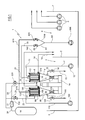
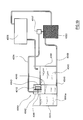
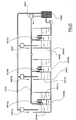
- FIG. 1 a plant is illustrated, wholly indicated with reference numeral 1, which is operatively connected with a mechanical processing station with chip removal, like for example a CCN type centre.
- processing with chip removal is carried out in the presence of a suitable cooling fluid, usually water possibly additived with products and suitable agents, a water/oil emulsion or just oil.
- a suitable cooling fluid usually water possibly additived with products and suitable agents, a water/oil emulsion or just oil.
- the chips can be quite coarse or relatively very fine as specified in the preamble.
- the plant shown comprises a tank 2 that is divided into a collection basin 3 (on the left in the Fig.) of the dirty fluid coming from said processing, and a collection basin 4 of the clean, i.e. filtered, fluid (on the right in the Fig.).
- At least one recirculation pump (in the Fig. three in number), suitable for supplying the clean fluid to said station, or another suitable place, and a pump 600 that is intended to send clean fluid to the washing device 10, 100 arranged in the inner chamber of the filtering group of the plant 1 through a delivery duct 60 that separates into two branches 61, 610 individually intercepted by a valve 62, 620, draw from the basin 4.
- said filtering group comprises two side-by-side identical cylindrical chambers with vertical axes that are set above the basin 3.
- Each individual chamber comprises an outer casing 6 and 66, respectively, which is closed at the top by a cover 7, 77 and at the bottom communicates with a funnel-shaped body 8, 88.
- said inner zone houses a washing device 10, 100, also of the known type, which comprises a series of vertical spraying arms.
- Said arms are individually equipped with a plurality of nozzles facing towards the inner surface of the cartridge 9, 99 and are connected to a common central collector that is supplied with clean fluid by the respective branch 61, 610 of the common delivery duct 60.
- said supply of clean fluid takes place through the cover 7, 77 through the washing device where the delivery duct 11, 110 of a pump 12, 120 that draws from the basin 3 also flows.
- 77 pressure detection means 13, 130 are also installed that are connected with the general control and adjustment system of the plant.
- a discharge duct 14, 140 of the filtered fluid that pours into the basin 4 derives from the lower band of the casing 6, 66 and is intercepted by a pneumatic double effect valve 214, 215.
- a normal discharge duct 15, 150 of the washing fluid derives that is intercepted by a valve 16, 160 and pours into the basin 3, and an equally normal openable discharge mouth of the washing liquid 17, 170 with which a collector 18 of the recovered muds is associated underneath is associated with the lower end of the same funnel 8, 88.
- the plant 1 is provided with a compressed air source, in the present case consisting of a tank 19.
- said two branches 22, 23 pour into the casings 6 and 66, respectively, so as to supply said compressed air to the outer zones thereof where the filtered fluid passes.
- piloted valve 21 is structured so as to open repeatedly during the course of processing at predetermined time intervals and for very brief time periods.
- Said opening time period is about 0.1-2 minutes seconds, and the interval between two consecutive periods is in the order of 3-60 seconds.
- the piloted valve 21 is obviously placed under the control of the general control and adjustment system of the plant 1. It can be of any known type suitable for the purpose, for example model PVLB101618W2 of American company PARKER has proven suitable.
- said general control and adjustment system also comprises memory means in which the desired maximum value that the pressure can reach in the inner zone of the casing 6, 66 during filtration is stored, a value that indicates the maximum degree of clogging of the cartridge 9, 99.
- the described plant 1 operates substantially as follows, supposing that both of the chambers of the filtration group are used (in the contrary case, for example use of just the right chamber, the following will be deactivated: the delivery branch 610 of the clean fluid; the delivery pump 110 of the dirty fluid; and the delivery branch 23 of the pressurised air).
- the delivery branch 600 of the clean fluid is deactivated; the pumps 12 and 120 send the dirty fluid inside the inner zone of the casings 6 and 66; the filtered fluid crosses the cartridges 9 and 99 and discharges into the basin 4 through the ducts 14 and 140; and the valves 16, 160 and the mouths 17, 170 are closed.
- piloted valve 21 opens and closes at least twice for periods of 0.5-2 seconds at intervals of 3-60 seconds.
- the first of which is that of dispersing the layer of mud that has deposited on the inner surface of the cartridges 9, 99, which once broken collects in the funnel 8, 88 below, and the second consists of preventing at least part of the finest particles present in said mud from clogging up the interstices or pores of the cartridges 9, 99.
- the washing step of the cartridges 9, 99 can be deferred in time, thus reducing the idle times of the plant 1.
- the corresponding delivery pump 12 or 120 of the dirty fluid is stopped, and at the same time the respective delivery branch 61 or 610 of the clean fluid is activated, the valve 16 or 160 for discharging the washing fluid into the basin 3 is opened, and the mud is discharged into the container 18 through the mouth 17 or 170.
- the vibrating state of the cartridges 9, 99 caused by the compressed air impulses is preferably also maintained during the washing step.
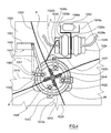
- a separating apparatus for muds is wholly indicated with reference numeral 1010.
- Such an apparatus 1010 consists of a box-shaped body 1011 inside which there is a decanting tank 1012.
- Such a decanting tank 1012 is supplied by two entry mouths 1013, from which flows mud from metal processing coming from a further upstream decanting tank, or from a previous filter device such as this disclosed in Fig. 1.
- the decanting tank 1012 has an outlet mouth 1014 for the liquid 1050 at least partially separated from the mainly solid residue 1051, which tends to deposit on the bottom 1015 of the tank 1012.
- the outlet mouth 1014 opens at a greater height from the ground than the entry mouths 1013, the latter being connected to the funnels 8, 88 of Fig. 1.
- the pick-up means 1016 comprise a rotation device 1018 for four scraping blades 1019.
- Each blade 1019 is connected through a pair of paddles 1020 to the rotation device 1018.
- the paddles 1020 are of the leaf spring type, and slightly arched with convexity facing in the direction of advance.
- Such a configuration of the paddles 1020 prevents the blades 1019 from jamming blocking the entire apparatus should they have to move too great an amount of residue 1051 or in the case in which they intercept other types of obstacles on their path.
- the leaf spring configuration thus allows the paddles 1020 to bend in the opposite direction to the advancing direction, and thus allows possible obstacles in which the scraping blades 1019 can get caught to be passed.
- the blades 1019 indeed, in their rotary motion about the axis of the rotation device 1018, scrape the bottom 1015 of the tank 1012, and lift the mainly solid residue 1051 deposited there up to said discharge means 1017.
- the decanting tank 1012 has a substantially arc of circumference shaped vertical longitudinal section 1015a.
- Such an arc 1015a which in the embodiment described here is greater than 180°, defines the path that the blades 1019 make the residue 1051 lifted from the bottom 1015 follow and simultaneously acts as an edge that holds such raised residue 1051 on the blades 1019.
- the rotation device 1018 is given by a rotation shaft 1021 to which the paddles 1020 are integrally fixed, a gear wheel 1022 with saw teeth 22a being in turn fixed to the shaft 1021.
- the paddles 1020 are locked with threaded elements 1044 to plate-shaped supports 1045 welded radially and arranged longitudinally on the rotation shaft 1021.
- the gear wheel 1022 is actuated, or rather rotated, by a ratchet gear 1023 the movement of which is managed by a first device 1024 for generating alternative motion.
- the ratchet gear 1023 also comprises an anti-return sprag 1025 for said gear wheel 1022.
- the first device for generating alternative motion 1024 is made up of two pneumatic valves 1026, a first valve 1026a and a second valve 1026b, respectively.
- a thrusting pawl 1027 for the gear wheel 1022 is sandwiched between the two pneumatic valves 1026a and 1026b.
- Each of the pneumatic valves 1026 is fixed by the non-engaged end with the thrusting pawl 1027, respectively the first end 1028a of the first valve 1026a and second end 1028b of the second valve 1026b, to a wall 1029 of the box-shaped body 1011.
- the discharge means 1017 consist of a removal element 1030 moved by a second device for generating alternative motion 1031 and projecting, in extracted position, from a discharge edge 1032 of the decanting tank 1012.
- Such a discharge edge 1032 is arranged above the free surface of the liquid 1050.
- the removal element 1030 is in the form of an upturned drawer 1033.
- Such an upturned drawer 1033 in extracted position, intercepts a scraping blade 1019 rising from the bottom 1015 of the tank 1012, and, sliding on such a blade 1019 towards a withdrawn position, removes the mainly solid residue 51 present on the adjacent blade 1019.
- the upturned drawer 1033 drags the residue 1051 from the scraping blade 1019 situated at the discharge edge 1032, up to a discharge passage 1034 defined on the box-shaped body 1011 near to the discharge edge 1032 itself.
- Such a passage 1034 opens onto a removable container 1035 for collecting and disposing the mainly solid residue 1051.
- the removal element 10030 or rather the upturned drawer 1033, is arranged in withdrawn position with its inner face 1036 at a distance no less than the radius of the arc of circle section of the tank 1012 away from the axis of the rotation shaft 1021 of the blades 1019.
- the second device for generating alternative motion 1031 is given by two further pneumatic valves 1037, between which the upturned drawer 1033 is sandwiched, through a rod 1038 that supports it.
- Each of such further pneumatic valves 1037 is fixed by the end 1039 not engaged with the rod 1038 to the wall 1029 of the box-shaped body 1011.
- the second device for generating alternative motion 1031 is controlled by a timing mechanism 1040 that coordinates its alternate translating movement with the rotary movement of the scraping blades 1019.
- the timing mechanism 1040 comprises a valve 1041 for controlling the pressure inside the second device for generating alternative motion 1031.
- Such a control valve 1041 is fixed to a wall 1029 of the box-shaped body 1011 and is actuated through an automatic return leverage 1042, pushed by a cam 1043 rotating integrally with the blades 1019.
- the timing mechanism 1040 comprises as many cams 1043 as there are scraping blades 1019.
- Such cams 1043 are fixed substantially radially to the gear wheel 1022 through further threaded elements 1046 slotted in corresponding slots 1047 open on the cams 1043.
- the operation of the apparatus 1010 according to the invention is the following.
- the pneumatic valves 1026 are alternatively filled with pressurised air coming, through the ducts 1048, from a pump (not illustrated, for the sake of simplicity).
- the inflation of the first valve 1026a causes the translation of the thrusting pawl 1027, which thrusts the gear wheel 1022 into rotation, through the saw tooth 1022b on which it is rested.
- the gear wheel 1022, and with it the scraping blades 1019, carries out a part rotation until the anti-return sprag 1025 clicks onto the saw tooth next to the one in which it was engaged before the first valve 1026a inflated.
- the first valve 1026a inflating, as well as translating the pawl 1027, moves a first switching appendix 1049 in the same direction, which acts on a pressure switch 1052.
- the pressure switch 1052 deviates the compressed air from the first valve 1026a to the second valve 1026b, which by inflating leads to the simultaneous deflation of the first valve 1026a, to the withdrawal of the pawl 1027 to ride over an underlying tooth 1022c of the gear wheel 1022 and, through a second switching appendix 1049b, to the subsequent further activation of the switch 1052.
- the blades 1019 scrape the bottom 10015 of the tank 1012 and lift part of the residue 1051 towards the discharge edge 1032.
- the cams 1043 also rotate integrally with the gear wheel 10032.
- cams 1043 and paddles 1020 The relative position of cams 1043 and paddles 1020 is such that a cam 1043 acts on the leverage 1042 so that the upturned drawer 1033 is arranged in extracted position shortly before the passage of the corresponding blade 1019 loaded with residue 1051.
- control valve 1041 which, switched through the leverage 1042, deviates the pressurised air to the first further pneumatic valve 1037a.
- control valve 1041 deviates the compressed air flow from the first 1037a to the second further pneumatic valve 1037b, which, inflating, drags the drawer 1033 towards the discharge passage 1034, in withdrawn position.
- the drawer 1033 in extracted position, intercepts the blade 1019, which rises from the bottom 1015 and, closing into withdrawn position, removes the at least partially solid residue 1051 carried by the blade 1019.
- the residue 1051 removed by the blade 1019 is dragged by the drawer 1033 beyond the edge 1032 up to the passage 1034, through which the residue 1051 falls into the container 1035 below.
- the rotary movement of the apparatus 1010 is therefore in successive clicks, defined by the number of teeth 1022a of the gear wheel 1022 and by the action of the first device for generating alternative motion 1024.
- the second device for generating alternative motion 1031 which controls the removal element 1030, is actuated at predetermined intervals in relation to a certain number of clicks completed by the ratchet gear 1023.
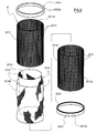
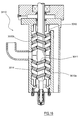
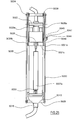
- the improved filter according to the invention is wholly indicated with reference numeral 2010.
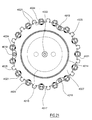
- Such an improved filter 2010 consists of a first and second tubular body, 2011 and 2012 respectively in the Fig.s.
- Such two tubular bodies 2011 and 2012 both have a reticular structure, having a plurality of square windows 2013.
- the two tubular bodies 2011 and 2012 are concentric and the inner surface 2011a of the first tubular body 2011 is adjacent to the outer surface 2012a of the second tubular body 2012.
- the first and second tubular body 2011 and 2012 are arranged with respect to each other so that the windows 2013a of the first correspond to the windows 2013b of the second.
- such a sieve layer 2014 is made up of a first inner layer 2014a and a second outer layer 2014b.
- first and second layers 2014a, 2014b are angled to surround the end sections 2015 and 2017, upper and lower respectively, of the first tubular body 2011.
- the end sections, both the upper ones, indicated with 2015 for the first tubular body 2011 and with 2016 for the second tubular body 2012, and the lower ones, 2017 for the first tubular body 2011 and 2018 for the second tubular body 2012, are each sealed by a sealing edge, which pinches the lips 2030 on the end sections of the first tubular body 2011.
- the upper sealing edge is indicated by number 2020 and the lower sealing edge is indicated by number 2021.
- the improved filter 2010 is characterised in that each of the sealing edges 20020 and 2021 consists of a sealing ring 2020a and 2021a, respectively.
- Each ring is equipped with a slit 2022 and 2023 respectively, in which the end sections 2015 and 2016 in the slit 2022 of the upper ring 2020a and 2017 and 2018 in the slit 2023 of the lower ring 2021a insert.
- the two tubular bodies 2011 and 2012, in the present embodiment, are cylindrical.
- the two layers 2014a and 2014b that make up the sieve layer 2014 are advantageously made from nylon.
- Such a sieve layer 2014 in a variant embodiment of an improved filter according to the INVENTION 2010, can have at least an outer layer of the two layers of which it consists made from steel mesh.
- Each sealing ring 2020a and 2021a is made from rubber.
- the second tubular body is obtained by shaping a substantially rectangular portion of metallic mesh into a cylinder, without however welding together the two interfacing sides 2140 and 2141.
- the side 2141 has at least two slits 2131, arranged symmetrically, suitable for receiving in reversible engagement a threaded element 2133 slotted into a corresponding window 2113b present close to the opposite side, in this case 2140.
- the slit 2131 in the present example, is open on the outside of the side 2141.
- Such a threaded element 2133 has a substantially flat head 2133a, a body with a square section 2133b, shaped to engage without rotating in a window 2113b, and a threaded shank 2133c that inserts in the slit 2131 and onto which a lock nut 2132 screws.
- the tightening of the nut 2132 locks the two sides 2140 and 2141 in position one on top of the other.
- such a second tubular body 2112 ensures that it tends to expand once inserted inside the first tubular body, thus perfectly adhering to the sieve layer 2014 and advantageously pressing it against the first tubular body.
- a second tubular body 20112 in the variant embodiment just described allows a second embodiment of the sieve layer 2014 to be used (not illustrated for the sake of simplicity).
- Such a second embodiment is given by a sieve layer 2014 not stitched longitudinally.
- Such an unstitched sieve layer 2014 is obtained from a substantially rectangular portion of fabric, unwoven fabric, metallic mesh or similar (or combinations of such materials) arranged adjacent to the inner surface 11a inside the first tubular body 11 with its unwoven longitudinal lips overlapping.
- the second tubular body 2112 is inserted in the variant embodiment described above.
- Such a second tubular body 2112 not yet locked by the clamping of the nut 2132 to the threaded element 2133, dilating and increasing its diameter, compresses the layer 2014 against the first tubular body 2011.
- the layer 2014 although not stitched longitudinally, is thus immobilised between the two tubular bodies.
- the lips 2030 of the layer 2014 wind around the end sections 2015 and 2017, upper and lower respectively, of the first tubular body 2011.
- a double suction submerged pump structure with vertical axis according to the invention is disclosed in the Fig. 14 to 16.
- a rotation shaft on which at least a pair of opposite interfacing impellers is fitted inside a chamber, for said impellers, for conveying the fluid towards a delivery, said shaft being rotatable on rotational sliding means and actuated at the top end by a motor, said shaft also having fluidic sealing means associated with it arranged between said motor and said chamber for the impellers.
- Said submerged pump structure has, below said pair of rotating suction elements, a hollow tang, integral with said casing, defining a seat for the bottom end of said shaft, between said shaft and said tang being arranged said rotational sliding means and corresponding further fluidic sealing means positioned between said rotational sliding means and said chamber.
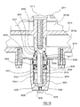
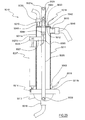
- the double suction submerged pump structure in a first embodiment thereof is wholly indicated with reference numeral 3010.
- Such a structure 3010 comprises, in a protective containment casing, a rotation shaft 3012 on which a pair of opposite interfacing suction impellers 3013 is fitted inside a chamber 3014, for such impellers 3013, for conveying the fluid towards a delivery 3015.
- the shaft 12 actuated at the top end 3016 by a motor (not illustrated for the sake of simplicity), is rotatable on rotational sliding means 3018.
- First fluidic sealing means 3038 are associated with such a shaft, arranged between the motor and the chamber 3014.
- Such a submerged pump structure 3010 has, below the pair of suction impellers 3013, a hollow tang defining a seat 3020 for the bottom end 3019 of the shaft 3012.
- Such a hollow tang is integral with the casing 3011.
- Such second fluidic sealing means 3017 are positioned between the rotational sliding means 3018 and the chamber 3014.
- the rotational sliding means 3018 are given by a first lower rolling bearing 3021 and by a second upper rolling bearing 3022, which surround the bottom end 3019 of the rotation shaft 3012.
- Such first and second bearings 3021, 3022 are kept in mutual position by a spacer 3023 placed between said bearings 3021 and 3022 and by anti-slip elements arranged below the first bearing 3021 and above the second bearing 3022.
- the rotational sliding means 3018 also comprise an oil-blocking ring 3024 suitable for preventing leaking from the seat 3020 inside the hollow tang towards the conveying chamber 3014 of the lubricant in which the bearings 3021 and 3022 are immersed.
- the sealing means 3017 are given by a pair of sealing rings interfacing in the axial direction.
- a first sealing ring 3025 is inserted in the seat 3020 above the oil-blocking ring 3024 and a second sealing ring 3026 surrounds the rotation shaft 3012.
- the second ring 3026 is pressed against the first ring 3025 by elastic means 3027 also integral with the rotation shaft 3012.
- Such elastic means 3027 consist of a spring, placed between said second sealing ring 3026 and a first abutment shoulder 3031 of said rotation shaft 3012.
- the first abutment shoulder 31 forms part of a small support shaft 3040, which forms the bottom end 3019 of the shaft 3012, and is only ready to work following the assembly of the impellers 3013 on the shaft 3012.
- the first and second sealing rings 3025, 3026 are made from widia.
- the seat 3020 is made from a cup-shaped element 3028 fixed below the conveying chamber 3014 and open towards it.
- the cup-shaped element 3028 is advantageously removable from the chamber 3014, to allow the replacement or repair of the sealing rings 3025 and 3026, of the bearings 3021 and 3022, or of any other component that is accessible by removing such a cup-shaped element 3028.
- a variant of the INVENTION (not illustrated) has a cup-shaped element 3028 that forms a single body with the conveying chamber 3014.
- the cup-shaped element 3028 has, at its base 3029, an injection hole 3030 for a lubricant for the rotational sliding means 3018.
- the anti-slip elements consist of a second shoulder 3032, inside the cup-shaped element 3028, on which the first lower bearing 3021 abuts, and an elastic ring 3033 housed in its own hollow countershape 3034 to block the second upper bearing 3022 at the top.
- the submerged pump structure 3010 described here, as stated, has double suction.
- a first suction mouth 3035 is open, downwards, on said chamber 3014.
- a second suction mouth 3036 opens on the side of the protective containment casing 3011, and above the conveying chamber 3014.
- the second mouth 3036 has a drawing tube 3037 that allows such a second mouth 3036 to suck up from a height substantially equal to that of the first mouth 3035.
- the submerged pump structure 3010 also comprises first fluidic sealing means 3038, which guard the motor from the liquid sucked up, and are arranged on the shaft 3012 near to the motor itself.
- the first fluidic sealing means 3038 consist of a pair of oil-blocking rings 3038a and 3038b respectively, that are interfacing and pressed against the shaft 3012 by a volume of pressurised oil 3039 defined by the two oil-blocking rings 3038a and 3038b.
- the interfacing and opposite impellers 3013 consist of two bladed impellers 3013a and 3013b, respectively.
- the chamber 3014 is given by a volute.
- the impellers 3113 consist of two interfacing and opposite Archimedean screws 3113a and 3113b
- the chamber 3114 of the impellers 3113 is given by a tubular body the internal diameter of which substantially coincides with the external diameter of the auger 3141 of the Archimedean screws 3113a and 3113b.
- the second fluidic sealing means 3017 are in a depression zone, from which the liquid with the metal chips is sucked up by the impellers 3013 or 3113.
- the arrangement of the sealing means in a depression zone prevents the metal chips from penetrating between the two widia sealing rings 3025 and 3026, prolonging their lifetime and therefore optimally preserving the rotational sliding means 3018 from infiltration.
- a double suction submerged pump structure with vertical axis has been provided that can particularly be applied to tanks for collecting liquids containing muds from mechanical processing.
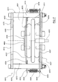
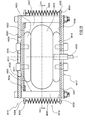
- a pneumatic valve according to the invention in a first embodiment, is wholly indicated with reference numeral 4010.
- Such a valve 4010 comprises a frame 4011, equipped with a first and second opening 4012, 4013 respectively, one for inlet and one for outlet, for the passage of fluids, generally liquids containing muds from mechanical processing.
- an air chamber 4014 is arranged that, inflating, is suitable for pushing a shutter 4015 against the first through opening 4012.
- the air chamber 4014 is arranged sandwiched between compression means 4016, suitable for disengaging the shutter 4015 from the first through opening 4012 in the absence of pressure inside the air chamber 4014 itself.
- the frame 4011 is made up of a first plate 4017, to which the air chamber 4014 is fixed through a first fastening ring 4018 coaxial to it.
- connection uprights 4019 for the first plate 4017 with a second plate 4020 extend, equally spaced apart.
- the compression means 4016 are given by a plurality of springs 4021 arranged between a compression plate 4022 of the air chamber 4014 and the first plate 4017, to move the compression plate 4022 in the direction of inflation of the air chamber 4014.
- the compression plate 4022 is locked to a second fastening ring 4023 coaxial and integral with the air chamber 4014 at the opposite side with respect to the first ring 4018.
- the springs 4021 are traction springs and are hooked by their annular ends 4024 to corresponding first projections 4025, integral with the first plate 4017, and symmetrical to corresponding second projections 4026 integral with the compression plate 4022.
- the first projections 4025 extend radially from a disc 4027 locked between the first plate 4017 with which it is integral and the first fastening ring 4018.
- the second projections 4026 extend radially from the compression plate 4022.
- the shutter 4015 is defined by a thickness of rubber 4028 with a section no smaller than the section of said first through opening 4012.
- Such a thickness of rubber 4028 is integral with the face 4029 of the compression plate 4022 facing towards the first through opening 4012.
- the first through opening 4012 is given by a circular through hole 4030 obtained on the second plate 4020.
- the second through opening 4013 consists of the open areas 4031 defined by two uprights 4019 consecutive with the inner surfaces 4032 of the first and second plates 4017, 4020.
- the first plate 4017 has a connection nozzle 4033 for the compressed air ducts 4034 for inflating the air chamber 4014.
- Such a valve 4010 is closed if pressurised air is blown into the air chamber 4014.
- the blowing of air causes the air chamber 4014 to inflate, which, lifting up, overcomes the force of the springs 4021 and pushes the thickness of rubber 4028 to block the first opening 4012.
- first through opening 4012 is opened and it is made possible for liquid to pass between them and then through the open areas 4031 that define the second opening 4013.
- the flow of liquid through the first and second openings 4012, 4013 is of course allowed in both directions.
- a valve 4010 according to the invention can be controlled through compressed air, and does not have electrical or electronic components that can easily be damaged, above all if constantly inserted in a wet area like a decanting tank or similar.
- a pneumatic valve according to the invention in a second embodiment is indicated in Fig. 22 with reference numeral 4110.
- Such a valve 4110 is characterised in that the compression means 4116, suitable for disengaging the shutter 4115 from the first through opening 4112, are given by a pneumatic piston 4170, fixed to the first plate 4117 and with its stem 4171 fixed to the shutter 4115 for moving the latter.
- the piston 4170 is arranged with its stem 4171 substantially coaxial to the air chamber 4114, to act in traction on the shutter 4115 connected to it and in compression on said air chamber 4114.
- the cylinder 4172 of the piston 4170 indeed, defines a thrusting chamber 4170a and a traction chamber 4170b.
- the stem 4171 and the cylinder 4172 of the piston 4170 from which it extends advantageously have passages 4173 for a pressurised air flow coming from the piston 4170 and aimed towards the inside of the air chamber 4114.
- Such passages 4173 consist of a first through hole 4174 on the cylinder 4172, from which cylinder 4172 extends a substantially tubular stem 4171a coaxially to the first hole 4174.
- Such a tubular stem 4171a has second connection holes 4175 of the thrusting chamber 4170a of the piston 4170 with the air chamber 4114.
- the passages 4173 for the pressurised air allow a further function to be obtained from the piston, in addition to that of disengaging the shutter 4115 from the first opening 4112, which is that of increasing the closing force of the shutter 4115 on such a first opening 4112 itself.
- the shutter 4115 is pushed both through the action of the air chamber 4114, inflated through the passages 4173, and through the additional action of the stem 4171, pushed by the cylinder 4172 in turn subjected to the same pressure that allows the air chamber 4114 to be inflated.
- a distribution device of liquids indicated in Fig. 19 with reference numeral 4040.
- Such a device 4040 consists of a box-shaped body 4041, equipped in its top part 4042 with an inlet mouth 4043 open on a tank 4044 for liquids 4045, which, in the present example, should be considered as containing muds from metallic processing.
- the tank 4044 is thus for decanting such liquids 4045 containing metallic muds.
- a pneumatic valve 4010 as described above is applied to the inlet mouth 4043.
- Such a valve 4010 regulates the opening/closing of the inlet mouth 4043.
- the device 4040 comprises compression means 4047 of the air for closing the inlet mouth 4043 through the pneumatic valve 4010.
- Such compression means 4047 are also suitable for blowing pressurised air into the upper part 4042 of the box-shaped body 4041.
- the air blown into the upper part 4042 of the box-shaped body 4041 makes the liquid 4045a inside the box-shaped body 4041 flow out from the discharge mouth 4046.
- the second plate 4017 of the valve 4010 consists of a wall 4048 of the box-shaped body 4041.
- the pneumatic valve 4010 is arranged inside the box-shaped body 4041.
- valve 4010 is arranged outside the box-shaped body 4041.
- the valve 4010 By actuating the air compression means 4047, the valve 4010 is closed and the liquid 4045a containing metallic muds flows out from inside the box-shaped body 4041, through a duct 4049, towards a filtering plant 4050.
- the liquid 45a enters into the device 4040 by overflowing from the decanting tank 4044.
- Such a liquid 4045a comes from the liquid with muds 4045 discharged from the mechanical processing machines, generically indicated with reference numerals 4051, 4051a and so on, and it is already summarily purified through the decanting to which it is subjected in the tank 4044.
- the filter 4050 thus receives the liquid 4045a that contains less metallic muds with respect to the liquid with muds 4045.
- a distribution device of liquids containing muds from metallic processing comprising at least one pneumatic valve as described in the present invention, and therefore able to be controlled without the use of electrical management and control means, has been provided.
- a separating and recovery device of liquids from muds from mechanical processing according to the invention is wholly indicated with reference numeral 5010.
- Such a device 5010 consists of a tubular container 5011 closed at the top by a cover 5012 and at the bottom by an openable filtering and discharge base plate 5013.
- the base plate 5013 is hinged to the container 5011 through articulation means 5014 described better later on.
- the container 5011 is fed through an inlet mouth 5015 open on the high part 5011a of the container 5011 itself.
- the muds which in the Fig.s are indicated with reference numeral 5070, are picked up from a mud-collection tank.
- the base plate 5013 is equipped with a lower outlet channel 5016 for the liquids 5072 extracted from the muds 5070, and with a filtering element 5017 suitable for holding the solid part 5071 of the muds 5070 at the lower end section 5011b of the container 5011.
- the device 5010 has means for raising the pressure 5018 inside the container 5011.
- Air venting means 5019 are also present, again on the high part 5011a of the container 50011, which allow air (and possible overloads of liquid) to escape from inside the container 5011 when the muds 5070 are introduced into it.
- the device 5010 also comprises moving means 5020 for opening/closing the base plate 5013.
- the moving means 5020 of the base plate 5013 consist of an interfixed or first type of lever 5021, the pivot 5022 of which, with a horizontal axis, is supported by supports 5023 rising from the upper cover 5012.
- the lever 5021 is firmly connected at a first end 5021a with a first turning pair 5024 to a tie rod 5025 for opening/closing the base plate 5013, and at the second end 5021b, with a second turning pair 5026, to actuation means 5027 in turn hinged to the container 5011.
- the tie rod 5025 is rotatably fixed to the base plate 5013 with a third turning pair 5029.
- the lever 5021 consists of a pair of first rods 5028 arranged symmetrically on two opposite sides of the container 5011.
- Each of such first rods 5028 is substantially L-shaped, with the vertical portion 5028a in closing position for the base plate 5013, substantially interfacing with the tie rod 5025.
- the second ends 5021b of the first rods 5028 are rigidly fixed through a crosspiece 5021c, which carries the connection turning pair 5026 with the actuation means 5027.
- tie rod 5025 is given by two second rectilinear rods 5030, hinged as described each to the adjacent first rod 5028.
- such a plane perpendicular to the base plate 5013 is symmetrical with the container 5011.
- the vector of the pressure force indeed, lies on the perpendicular plane defined previously, containing the rotation axes of the pivot 5022 and of the first and third turning pairs 5024, 5029.
- Such a structure of moving means 5020 advantageously implies greater safety of use of the device 5010.
- Such supports 5023 are height-adjustable.
- the adjustment of the supports 5023 allows the clamping force of the base plate 5013 to be varied according to requirements.
- said articulation means 5014 for the base plate 5013 consist of a pin 5031 arranged to roto-translate in a guide 5032 integral with the container 5011.
- the pin 5031 with its axis parallel to the rotation axes of the pivot 50022 and of the first and third turning pairs 5024, 5029, is able to follow the vertical displacement set by the height-adjustment of the supports 50023.
- the guide 5032 is in the form of a profile with rectangular section, welded on the back of the container 5011, substantially at the hinging 5033 of the actuation means 5027.
- Such actuation means 5027 are in the form of a double acting pneumatic actuation cylinder 5027a.
- the filtering element 5017 is given by a sieve 5034 with a surface such as to cover at least the entire lower end section 5011b of the container 5011.
- Such a sieve 5034 made from nylon or metallic mesh, is integral with the base plate 5013.
- the sieve 5034 is pressed by the base plate 5013 in closed position against an annular gasket 5035 with which the lower edge 5036 of the container 5011 is equipped.
- the base plate 5013 has a collection basin 5037 for the liquids 5072 coming from the compression of the muds 5070.
- the basin 5037 is open on the outlet channel 5016, which takes the liquids 5072 to the circulation tanks.
- the base plate 5013 has a dividing wall 5038 equipped with a plurality of first discharge holes 5039 arranged at the sieve 5034.
- Such first holes 5039 are distributed inside a ring 5040 of second discharge holes 5041 arranged at the annular gasket 5035, such a ring 5040 being integral with the dividing wall 5038 and therefore with the basin 5037.
- the sieve 5034 is locked above the first holes 5039 inside the ring 5040.
- the means for raising the pressure 5018 consist of a plurality of first air-injectors 5042, only one of which is illustrated as an example in the Fig.s.
- Such first injectors 5042 are arranged to blow air inside the container 5011 from the cover 5012 of the container 5011 itself.
- the injection of air into the container 5011 causes the pressure to rise, which is necessary to push the muds 5070 onto the sieve 5034 of the closed base plate 5013.
- the means for raising the pressure 5018 comprise at least one second air injector 5043 close to the lower end section 5011b of the container 5011.
- Such second injectors 5043 remix the layer made up of the solid part 5071 of the muds 5070, a layer that is in the process of solidifying on the sieve 5034.
- Such a layer indeed, tends to still hold liquid 5072, and during solidification on such a layer preferential passages for the air coming from the first injectors 5042 form, which, having run-off channels, no longer carries out the liquid-solid separation operation for which it is injected.
- the second injectors 5043 are activated, which remix the solidifying layer, preventing the formation of run-off channels for the air and improving the separation of the liquids 5072 from the muds 5070, and therefore at the same time the cleaning of the solid part 5071.
- the device 5010 has a safety locking device 5044 suitable for reversibly locking the lever 5021 to the tie rod 5025 in closed position of the base plate 5013.
- Such a locking device 5044 is pneumatically actuated, and is in the form of a pin 5045, the housing 5047 of which is fixed on one of the second rods 5030.
- the pin 5045 is pushed/withdrawn in a countershaped hole 5046 on the adjacent vertical portion 5028a of the first rod 5028.
- the inlet mouth 5015 has opening/closing means 5048 suitable for adjusting the amount of muds 5070 poured in the container 5011.
- the venting means 5017 consist of a venting mouth 5049, open on the cover 5012 and are equipped with second opening/closing means 5050.
- Such first opening/closing means 5048 for the inlet mouth 5015, just like the second opening/closing means 5050 for the venting mouth 5049 are given by a pneumatically actuated valve.
- FIG. 28a to 28f A process for separating the solid part from the liquids of muds from mechanical processing, through a device 5010 as described up to now, is illustrated in Fig. 28a to 28f and can be schematised as follows:
- the muds start to become denser on the sieve 5034, forming a layer that itself becomes a further, finer filter for the muds above.
- the metallic chip powder that remains in the liquid, indeed, to a large extent comes from the initial step of the compression of the muds, in which the deposits on the sieve are scarce and the finest metallic chip powder is substantially free to slip through the sieve.
- the second air injectors 5043 are activated and it proceeds as follows:
- a tile 5051 can be left inside the container 5011 for further liquid separation and recovery cycles, also as an auxiliary filter for the sieve 5034.
- the tile 5051 When it has reached a certain maximum thickness, or else after a certain number of cycles, the tile 5051 is disposed of through the opening of the base plate 5013.
- the recovered liquid 5072 is sent back to the circulation tanks that serve the machine tools.
- Such a process can advantageously be timed, giving each step a predetermined length.
- Such a device 5010 according to the invention allows over 90% of the cooling liquid contained in the muds 5070 to be recovered, compared to 60-70% in known apparatuses and plants.
Landscapes
- Chemical & Material Sciences (AREA)
- Chemical Kinetics & Catalysis (AREA)
- Filtration Of Liquid (AREA)
- Fertilizers (AREA)
- Apparatuses For Bulk Treatment Of Fruits And Vegetables And Apparatuses For Preparing Feeds (AREA)
- Filtering Materials (AREA)
Applications Claiming Priority (10)
| Application Number | Priority Date | Filing Date | Title |
|---|---|---|---|
| ITPD20040027 | 2004-01-30 | ||
| ITPD20040027 ITPD20040027A1 (it) | 2004-01-30 | 2004-01-30 | Filtro perfezionato particolarmente per impianti di trattamento per fanghi da lavorazioni meccaniche |
| ITPD20040028 ITPD20040028A1 (it) | 2004-01-30 | 2004-01-30 | Dispositivo di separazione e recupero di liquidi da fanghi di lavorazioni meccaniche |
| ITPD20040028 | 2004-01-30 | ||
| ITRE20040012 | 2004-02-27 | ||
| ITRE20040012 ITRE20040012A1 (it) | 2004-02-27 | 2004-02-27 | Metodo ed impianto per il trattamento del fluido refrigerante di recupero negli impianti di lavorazione meccanica |
| ITPD20040072 ITPD20040072A1 (it) | 2004-03-22 | 2004-03-22 | Attrezzatura di separazione per fanghi da lavorazioni mecaniche |
| ITPD20040072 | 2004-03-22 | ||
| ITPD20040123 ITPD20040123A1 (it) | 2004-05-14 | 2004-05-14 | Struttura di pompa sommersa a doppia aspirazione ad asse verticale |
| ITPD20040123 | 2004-05-14 |
Publications (3)
| Publication Number | Publication Date |
|---|---|
| EP1559469A2 true EP1559469A2 (de) | 2005-08-03 |
| EP1559469A3 EP1559469A3 (de) | 2005-10-19 |
| EP1559469B1 EP1559469B1 (de) | 2011-10-12 |
Family
ID=34658193
Family Applications (1)
| Application Number | Title | Priority Date | Filing Date |
|---|---|---|---|
| EP05075166A Expired - Lifetime EP1559469B1 (de) | 2004-01-30 | 2005-01-21 | Anlage und Verfahren zur Behandlung eines Kühlfluids in mechanischen Bearbeitungsanlagen |
Country Status (3)
| Country | Link |
|---|---|
| US (1) | US8361313B2 (de) |
| EP (1) | EP1559469B1 (de) |
| AT (1) | ATE528054T1 (de) |
Cited By (4)
| Publication number | Priority date | Publication date | Assignee | Title |
|---|---|---|---|---|
| US20050167373A1 (en) * | 2004-01-30 | 2005-08-04 | P.M.P.O. S.R.L. | Plant and method for the treatment of the recovery cooling fluid in mechanical processing plants |
| US7662296B2 (en) * | 2006-09-28 | 2010-02-16 | P.M.P.O. S.R.L. | Filtering and compacting device for solid particles suspended and contained in fluids, such as slurry from mechanical operations |
| RU2417114C1 (ru) * | 2009-11-30 | 2011-04-27 | Эдуард Федорович Соловьев | Система очистки жидкости |
| CN110075584A (zh) * | 2019-05-07 | 2019-08-02 | 哈尔滨三幸水处理设备制造有限公司 | 一种机械过滤器的过滤清洗方法 |
Families Citing this family (19)
| Publication number | Priority date | Publication date | Assignee | Title |
|---|---|---|---|---|
| US20050263450A1 (en) * | 2004-05-28 | 2005-12-01 | Mcgrew Henry E Jr | Removable submersible pump filter |
| US9149743B2 (en) | 2007-10-04 | 2015-10-06 | Michael K. Conwell | Apparatus for dewatering solids-laden liquids |
| US8070960B2 (en) * | 2007-10-04 | 2011-12-06 | Conwell Michael K | Method of dewatering solids laden liquids utilizing a reusable filter element |
| US8951411B2 (en) * | 2008-04-02 | 2015-02-10 | Eitan Sharir | Apparatus for waste-water filtration |
| DE102008047427A1 (de) * | 2008-09-15 | 2010-04-15 | Bähr, Albert, Dipl.-Ing. | Verfahren und Vorrichtung zur Fest-Flüssig-Trennung von Stoffgemischen und Suspensionen |
| US9556874B2 (en) * | 2009-06-09 | 2017-01-31 | Pentair Flow Technologies, Llc | Method of controlling a pump and motor |
| US20110017230A1 (en) * | 2009-07-27 | 2011-01-27 | Memc Electronic Materials, Inc. | Method and System for Processing Abrasive Slurry |
| US20110084029A1 (en) * | 2009-10-08 | 2011-04-14 | Dominick O' Reilly | Waste treatment system |
| US20110089097A1 (en) * | 2009-10-19 | 2011-04-21 | O'reilly Dominick | Attachment and system for dewatering material |
| US20110094395A1 (en) * | 2009-10-26 | 2011-04-28 | O'reilly Dominick | Method and attachment for dewatering logs |
| US10112136B2 (en) * | 2012-02-03 | 2018-10-30 | Enviro-Fab Llc | Fluid lubricant and material shavings recapture system for a cutting operation |
| JP5667230B2 (ja) * | 2013-03-15 | 2015-02-12 | ファナック株式会社 | 工作機械の切削液管理装置 |
| US20180280840A1 (en) * | 2017-03-29 | 2018-10-04 | Larry Baxter | Method and Device for Separating Solids and Liquids using a Modified Pump |
| US12179299B2 (en) * | 2018-08-07 | 2024-12-31 | Illinois Tool Works Inc. | Machine tool with recirculating coolant filtration system |
| CN109876538A (zh) * | 2019-04-01 | 2019-06-14 | 郑州碧兴环保科技有限公司 | 一种机械自动化反冲洗污水处理装置 |
| US11456681B2 (en) * | 2020-01-08 | 2022-09-27 | Encite Llc | Micro electrostatic actuated pneumatic driven motor |
| SE544566C2 (en) * | 2020-01-31 | 2022-07-19 | Hydria Water Ab | A separation device and method to separate contaminants from contaminated water |
| CN114272658B (zh) * | 2021-12-31 | 2023-07-28 | 青岛品品好粮油集团有限公司 | 海藻过滤浓香花生油加工设备及工艺 |
| JP2024043122A (ja) * | 2022-09-16 | 2024-03-29 | キオクシア株式会社 | 端材回収装置 |
Citations (3)
| Publication number | Priority date | Publication date | Assignee | Title |
|---|---|---|---|---|
| FI103325B (fi) | 1997-05-20 | 1999-06-15 | Timo Pekka Antero Taehkioe | Kirkastussuodatin ja menetelmä sen regeneroimiseksi |
| EP1306118A1 (de) | 2001-10-24 | 2003-05-02 | Boll & Kirch Filterbau GmbH | Verfahren zur Reinigung eines Filters für Flüssigkeiten und System zur Durchführung des Verfahrens |
| DE10226463A1 (de) | 2002-06-13 | 2004-01-08 | Faudi Filtersysteme Gmbh | Filtereinrichtung und Verfahren zur Abreinigung von feinporigen Filtermitteln |
Family Cites Families (92)
| Publication number | Priority date | Publication date | Assignee | Title |
|---|---|---|---|---|
| US406161A (en) * | 1889-07-02 | Jean ceabanel | ||
| US1946663A (en) * | 1930-11-05 | 1934-02-13 | Simplicity Eng Co | Dewatering device |
| US2075207A (en) * | 1933-06-20 | 1937-03-30 | Lee H Kessler | Sand dewatering apparatus |
| US2267086A (en) * | 1937-07-22 | 1941-12-23 | William J Donohue | Filtering method and apparatus |
| US2167236A (en) * | 1938-06-17 | 1939-07-25 | Dracco Corp | Filtering apparatus |
| US2731151A (en) * | 1951-05-05 | 1956-01-17 | Turbine Equipment Company | System for handling metal chips and extracting oil therefrom |
| US3115458A (en) * | 1960-05-11 | 1963-12-24 | Michael J Bebech | Apparatus for filtering liquids |
| US3055290A (en) * | 1960-05-19 | 1962-09-25 | Arvan Products Inc | Filter system |
| US3161591A (en) * | 1961-03-02 | 1964-12-15 | Ronningen Petter Company | Filtering apparatus for liquid materials |
| GB1226742A (de) * | 1967-04-06 | 1971-03-31 | ||
| US3422958A (en) * | 1967-09-26 | 1969-01-21 | Ajem Lab Inc | Precoat filter |
| US3482700A (en) * | 1968-06-17 | 1969-12-09 | Michael J Bebech | Multiple filter element cleaning means |
| US3796316A (en) * | 1972-07-07 | 1974-03-12 | A Matz | Water filtering apparatus |
| US4136035A (en) * | 1977-07-26 | 1979-01-23 | Bogomolov Boris N | Apparatus for dehydration of continuously fed flow of suspension |
| DE2752906A1 (de) * | 1977-11-26 | 1979-05-31 | Holstein & Kappert Maschf | Verfahren und vorrichtung zum reinigen von innerhalb eines kesselfilters angeordneten spaltfilterelementen |
| DE2828976C2 (de) * | 1978-07-01 | 1983-06-01 | Bergwerksverband Gmbh, 4300 Essen | Anschwemmkerzenfilter-Vorrichtung für Trockenaustrag und Verfahren zur Reinigung der Vorrichtung |
| US4289630A (en) * | 1979-12-10 | 1981-09-15 | Industrial Filter & Pump Mfg. Co. | Filter cake removal method and apparatus |
| DE3113624A1 (de) * | 1980-04-22 | 1982-04-08 | British Sidac Ltd., Watford, Hertfordshire | "rueckspuelbare filtriervorrichtung" |
| US4387633A (en) * | 1981-02-06 | 1983-06-14 | James Ballantyne | Sludge processing system |
| US4394262A (en) * | 1982-08-06 | 1983-07-19 | Zurn Industries, Inc. | System for minimizing backwash water usage on self-cleaning strainers |
| US4552669A (en) * | 1983-04-18 | 1985-11-12 | Mott Metallurgical Corporation | Pneumatic hydro-pulse filter system and method of operation |
| JPS61126009A (ja) * | 1984-11-21 | 1986-06-13 | Yasuo Arai | 化粧料の充填固化方法および充填固化装置 |
| CS249589B1 (en) * | 1985-09-26 | 1987-04-16 | Karel Gabriel | Device for components' cleaning by means of near ultrasonic field especially with cylindrical filter elements |
| DE3631399A1 (de) * | 1986-09-16 | 1988-03-17 | Boll & Kirch Filter | Filter, insbesondere anschwemmfilter |
| US4895647A (en) * | 1987-08-12 | 1990-01-23 | Syst Corp | Filtering apparatus |
| US4836922A (en) * | 1987-08-12 | 1989-06-06 | Delaware Capital Formation, Inc. | Vibrating filter apparatus |
| US5032293A (en) * | 1989-05-23 | 1991-07-16 | Buckman Laboratories International, Inc. | Basket filter assembly with inclined nozzle |
| US5106487A (en) * | 1989-07-26 | 1992-04-21 | Inter-Source Recovery Systems, Inc. | Parts separator device for separating heavy materials from chips and lubricants |
| US5084176A (en) * | 1990-03-09 | 1992-01-28 | Delaware Capital Formation, Inc. | Vibrating filter |
| IT1248282B (it) * | 1991-02-21 | 1995-01-05 | Graziano Lagreca | Unita' di disidratazione di fanghi, particolarmente per impianti di depurazione |
| DE4118423A1 (de) * | 1991-03-15 | 1992-09-17 | Micheels Jens Dipl Ing | Duesen-rueckspuelfilter |
| US5601729A (en) * | 1991-12-24 | 1997-02-11 | Filtra-Systems Company | Filter apparatus and method with media edge sealing |
| US5236583A (en) * | 1992-05-20 | 1993-08-17 | Wang Yiu Te | High-pressure/vacuum operated apparatus for sewage and mud disposal |
| US5328611A (en) * | 1992-06-26 | 1994-07-12 | Barnes International, Inc. | Filtering apparatus with rotatable filter drum |
| US5445738A (en) * | 1993-08-19 | 1995-08-29 | Fry; Darrel D. | Vibrating filter |
| US5380446A (en) * | 1993-10-04 | 1995-01-10 | Bratten; Jack R. | Method for filtration of machine tool coolant |
| US5565112A (en) * | 1994-06-20 | 1996-10-15 | Filtra-Systems Company | Method for retrofitting filters with permanent filter media belt |
| US5593596A (en) * | 1994-06-20 | 1997-01-14 | Bratten; Jack R. | System and method for collecting cutting fluid liquid and chips |
| US5466380A (en) * | 1994-06-20 | 1995-11-14 | Bratten; Jack R. | Sump system and method for collecting liquid to be filtered |
| KR100229989B1 (ko) * | 1994-06-22 | 1999-11-15 | 사에기 스스므 | 가공폐액 재생방법 및 가공폐액 재생장치 |
| EP0714687B1 (de) * | 1994-12-01 | 1999-04-07 | Albert Bähr | Verfahren und Vorrichtung zum Entwässern von Schlämmen und ähnlichen Substanzen |
| JP2855088B2 (ja) * | 1995-04-19 | 1999-02-10 | 株式会社日本製鋼所 | スクリーンチェンジャの瀘過方法及びスクリーンチェンジャ |
| US5799643A (en) * | 1995-10-04 | 1998-09-01 | Nippei Toyama Corp | Slurry managing system and slurry managing method for wire saws |
| US5570749A (en) * | 1995-10-05 | 1996-11-05 | Onsite Technology, L.L.C. | Drilling fluid remediation system |
| JP3199159B2 (ja) * | 1996-01-26 | 2001-08-13 | 信越半導体株式会社 | 油性スラリー廃液の再利用システム |
| JP3249373B2 (ja) * | 1996-02-21 | 2002-01-21 | 信越半導体株式会社 | 水溶性スラリー廃液の再利用システム |
| US5961827A (en) * | 1996-08-28 | 1999-10-05 | Baehr; Albert | Apparatus for dewatering of sludge and similar substances |
| US5814230A (en) * | 1996-08-30 | 1998-09-29 | Willis; H. Craig | Apparatus and method for separation of solids from liquid |
| US6161533A (en) * | 1996-10-01 | 2000-12-19 | Nippei Toyoma Corp. | Slurry managing system and slurry managing method |
| US5858218A (en) * | 1996-12-16 | 1999-01-12 | Kennametal Inc. | Machine tool coolant reclamation system employing a conveyor discharging separated solids onto an impingement screen |
| US6054059A (en) * | 1997-02-27 | 2000-04-25 | Kinetico Incorporated | Use of a ceramic metal oxide filter whose selection depends upon the Ph of the feed liquid and subsequent backwash using a liquid having a different Ph |
| US5853583A (en) * | 1997-03-31 | 1998-12-29 | Kem-Tron Technologies, Inc. | Multi-functional linear motion shaker for processing drilling mud |
| WO1998051760A2 (en) * | 1997-05-15 | 1998-11-19 | Ecdd East, Lc | Solidification and stabilization of dredged materials |
| US5874008A (en) * | 1997-08-13 | 1999-02-23 | Hirs; Gene | Purification of machine tool coolant via tramp oil injection to effectuate coalescence of target contaminant tramp oil |
| US5972230A (en) * | 1997-08-28 | 1999-10-26 | Kaiser Aluminum And Chemical Corporation | Method for rejuvenation of filter elements used in the filtration of metalworking fluids |
| JP4164139B2 (ja) * | 1997-11-11 | 2008-10-08 | 株式会社ニクニ | 液処理装置 |
| US5961847A (en) * | 1997-11-14 | 1999-10-05 | Henry Filters, Inc. | Filter apparatus with dual drive loops |
| JP3408979B2 (ja) * | 1997-12-26 | 2003-05-19 | 株式会社日平トヤマ | スラリ管理システム |
| US6640912B2 (en) * | 1998-01-20 | 2003-11-04 | Baker Hughes Incorporated | Cuttings injection system and method |
| US6096198A (en) * | 1998-06-11 | 2000-08-01 | Halliburton Energy Services, Inc. | Apparatus for conditioning metal cutting fluids |
| US6106733A (en) * | 1998-06-25 | 2000-08-22 | Tuboscope Vetco International, Inc. | Method for re-cycling wellbore cuttings |
| US6197188B1 (en) * | 1998-07-23 | 2001-03-06 | Ge Nuclear Power Llc | Filtration system for concentrating radioactive debris |
| JP3426149B2 (ja) * | 1998-12-25 | 2003-07-14 | 富士通株式会社 | 半導体製造における研磨廃液再利用方法及び再利用装置 |
| US6004470A (en) * | 1999-01-04 | 1999-12-21 | Abril; Tim | Apparatus and method for coolant/tramp oil separation |
| EP1153197B1 (de) * | 1999-02-17 | 2004-04-14 | Q'max Solutions Inc. | Verfahren und vorrichtung zur reinigung von bohrklein |
| US6322693B1 (en) * | 1999-02-18 | 2001-11-27 | Sun Drilling Products Corporation | Waste processing system and related methods |
| US6235209B1 (en) * | 1999-10-26 | 2001-05-22 | Jack R. Bratten | Auxiliary filter and process for removing residual particles from filtered cutting fluid |
| US7077954B2 (en) * | 2000-02-04 | 2006-07-18 | Bratten Jack R | Apparatus and method for recirculating machine tool coolant and removing ferrous debris therefrom |
| US6705555B1 (en) * | 2000-02-04 | 2004-03-16 | Jack R. Bratten | Lift station and method for shallow depth liquid flows |
| US7134557B2 (en) * | 2000-02-04 | 2006-11-14 | Bratten Jack R | Lift station and method |
| US6461523B1 (en) * | 2000-03-23 | 2002-10-08 | John Greenrose | Solids separation mechanism |
| DE20019721U1 (de) * | 2000-05-19 | 2001-03-08 | Faudi Filtersysteme GmbH, 35260 Stadtallendorf | Filtereinrichtung |
| CA2322304C (en) * | 2000-10-04 | 2009-01-27 | Surface To Surface Inc. | Apparatus and method for recycling drilling slurry |
| US6607659B2 (en) * | 2000-12-19 | 2003-08-19 | Hutchison-Hayes International, Inc. | Drilling mud reclamation system with mass flow sensors |
| US6855261B2 (en) * | 2001-07-06 | 2005-02-15 | Kenneth J. Boutte | Method for handling and disposing of drill cuttings |
| US6495031B1 (en) * | 2001-07-16 | 2002-12-17 | Jack R. Bratten | Enclosed belt filter apparatus |
| AU2002325633B2 (en) * | 2001-08-29 | 2008-08-21 | Mte Research Pty Ltd | Coal dewatering system and method |
| US6668947B2 (en) * | 2001-09-25 | 2003-12-30 | Ramon Perez Cordova | Drill cutting treatment method |
| US7306057B2 (en) * | 2002-01-18 | 2007-12-11 | Varco I/P, Inc. | Thermal drill cuttings treatment with weir system |
| US20030136747A1 (en) * | 2002-01-18 | 2003-07-24 | Wood Bradford Russell | Soil cleaning systems and methods |
| US7056442B2 (en) * | 2002-08-21 | 2006-06-06 | Hansen Dennis B | Method and apparatus for flushing contaminants from a container of fluids |
| US8877992B2 (en) * | 2003-03-28 | 2014-11-04 | Ab-Cwt Llc | Methods and apparatus for converting waste materials into fuels and other useful products |
| US7258784B2 (en) * | 2003-06-10 | 2007-08-21 | Envirodyne Technologies, Inc. | Solid liquid filtration apparatus and method |
| WO2005054623A1 (en) * | 2003-12-01 | 2005-06-16 | Clean Cut Technologies Inc. | An apparatus and process for removing liquids from drill cuttings |
| ATE528054T1 (de) * | 2004-01-30 | 2011-10-15 | P M P O S R L | Anlage und verfahren zur behandlung eines kühlfluids in mechanischen bearbeitungsanlagen |
| US7172689B2 (en) * | 2004-02-20 | 2007-02-06 | Bratten Jack R | Arrangement and method for maintaining a minimum flow velocity in the coolant return of a machine tool coolant filtration system |
| JP4746300B2 (ja) * | 2004-10-01 | 2011-08-10 | 株式会社ニクニ | 濾過方法および濾過装置 |
| EP1759753A3 (de) * | 2005-09-06 | 2007-04-04 | Mann+Hummel Gmbh | Filtereinrichtung |
| US7410569B1 (en) * | 2005-11-18 | 2008-08-12 | Turhan A. Tilev | Filtration system for metalworking fluids |
| US7913854B2 (en) * | 2006-03-07 | 2011-03-29 | Bratten Jack R | Filter apparatus and method with simplified filter belt indexing and sealing |
| ITRE20060114A1 (it) * | 2006-09-28 | 2008-03-29 | P M P O S R L | Dispositivo di filtrazione e compattazione per particelle solide sospese e contenute nei fluidi, come i fanghi da lavorazioni meccaniche |
| DE202009009535U1 (de) * | 2009-07-13 | 2009-09-17 | Deckel Maho Pfronten Gmbh | Vorrichtung zur Aufbereitung von Kühlschmierstoff |
-
2005
- 2005-01-21 AT AT05075166T patent/ATE528054T1/de not_active IP Right Cessation
- 2005-01-21 EP EP05075166A patent/EP1559469B1/de not_active Expired - Lifetime
- 2005-01-25 US US11/041,386 patent/US8361313B2/en not_active Expired - Fee Related
Patent Citations (3)
| Publication number | Priority date | Publication date | Assignee | Title |
|---|---|---|---|---|
| FI103325B (fi) | 1997-05-20 | 1999-06-15 | Timo Pekka Antero Taehkioe | Kirkastussuodatin ja menetelmä sen regeneroimiseksi |
| EP1306118A1 (de) | 2001-10-24 | 2003-05-02 | Boll & Kirch Filterbau GmbH | Verfahren zur Reinigung eines Filters für Flüssigkeiten und System zur Durchführung des Verfahrens |
| DE10226463A1 (de) | 2002-06-13 | 2004-01-08 | Faudi Filtersysteme Gmbh | Filtereinrichtung und Verfahren zur Abreinigung von feinporigen Filtermitteln |
Cited By (5)
| Publication number | Priority date | Publication date | Assignee | Title |
|---|---|---|---|---|
| US20050167373A1 (en) * | 2004-01-30 | 2005-08-04 | P.M.P.O. S.R.L. | Plant and method for the treatment of the recovery cooling fluid in mechanical processing plants |
| US8361313B2 (en) * | 2004-01-30 | 2013-01-29 | P.M.P.O. S.R.L. | Plant and method for the treatment of the recovery cooling fluid in mechanical processing plants |
| US7662296B2 (en) * | 2006-09-28 | 2010-02-16 | P.M.P.O. S.R.L. | Filtering and compacting device for solid particles suspended and contained in fluids, such as slurry from mechanical operations |
| RU2417114C1 (ru) * | 2009-11-30 | 2011-04-27 | Эдуард Федорович Соловьев | Система очистки жидкости |
| CN110075584A (zh) * | 2019-05-07 | 2019-08-02 | 哈尔滨三幸水处理设备制造有限公司 | 一种机械过滤器的过滤清洗方法 |
Also Published As
| Publication number | Publication date |
|---|---|
| EP1559469A3 (de) | 2005-10-19 |
| US8361313B2 (en) | 2013-01-29 |
| US20050167373A1 (en) | 2005-08-04 |
| ATE528054T1 (de) | 2011-10-15 |
| EP1559469B1 (de) | 2011-10-12 |
Similar Documents
| Publication | Publication Date | Title |
|---|---|---|
| US8361313B2 (en) | Plant and method for the treatment of the recovery cooling fluid in mechanical processing plants | |
| EP0578003B1 (de) | Stationärer selbstreinigender Siebkorb | |
| US3997441A (en) | Pressure filter separator | |
| JPH0639215A (ja) | 自己洗浄式ストレーナ | |
| US20020008068A1 (en) | Apparatus and method for backwashing fluid filter systems | |
| EP0122867A2 (de) | Pneumatisch-hydraulisches Rückspielsystem für Filter und Verfahren zu seinem Betrieb | |
| US5441651A (en) | Method and apparatus for processing sludge | |
| JP2005138064A (ja) | 濾過装置および該濾過装置に用いられる濾過袋 | |
| JP4072685B2 (ja) | 縦型スクリュープレス並びにその運転方法 | |
| CN102357407A (zh) | 全自动高压水式水域振动颗粒分离机 | |
| US6471857B1 (en) | Filter apparatus with sand filter bed | |
| US6878274B2 (en) | Device for filtering fluid substances used for meat materials injecting machines | |
| CA2061241A1 (en) | Underdrain for granular medium filter | |
| KR101128329B1 (ko) | 슬러리 및 자원 재활용 여과장치 | |
| JP3781297B2 (ja) | ろ過機におけるセイフティースクリーンの洗浄装置 | |
| US20080115668A1 (en) | Arrangement For Cleaning Filter Apparatus Of Rock Drilling Rig | |
| KR100282130B1 (ko) | 전분 자동 추출장치 | |
| CN121089452B (zh) | 一种碳化钨粉的制备系统及其制备方法 | |
| DE202007018016U1 (de) | Schlammsauger mit horizontal eingebauter Entleerungspumpe | |
| JP4206251B2 (ja) | 濾過装置およびこれを用いた濾過方法 | |
| JP3936317B2 (ja) | フィルタープレス | |
| EP1486308A2 (de) | Verfahren zur Gemischregelung von abrasivem Brei zum Schneiden von Granit | |
| CN220788100U (zh) | 一种可多级过滤的污水快速处理设备 | |
| JPS597431B2 (ja) | 柑橘類の砂のう分離装置 | |
| JP2000342912A (ja) | 研削液砥石粒除去方法及び装置 |
Legal Events
| Date | Code | Title | Description |
|---|---|---|---|
| PUAI | Public reference made under article 153(3) epc to a published international application that has entered the european phase |
Free format text: ORIGINAL CODE: 0009012 |
|
| AK | Designated contracting states |
Kind code of ref document: A2 Designated state(s): AT BE BG CH CY CZ DE DK EE ES FI FR GB GR HU IE IS IT LI LT LU MC NL PL PT RO SE SI SK TR |
|
| AX | Request for extension of the european patent |
Extension state: AL BA HR LV MK YU |
|
| PUAL | Search report despatched |
Free format text: ORIGINAL CODE: 0009013 |
|
| AK | Designated contracting states |
Kind code of ref document: A3 Designated state(s): AT BE BG CH CY CZ DE DK EE ES FI FR GB GR HU IE IS IT LI LT LU MC NL PL PT RO SE SI SK TR |
|
| AX | Request for extension of the european patent |
Extension state: AL BA HR LV MK YU |
|
| 17P | Request for examination filed |
Effective date: 20051219 |
|
| AKX | Designation fees paid |
Designated state(s): AT BE BG CH CY CZ DE DK EE ES FI FR GB GR HU IE IS IT LI LT LU MC NL PL PT RO SE SI SK TR |
|
| 17Q | First examination report despatched |
Effective date: 20081120 |
|
| GRAP | Despatch of communication of intention to grant a patent |
Free format text: ORIGINAL CODE: EPIDOSNIGR1 |
|
| GRAS | Grant fee paid |
Free format text: ORIGINAL CODE: EPIDOSNIGR3 |
|
| GRAA | (expected) grant |
Free format text: ORIGINAL CODE: 0009210 |
|
| AK | Designated contracting states |
Kind code of ref document: B1 Designated state(s): AT BE BG CH CY CZ DE DK EE ES FI FR GB GR HU IE IS IT LI LT LU MC NL PL PT RO SE SI SK TR |
|
| REG | Reference to a national code |
Ref country code: GB Ref legal event code: FG4D |
|
| REG | Reference to a national code |
Ref country code: CH Ref legal event code: EP |
|
| REG | Reference to a national code |
Ref country code: IE Ref legal event code: FG4D |
|
| RAP2 | Party data changed (patent owner data changed or rights of a patent transferred) |
Owner name: P.M.P.O. S.R.L. |
|
| REG | Reference to a national code |
Ref country code: DE Ref legal event code: R096 Ref document number: 602005030542 Country of ref document: DE Effective date: 20120112 |
|
| REG | Reference to a national code |
Ref country code: NL Ref legal event code: VDEP Effective date: 20111012 |
|
| LTIE | Lt: invalidation of european patent or patent extension |
Effective date: 20111012 |
|
| REG | Reference to a national code |
Ref country code: AT Ref legal event code: MK05 Ref document number: 528054 Country of ref document: AT Kind code of ref document: T Effective date: 20111012 |
|
| PG25 | Lapsed in a contracting state [announced via postgrant information from national office to epo] |
Ref country code: LT Free format text: LAPSE BECAUSE OF FAILURE TO SUBMIT A TRANSLATION OF THE DESCRIPTION OR TO PAY THE FEE WITHIN THE PRESCRIBED TIME-LIMIT Effective date: 20111012 Ref country code: BE Free format text: LAPSE BECAUSE OF FAILURE TO SUBMIT A TRANSLATION OF THE DESCRIPTION OR TO PAY THE FEE WITHIN THE PRESCRIBED TIME-LIMIT Effective date: 20111012 Ref country code: IS Free format text: LAPSE BECAUSE OF FAILURE TO SUBMIT A TRANSLATION OF THE DESCRIPTION OR TO PAY THE FEE WITHIN THE PRESCRIBED TIME-LIMIT Effective date: 20120212 |
|
| PG25 | Lapsed in a contracting state [announced via postgrant information from national office to epo] |
Ref country code: GR Free format text: LAPSE BECAUSE OF FAILURE TO SUBMIT A TRANSLATION OF THE DESCRIPTION OR TO PAY THE FEE WITHIN THE PRESCRIBED TIME-LIMIT Effective date: 20120113 Ref country code: SE Free format text: LAPSE BECAUSE OF FAILURE TO SUBMIT A TRANSLATION OF THE DESCRIPTION OR TO PAY THE FEE WITHIN THE PRESCRIBED TIME-LIMIT Effective date: 20111012 Ref country code: SI Free format text: LAPSE BECAUSE OF FAILURE TO SUBMIT A TRANSLATION OF THE DESCRIPTION OR TO PAY THE FEE WITHIN THE PRESCRIBED TIME-LIMIT Effective date: 20111012 Ref country code: PT Free format text: LAPSE BECAUSE OF FAILURE TO SUBMIT A TRANSLATION OF THE DESCRIPTION OR TO PAY THE FEE WITHIN THE PRESCRIBED TIME-LIMIT Effective date: 20120213 Ref country code: NL Free format text: LAPSE BECAUSE OF FAILURE TO SUBMIT A TRANSLATION OF THE DESCRIPTION OR TO PAY THE FEE WITHIN THE PRESCRIBED TIME-LIMIT Effective date: 20111012 |
|
| PG25 | Lapsed in a contracting state [announced via postgrant information from national office to epo] |
Ref country code: CY Free format text: LAPSE BECAUSE OF FAILURE TO SUBMIT A TRANSLATION OF THE DESCRIPTION OR TO PAY THE FEE WITHIN THE PRESCRIBED TIME-LIMIT Effective date: 20111012 |
|
| PG25 | Lapsed in a contracting state [announced via postgrant information from national office to epo] |
Ref country code: EE Free format text: LAPSE BECAUSE OF FAILURE TO SUBMIT A TRANSLATION OF THE DESCRIPTION OR TO PAY THE FEE WITHIN THE PRESCRIBED TIME-LIMIT Effective date: 20111012 Ref country code: SK Free format text: LAPSE BECAUSE OF FAILURE TO SUBMIT A TRANSLATION OF THE DESCRIPTION OR TO PAY THE FEE WITHIN THE PRESCRIBED TIME-LIMIT Effective date: 20111012 Ref country code: DK Free format text: LAPSE BECAUSE OF FAILURE TO SUBMIT A TRANSLATION OF THE DESCRIPTION OR TO PAY THE FEE WITHIN THE PRESCRIBED TIME-LIMIT Effective date: 20111012 Ref country code: CZ Free format text: LAPSE BECAUSE OF FAILURE TO SUBMIT A TRANSLATION OF THE DESCRIPTION OR TO PAY THE FEE WITHIN THE PRESCRIBED TIME-LIMIT Effective date: 20111012 Ref country code: BG Free format text: LAPSE BECAUSE OF FAILURE TO SUBMIT A TRANSLATION OF THE DESCRIPTION OR TO PAY THE FEE WITHIN THE PRESCRIBED TIME-LIMIT Effective date: 20120112 |
|
| PLBE | No opposition filed within time limit |
Free format text: ORIGINAL CODE: 0009261 |
|
| STAA | Information on the status of an ep patent application or granted ep patent |
Free format text: STATUS: NO OPPOSITION FILED WITHIN TIME LIMIT |
|
| PG25 | Lapsed in a contracting state [announced via postgrant information from national office to epo] |
Ref country code: RO Free format text: LAPSE BECAUSE OF FAILURE TO SUBMIT A TRANSLATION OF THE DESCRIPTION OR TO PAY THE FEE WITHIN THE PRESCRIBED TIME-LIMIT Effective date: 20111012 Ref country code: PL Free format text: LAPSE BECAUSE OF FAILURE TO SUBMIT A TRANSLATION OF THE DESCRIPTION OR TO PAY THE FEE WITHIN THE PRESCRIBED TIME-LIMIT Effective date: 20111012 Ref country code: MC Free format text: LAPSE BECAUSE OF NON-PAYMENT OF DUE FEES Effective date: 20120131 |
|
| REG | Reference to a national code |
Ref country code: CH Ref legal event code: PL |
|
| 26N | No opposition filed |
Effective date: 20120713 |
|
| GBPC | Gb: european patent ceased through non-payment of renewal fee |
Effective date: 20120121 |
|
| REG | Reference to a national code |
Ref country code: FR Ref legal event code: ST Effective date: 20120928 |
|
| REG | Reference to a national code |
Ref country code: IE Ref legal event code: MM4A |
|
| PG25 | Lapsed in a contracting state [announced via postgrant information from national office to epo] |
Ref country code: CH Free format text: LAPSE BECAUSE OF NON-PAYMENT OF DUE FEES Effective date: 20120131 Ref country code: GB Free format text: LAPSE BECAUSE OF NON-PAYMENT OF DUE FEES Effective date: 20120121 Ref country code: LI Free format text: LAPSE BECAUSE OF NON-PAYMENT OF DUE FEES Effective date: 20120131 |
|
| REG | Reference to a national code |
Ref country code: DE Ref legal event code: R097 Ref document number: 602005030542 Country of ref document: DE Effective date: 20120713 |
|
| PG25 | Lapsed in a contracting state [announced via postgrant information from national office to epo] |
Ref country code: FR Free format text: LAPSE BECAUSE OF NON-PAYMENT OF DUE FEES Effective date: 20120131 |
|
| PG25 | Lapsed in a contracting state [announced via postgrant information from national office to epo] |
Ref country code: AT Free format text: LAPSE BECAUSE OF FAILURE TO SUBMIT A TRANSLATION OF THE DESCRIPTION OR TO PAY THE FEE WITHIN THE PRESCRIBED TIME-LIMIT Effective date: 20111012 Ref country code: IE Free format text: LAPSE BECAUSE OF NON-PAYMENT OF DUE FEES Effective date: 20120121 |
|
| PG25 | Lapsed in a contracting state [announced via postgrant information from national office to epo] |
Ref country code: FI Free format text: LAPSE BECAUSE OF FAILURE TO SUBMIT A TRANSLATION OF THE DESCRIPTION OR TO PAY THE FEE WITHIN THE PRESCRIBED TIME-LIMIT Effective date: 20111012 |
|
| PG25 | Lapsed in a contracting state [announced via postgrant information from national office to epo] |
Ref country code: ES Free format text: LAPSE BECAUSE OF FAILURE TO SUBMIT A TRANSLATION OF THE DESCRIPTION OR TO PAY THE FEE WITHIN THE PRESCRIBED TIME-LIMIT Effective date: 20120123 |
|
| PG25 | Lapsed in a contracting state [announced via postgrant information from national office to epo] |
Ref country code: TR Free format text: LAPSE BECAUSE OF FAILURE TO SUBMIT A TRANSLATION OF THE DESCRIPTION OR TO PAY THE FEE WITHIN THE PRESCRIBED TIME-LIMIT Effective date: 20111012 |
|
| PG25 | Lapsed in a contracting state [announced via postgrant information from national office to epo] |
Ref country code: LU Free format text: LAPSE BECAUSE OF NON-PAYMENT OF DUE FEES Effective date: 20120121 |
|
| PG25 | Lapsed in a contracting state [announced via postgrant information from national office to epo] |
Ref country code: HU Free format text: LAPSE BECAUSE OF FAILURE TO SUBMIT A TRANSLATION OF THE DESCRIPTION OR TO PAY THE FEE WITHIN THE PRESCRIBED TIME-LIMIT Effective date: 20050121 |
|
| PGFP | Annual fee paid to national office [announced via postgrant information from national office to epo] |
Ref country code: DE Payment date: 20240129 Year of fee payment: 20 |
|
| PGFP | Annual fee paid to national office [announced via postgrant information from national office to epo] |
Ref country code: IT Payment date: 20231025 Year of fee payment: 20 |
|
| REG | Reference to a national code |
Ref country code: DE Ref legal event code: R071 Ref document number: 602005030542 Country of ref document: DE |