EP1559462B1 - Spielzeug-Fahrzeug mit Anhängerkupplung - Google Patents
Spielzeug-Fahrzeug mit Anhängerkupplung Download PDFInfo
- Publication number
- EP1559462B1 EP1559462B1 EP20040030067 EP04030067A EP1559462B1 EP 1559462 B1 EP1559462 B1 EP 1559462B1 EP 20040030067 EP20040030067 EP 20040030067 EP 04030067 A EP04030067 A EP 04030067A EP 1559462 B1 EP1559462 B1 EP 1559462B1
- Authority
- EP
- European Patent Office
- Prior art keywords
- toy vehicle
- slide
- tail
- hitch
- spindle
- Prior art date
- Legal status (The legal status is an assumption and is not a legal conclusion. Google has not performed a legal analysis and makes no representation as to the accuracy of the status listed.)
- Expired - Lifetime
Links
- 210000000078 claw Anatomy 0.000 claims description 4
- 230000000295 complement effect Effects 0.000 claims description 2
- 230000008878 coupling Effects 0.000 description 27
- 238000010168 coupling process Methods 0.000 description 27
- 238000005859 coupling reaction Methods 0.000 description 27
- 230000005540 biological transmission Effects 0.000 description 2
- 238000005516 engineering process Methods 0.000 description 1
- 238000004519 manufacturing process Methods 0.000 description 1
- 239000002991 molded plastic Substances 0.000 description 1
- 239000013589 supplement Substances 0.000 description 1
Images

Classifications
-
- A—HUMAN NECESSITIES
- A63—SPORTS; GAMES; AMUSEMENTS
- A63H—TOYS, e.g. TOPS, DOLLS, HOOPS OR BUILDING BLOCKS
- A63H19/00—Model railways
- A63H19/16—Parts for model railway vehicles
- A63H19/18—Car coupling or uncoupling mechanisms
-
- A—HUMAN NECESSITIES
- A63—SPORTS; GAMES; AMUSEMENTS
- A63H—TOYS, e.g. TOPS, DOLLS, HOOPS OR BUILDING BLOCKS
- A63H17/00—Toy vehicles, e.g. with self-drive; ; Cranes, winches or the like; Accessories therefor
- A63H17/26—Details; Accessories
- A63H17/264—Coupling mechanisms
Definitions
- the invention is directed to a toy vehicle with a trailer hitch comprising a vertically extending at a distance from the rear of the vehicle coupling pin.
- a toy vehicle with a trailer hitch comprising a vertically extending at a distance from the rear of the vehicle coupling pin.
- Such toy vehicles are known from DE 296 08 600 U or from US-A-6095351.
- the prerequisite for optimum transmission of the traction is that the coupling eye of the trailer and the coupling pin of the towing vehicle are at the same height. If the coupling pin is arranged too low, there is a risk that the trailer will disconnect automatically, especially if unevenness is run over. If the coupling pin and the coupling pin surrounding the coupling plate relative to the towing eye too high, either the drawbar can jam, so that the movement is disturbed when cornering, or the wheels of the trailer are raised in whole or in part. In particular, agricultural implements often require a height-adjustable hitch on the towing vehicle to raise them for travel, for example, on the road, so as to ensure evasive ground clearance.
- the invention is based on the object to design the trailer coupling of a toy vehicle so that it can be adapted to different trailer or coupling eyelet heights, so that a defined and reliable transmission of the tensile force is achieved.
- the coupling pin is mounted vertically adjustable. It is accordingly possible to adjust the height of the coupling pin adapted to a particular trailer so that the coupling eye is penetrated by the coupling pin height equal.
- the coupling pin is arranged on a rear coupling slide, which is mounted adjustable in height, in particular by means of a spindle.
- the rear coupling slide can be mounted vertically guided with advantage over two mutually parallel slide guides and corresponding slide receiving guides at the rear.
- a plastically expandable spindle nut can be arranged between the carriage guides, in which accordingly the spindle can be latched.
- a cup-shaped lower spindle bearing is advantageously provided at the rear.
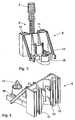
- Fig. 1 the chassis of a toy vehicle 1 is shown in the form of a tractor.
- the chassis consists of two injection-molded plastic halves 2, 3, which are interlocked during assembly.
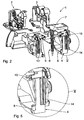
- a height-adjustable rear coupling carriage 5 is arranged, which is shown in detail in FIGS. 3 and 4.
- the spindle 6 is mounted on its underside in a cup-shaped bearing 8 at the lower end of the stern 4 and on its upper side via two claw-like projections 9, 10 on each chassis half 2, 3, which is located at Locking the chassis halves 2, 3 supplement due to their height offset to a ring-closed bearing.
- the rear coupling slide 5 is provided with two mutually parallel, preferably T-shaped recesses in cross-section slide guides 11, 12, in the arranged at the rear 4, in cross-section corresponding T-shaped slide receiving guides 13, 14 engage, so that a defined guide system is provided , which is subject to an exact vertical adjustment.
- the adjustment is accomplished in that between the two slide guides 11, 12 is arranged for locking elastically expandable spindle nut 15 so that upon rotation of the spindle 6 by means of the knob 7, the spindle nut 15 and with it the rear coupling slide 5 are moved up and down , Due to the Aufsp Sonus the spindle nut 15 an overload protection is given at the same time.
- a coupling pin 17 is fastened via a holding arrangement 16, which is height-adjusted together with the rear coupling carriage 5 so that its position can be optimally adapted to the position of any coupling eye of a trailer.
Landscapes
- Toys (AREA)
Description
- Die Erfindung richtet sich auf ein Spielzeug-Fahrzeug mit einer Anhängerkupplung umfassend einen sich im Abstand vom Fahrzeugheck vertikal erstreckenden Kupplungszapfen. Derartige Spielzeug-Fahrzeuge sind aus DE 296 08 600 U oder aus US-A-6095351 bekannt.
- An einem solchen Kupplungszapfen können Anhänger zum Transport von Lasten, in Form von Zusatzgeräten und dergleichen angehängt werden.
- Voraussetzung für eine optimale Übertragung der Zugkraft ist, dass die Kupplungsöse des Anhängers und der Kupplungszapfen des Zugfahrzeugs sich in gleicher Höhe befinden. Ist der Kupplungszapfen zu tief angeordnet, besteht die Gefahr, dass der Anhänger sich selbstständig abkuppelt, insbesondere wenn Unebenheiten überfahren werden. Ist der Kupplungszapfen und der den Kupplungszapfen umgebende Kupplungsteller relativ zur Anhängeröse zu hoch, kann entweder der Deichsel verklemmen, sodass die Bewegung beim Kurvenfahren gestört wird, oder die Räder des Anhängers werden ganz oder teilweise angehoben. Insbesondere landwirtschaftliche Anbaugeräte bedürfen oftmals einer höhenverstellbaren Anhängevorrichtung am Zugfahrzeug, um diese für die Fahrt, zum Beispiel auf der Straße, anzuheben, um so ausweichende Bodenfreiheit zu gewährleisten.
- Hiervon ausgehend liegt der Erfindung die Aufgabe zu Grunde, die Anhänger-Kupplung eines Spielfahrzeugs so auszugestalten, dass sie an unterschiedliche Anhänger- bzw. Kupplungsösen-Höhen anpassbar ist, sodass eine definierte und zuverlässige Übertragung der Zugkraft erreicht wird.
- Diese Aufgabe wird erfindungsgemäß dadurch gelöst, dass der Kupplungszapfen höhenverstellbar gelagert ist. Es ist dementsprechend möglich, die Höhe des Kupplungszapfens angepasst an einen bestimmten Anhänger so einzustellen, dass die Kupplungsöse vom Kupplungszapfen höhengleich durchsetzt wird.
- Vorzugsweise ist vorgesehen, dass der Kupplungszapfen an einem Heckkupplungsschlitten angeordnet ist, der insbesondere mittels einer Spindel höhenverstellbar gelagert ist.
- Der Heckkupplungsschlitten kann mit Vorteil über zwei zueinander parallele Schlittenführungen und korrespondierende Schlittenaufnahmeführungen am Heck vertikal geführt gelagert sein.
- Herstellungstechnisch ist es günstig, das Chassis des Fahrzeugs aus zwei ineinander verrastbaren Längs-Hälften zusammen zu setzen. Eine obere Führung für die Spindel kann dann durch je eine an je einer Chassis-Hälfte angeordnete, sich beim Verrasten der Chassis-Hälften kreisförmig mit der jeweils anderen ergänzende Klaue gebildet sein.
- An dem Heckkupplungsschlitten kann eine plastisch aufweitbare Spindelmutter zwischen den Schlittenführungen angeordnet sein, in die dementsprechend die Spindel einrastbar ist.
- Weiterhin ist am Heck vorteilhafter Weise ein tassenförmiges unteres Spindellager vorgesehen.
- Nachfolgend wird die Erfindung an Hand eines bevorzugten Ausführungsbeispiels in Verbindung mit der Zeichnung näher erläutert. Dabei zeigen:
- Fig. 1
- eine perspektivische Ansicht des Fahrgestells eines erfindungsgemäßen Spielzeug-Fahrzeugs,
- Fig. 2
- eine Fig. 1 entsprechende Darstellung, wobei die beiden ineinander verrastbaren Hälften des Fahrgestells im getrennten Zustand dargestellt sind,
- Fig. 3
- eine perspektivische Ansicht des höhenverstellbaren Kupplungs-Schlittens von hinten,
- Fig. 4
- eine Fig. 3 entsprechende Ansicht von vorne und
- Fig. 5
- eine vergrößerte Darstellung des Bereichs V in Fig. 2.
- In Fig. 1 ist das Fahrgestell eines Spielzeug-Fahrzeugs 1 in Form eines Traktors dargestellt. Das Fahrgestell besteht aus zwei aus Kunststoff gespritzten Hälfen 2, 3, welche bei der Montage ineinander verrastbar sind.
- An dem in Fig. 5 vergrößert dargestellten Heck 4 des Fahrzeugs 1 ist ein höhenverstellbarer Heckkupplungsschlitten 5 angeordnet, der in Fig. 3 und Fig. 4 im Einzelnen dargestellt ist.
- Zur Höhen-Verstellung des Heckkupplungsschlittens 5 dient eine Gewindespindel 6 mit einem Betätigungsknopf 7 an ihrer Oberseite.
- Die Spindel 6 ist an ihrer Unterseite in einem tassenförmigen Lager 8 am unteren Ende des Hecks 4 und an ihrer Oberseite über zwei klauenartige Ansätze 9, 10 an jeder Fahrgestellhälfte 2, 3 gelagert, welche sich beim Verrasten der Fahrgestellhälften 2, 3 auf Grund ihres Höhenversatzes zu einem ringförmig geschlossenen Lager ergänzen.
- Der Heckkupplungsschlitten 5 ist mit zwei parallel zueinander verlaufenden, im Querschnitt vorzugsweise T-förmige Ausnehmungen aufweisenden Schlittenführungen 11, 12 versehen, in die am Heck 4 angeordnete, im Querschnitt korrespondierend T-förmig ausgebildete Schlittenaufnahmeführungen 13, 14 eingreifen, sodass ein definiertes Führungssystem geschaffen wird, welches eine exakte vertikale Verstellung überliegt.
- Die Verstellung wird dadurch bewerkstelligt, dass zwischen den beiden Schlittenführungen 11, 12 eine zum Einrasten elastisch aufspreizbare Spindelmutter 15 angeordnet ist, sodass bei einem Verdrehen der Spindel 6 mit Hilfe des Knopfes 7 die Spindelmutter 15 und mit ihr der Heckkupplungsschlitten 5 auf und ab bewegt werden. Durch die Aufspreizbarkeit der Spindelmutter 15 ist gleichzeitig ein Überlastschutz gegeben.
- An dem Heckkupplungsschlitten 5 ist über eine Halteanordnung 16 ein Kupplungszapfen 17 befestigt, der zusammen mit dem Heckkupplungsschlitten 5 höhenverstellt wird, sodass seine Position an die Position einer beliebigen Kupplungsöse eines Anhängers optimal anpassbar ist.
Claims (7)
- Spielzeug-Fahrzeug (1) mit einer Anhängerkupplung, umfassend einen sich im Abstand vom Fahrzeugheck vertikal erstreckenden Kupplungszapfen (17), dadurch gekennzeichnet, dass der Kupplungszapfen (17) mittels einer Spindel (6) höhenverstellbar gelagert ist, wobei eine Führung für die Spindel (6) durch zwei annähernd halbkreisförmige Klauen (9, 10) gebildet ist.
- Spielzeug-Fahrzeug nach Anspruch 1, dadurch gekennzeichnet, dass der Kupplungszapfen (17) an einem Heckkupplungsschlitten (5) angeordnet ist, der höhenverstellbar gelagert ist.
- Spielzeug-Fahrzeug nach Anspruch 2, dadurch gekennzeichnet, dass der Heckkupplungsschlitten (5) mittels einer Spindel (6) höhenverstellbar gelagert ist.
- Spielzeug-Fahrzeug nach Anspruch 2, dadurch gekennzeichnet, dass der Heckkupplungsschlitten (5) über zwei zueinander parallele Schlittenführungen (11, 12) und korrespondierende Schlittenaufnahmeführungen (13, 14) am Heck (4) vertikal geführt gelagert ist.
- Spielzeug-Fahrzeug nach Anspruch 1, wobei das Chassis des Fahrzeugs aus zwei ineinander verrastbaren Längs-Hälften besteht, dadurch gekennzeichnet, dass eine obere Führung für die Spindel (6) durch je eine an je einer Chassis-Hälfte (2, 3) angeordnete, sich beim Verrasten der Chassis-Hälften (2, 3) mit der jeweils anderen kreisförmig ergänzende Klaue (9, 10) gebildet ist.
- Spielzeug-Fahrzeug nach Anspruch 2, dadurch gekennzeichnet, dass eine elastisch aufweitbare zweiteilige Spindelmutter (15) an dem Heckkupplungsschlitten (5) zwischen den Schlittenführungen (11, 12) angeordnet ist.
- Spielzeug-Fahrzeug nach Anspruch 1, dadurch gekennzeichnet, dass am Heck (4) ein tassenförmiges unteres Spindellager (8) vorgesehen ist.
Applications Claiming Priority (2)
| Application Number | Priority Date | Filing Date | Title |
|---|---|---|---|
| DE202004001294U | 2004-01-29 | ||
| DE200420001294 DE202004001294U1 (de) | 2004-01-29 | 2004-01-29 | Spielzeug-Fahrzeug mit Anhängerkupplung |
Publications (2)
| Publication Number | Publication Date |
|---|---|
| EP1559462A1 EP1559462A1 (de) | 2005-08-03 |
| EP1559462B1 true EP1559462B1 (de) | 2007-02-28 |
Family
ID=32087859
Family Applications (1)
| Application Number | Title | Priority Date | Filing Date |
|---|---|---|---|
| EP20040030067 Expired - Lifetime EP1559462B1 (de) | 2004-01-29 | 2004-12-18 | Spielzeug-Fahrzeug mit Anhängerkupplung |
Country Status (2)
| Country | Link |
|---|---|
| EP (1) | EP1559462B1 (de) |
| DE (2) | DE202004001294U1 (de) |
Families Citing this family (1)
| Publication number | Priority date | Publication date | Assignee | Title |
|---|---|---|---|---|
| DE102015001082A1 (de) * | 2015-01-28 | 2016-07-28 | Sieper Gmbh | Modelltraktor mit einer Kupplung zur Aufnahme wenigstens eines Anbaugerätes und/oder Anhängers |
Family Cites Families (4)
| Publication number | Priority date | Publication date | Assignee | Title |
|---|---|---|---|---|
| US720687A (en) * | 1902-09-04 | 1903-02-17 | Wilhelm Graupner | Car-coupling. |
| US2578368A (en) * | 1946-11-23 | 1951-12-11 | Nehrke Charles | Toy coupling |
| DE4302970C1 (de) * | 1993-02-03 | 1994-06-01 | Lehmann E P Patentwerk | Ferngesteuerte Kupplung für elektrische Spiel- und Modellbahnen |
| DE19815216A1 (de) * | 1997-05-02 | 1998-11-05 | Elfriede Roessler | Kupplungsvorrichtung für Modelleisenbahn |
-
2004
- 2004-01-29 DE DE200420001294 patent/DE202004001294U1/de not_active Expired - Lifetime
- 2004-12-18 EP EP20040030067 patent/EP1559462B1/de not_active Expired - Lifetime
- 2004-12-18 DE DE200450003028 patent/DE502004003028D1/de not_active Expired - Lifetime
Also Published As
| Publication number | Publication date |
|---|---|
| DE502004003028D1 (de) | 2007-04-12 |
| DE202004001294U1 (de) | 2004-04-01 |
| EP1559462A1 (de) | 2005-08-03 |
Similar Documents
| Publication | Publication Date | Title |
|---|---|---|
| DE102004024333B4 (de) | Steckverbindungen | |
| DE2443809B2 (de) | Plattenfoermige ballastgewichte, insbesondere fuer landwirtschaftlich nutzbare motorfahrzeuge | |
| DE102015111095B4 (de) | Fahrzeuganhänger mit einer hydraulisch lenkbaren Deichsel | |
| DE19905676B4 (de) | Zugdeichsel für Zentralachsanhänger | |
| EP3143861B1 (de) | Landwirtschaftliches mähwerk und zuggespann und verfahren zum betreiben des mähwerks | |
| EP2404814B1 (de) | Kotflügel für ein Nutzfahrzeug | |
| DE202008012180U1 (de) | Transportsystem | |
| EP1559462B1 (de) | Spielzeug-Fahrzeug mit Anhängerkupplung | |
| EP3398842B1 (de) | Dolly für sattelauflieger | |
| DE102008025633B4 (de) | Flurförderzeug | |
| EP3260358B1 (de) | Nutzfahrzeugchassis | |
| DE102010053083A1 (de) | Sattelkupplung mit einstellbarer Höhe | |
| EP3392067A1 (de) | Kopplungseinrichtung eines routenzugs | |
| EP3254892A1 (de) | Trailerzuganhänger | |
| WO2020169327A1 (de) | Kopplungseinrichtung eines routenzugs | |
| DE2319308B1 (de) | Maschine zum Ausbringen von verteilbarem Material | |
| DE10024916C2 (de) | Schutzvorrichtung für eine Kraftfahrzeugkarosserie beim Ankuppeln von Anhängern | |
| EP2955039B1 (de) | Aufnahmevorrichtung für Fahrzeuganhänger | |
| DE102006020921B4 (de) | Kupplung für Transportanhänger | |
| DE10030263A1 (de) | Anhängevorrichtung | |
| DE102020105001A1 (de) | Anhängevorrichtung für Zugfahrzeuge | |
| DE202013005353U1 (de) | Verstellbarer Anfahrschutz für Zugvorrichtungen mit Zwangslenkung | |
| DE4413019C2 (de) | Fahrzeug mit einem spurtreuen Fahrwerk und einer Anhängevorrichtung | |
| DE202009015102U1 (de) | Aufliegerfahrzeug mit einer Lenkvorrichtung | |
| EP3378754A1 (de) | Fahrradanhänger mit verschwenkbarer deichsel |
Legal Events
| Date | Code | Title | Description |
|---|---|---|---|
| PUAI | Public reference made under article 153(3) epc to a published international application that has entered the european phase |
Free format text: ORIGINAL CODE: 0009012 |
|
| AK | Designated contracting states |
Kind code of ref document: A1 Designated state(s): AT BE BG CH CY CZ DE DK EE ES FI FR GB GR HU IE IS IT LI LT LU MC NL PL PT RO SE SI SK TR |
|
| AX | Request for extension of the european patent |
Extension state: AL BA HR LV MK YU |
|
| 17P | Request for examination filed |
Effective date: 20050617 |
|
| GRAP | Despatch of communication of intention to grant a patent |
Free format text: ORIGINAL CODE: EPIDOSNIGR1 |
|
| GRAS | Grant fee paid |
Free format text: ORIGINAL CODE: EPIDOSNIGR3 |
|
| AKX | Designation fees paid |
Designated state(s): BE DE FR GB NL |
|
| GRAA | (expected) grant |
Free format text: ORIGINAL CODE: 0009210 |
|
| AK | Designated contracting states |
Kind code of ref document: B1 Designated state(s): BE DE FR GB NL |
|
| REG | Reference to a national code |
Ref country code: GB Ref legal event code: FG4D Free format text: NOT ENGLISH |
|
| REF | Corresponds to: |
Ref document number: 502004003028 Country of ref document: DE Date of ref document: 20070412 Kind code of ref document: P |
|
| GBT | Gb: translation of ep patent filed (gb section 77(6)(a)/1977) |
Effective date: 20070420 |
|
| ET | Fr: translation filed | ||
| PLBE | No opposition filed within time limit |
Free format text: ORIGINAL CODE: 0009261 |
|
| STAA | Information on the status of an ep patent application or granted ep patent |
Free format text: STATUS: NO OPPOSITION FILED WITHIN TIME LIMIT |
|
| 26N | No opposition filed |
Effective date: 20071129 |
|
| REG | Reference to a national code |
Ref country code: FR Ref legal event code: PLFP Year of fee payment: 12 |
|
| REG | Reference to a national code |
Ref country code: FR Ref legal event code: PLFP Year of fee payment: 13 |
|
| REG | Reference to a national code |
Ref country code: FR Ref legal event code: PLFP Year of fee payment: 14 |
|
| PGFP | Annual fee paid to national office [announced via postgrant information from national office to epo] |
Ref country code: NL Payment date: 20221220 Year of fee payment: 19 Ref country code: GB Payment date: 20221222 Year of fee payment: 19 Ref country code: FR Payment date: 20221220 Year of fee payment: 19 |
|
| PGFP | Annual fee paid to national office [announced via postgrant information from national office to epo] |
Ref country code: BE Payment date: 20221220 Year of fee payment: 19 |
|
| PGFP | Annual fee paid to national office [announced via postgrant information from national office to epo] |
Ref country code: DE Payment date: 20230223 Year of fee payment: 19 |
|
| P01 | Opt-out of the competence of the unified patent court (upc) registered |
Effective date: 20230519 |
|
| REG | Reference to a national code |
Ref country code: DE Ref legal event code: R119 Ref document number: 502004003028 Country of ref document: DE |
|
| REG | Reference to a national code |
Ref country code: NL Ref legal event code: MM Effective date: 20240101 |
|
| GBPC | Gb: european patent ceased through non-payment of renewal fee |
Effective date: 20231218 |
|
| REG | Reference to a national code |
Ref country code: BE Ref legal event code: MM Effective date: 20231231 |
|
| PG25 | Lapsed in a contracting state [announced via postgrant information from national office to epo] |
Ref country code: NL Free format text: LAPSE BECAUSE OF NON-PAYMENT OF DUE FEES Effective date: 20240101 |
|
| PG25 | Lapsed in a contracting state [announced via postgrant information from national office to epo] |
Ref country code: NL Free format text: LAPSE BECAUSE OF NON-PAYMENT OF DUE FEES Effective date: 20240101 |
|
| PG25 | Lapsed in a contracting state [announced via postgrant information from national office to epo] |
Ref country code: DE Free format text: LAPSE BECAUSE OF NON-PAYMENT OF DUE FEES Effective date: 20240702 |
|
| PG25 | Lapsed in a contracting state [announced via postgrant information from national office to epo] |
Ref country code: GB Free format text: LAPSE BECAUSE OF NON-PAYMENT OF DUE FEES Effective date: 20231218 |
|
| PG25 | Lapsed in a contracting state [announced via postgrant information from national office to epo] |
Ref country code: BE Free format text: LAPSE BECAUSE OF NON-PAYMENT OF DUE FEES Effective date: 20231231 |
|
| PG25 | Lapsed in a contracting state [announced via postgrant information from national office to epo] |
Ref country code: FR Free format text: LAPSE BECAUSE OF NON-PAYMENT OF DUE FEES Effective date: 20231231 |
|
| PG25 | Lapsed in a contracting state [announced via postgrant information from national office to epo] |
Ref country code: GB Free format text: LAPSE BECAUSE OF NON-PAYMENT OF DUE FEES Effective date: 20231218 Ref country code: FR Free format text: LAPSE BECAUSE OF NON-PAYMENT OF DUE FEES Effective date: 20231231 Ref country code: DE Free format text: LAPSE BECAUSE OF NON-PAYMENT OF DUE FEES Effective date: 20240702 Ref country code: BE Free format text: LAPSE BECAUSE OF NON-PAYMENT OF DUE FEES Effective date: 20231231 |