EP1559462A1 - Spielzeug-Fahrzeug mit Anhängerkupplung - Google Patents
Spielzeug-Fahrzeug mit Anhängerkupplung Download PDFInfo
- Publication number
- EP1559462A1 EP1559462A1 EP04030067A EP04030067A EP1559462A1 EP 1559462 A1 EP1559462 A1 EP 1559462A1 EP 04030067 A EP04030067 A EP 04030067A EP 04030067 A EP04030067 A EP 04030067A EP 1559462 A1 EP1559462 A1 EP 1559462A1
- Authority
- EP
- European Patent Office
- Prior art keywords
- toy vehicle
- coupling
- vehicle according
- carriage
- spindle
- Prior art date
- Legal status (The legal status is an assumption and is not a legal conclusion. Google has not performed a legal analysis and makes no representation as to the accuracy of the status listed.)
- Granted
Links
- 230000008878 coupling Effects 0.000 claims abstract description 32
- 238000010168 coupling process Methods 0.000 claims abstract description 32
- 238000005859 coupling reaction Methods 0.000 claims abstract description 32
- 230000000295 complement effect Effects 0.000 claims description 3
- 210000000078 claw Anatomy 0.000 claims description 2
- 238000000465 moulding Methods 0.000 abstract 3
- 230000005540 biological transmission Effects 0.000 description 2
- 238000005516 engineering process Methods 0.000 description 1
- 238000004519 manufacturing process Methods 0.000 description 1
- 239000002991 molded plastic Substances 0.000 description 1
Images


Classifications
-
- A—HUMAN NECESSITIES
- A63—SPORTS; GAMES; AMUSEMENTS
- A63H—TOYS, e.g. TOPS, DOLLS, HOOPS OR BUILDING BLOCKS
- A63H19/00—Model railways
- A63H19/16—Parts for model railway vehicles
- A63H19/18—Car coupling or uncoupling mechanisms
-
- A—HUMAN NECESSITIES
- A63—SPORTS; GAMES; AMUSEMENTS
- A63H—TOYS, e.g. TOPS, DOLLS, HOOPS OR BUILDING BLOCKS
- A63H17/00—Toy vehicles, e.g. with self-drive; ; Cranes, winches or the like; Accessories therefor
- A63H17/26—Details; Accessories
- A63H17/264—Coupling mechanisms
Definitions
- the invention is directed to a toy vehicle with a trailer hitch comprising a vertical distance from the rear of the vehicle extending coupling pin.
- a toy vehicle is out DE 296 08 600 U known.
- Prerequisite for an optimal transmission of traction is that the Coupling eye of the trailer and the coupling pin of the towing vehicle are at the same height. Is the coupling pin too low, there is a risk that the trailer disconnects itself, especially when bumps are run over. Is the coupling pin and the clutch pin surrounding the clutch actuator relative too high to the eye, either the drawbar can jam, so the movement is disturbed when cornering, or the wheels of the trailer be raised in whole or in part. In particular agricultural Attachments often require a height-adjustable hitch on the towing vehicle to get this for the ride, for example on the Road to lift, so as to ensure evasive ground clearance.
- the invention is based on the object, the trailer coupling a toy vehicle in such a way that they to different Trailer or coupling eyelet heights is customizable, so a defined and reliable transmission of the traction is achieved.
- the coupling pin is mounted adjustable in height. It is accordingly possible, the Height of the coupling pin adapted to a particular trailer so adjust that the coupling eye of the coupling pin equal in height is enforced.
- the coupling pin on a rear coupling slide is arranged, in particular by means of a spindle is mounted adjustable in height.
- the rear coupling slide can advantageously via two parallel Slide guides and corresponding slide receiving guides be stored vertically guided at the rear.
- On the rear coupling slide can be a plastically expandable spindle nut be arranged between the carriage guides, in the accordingly the spindle is latched.
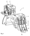
- Fig. 1 the chassis of a toy vehicle 1 in the form of a Tractor shown.
- the chassis consists of two molded plastic Halves 2, 3, which are locked into one another during assembly.
- FIG. 5 shown enlarged rear 4 of the vehicle 1 is a height-adjustable rear coupling slide 5 arranged in Fig. 3 and Fig. 4 is shown in detail.
- the spindle 6 is on its underside in a cup-shaped bearing 8 on lower end of the tail 4 and at its top over two claw-like Lugs 9, 10 mounted on each chassis half 2, 3, which at the Locking the chassis halves 2, 3 due to their height offset to complement a ring-closed camp.
- the rear coupling carriage 5 is provided with two mutually parallel, in cross-section preferably having T-shaped recesses Carriage guides 11, 12 provided in the rear 4 arranged in the Cross section corresponding T-shaped slide receiving guides 13, 14 intervene, creating a defined guidance system which is subject to an exact vertical adjustment.
- the adjustment is accomplished by the fact that between the two Slide guides 11, 12 a for clamping elastically expandable spindle nut 15 is arranged so that upon rotation of the spindle 6 with Help the knob 7, the spindle nut 15 and with it the rear coupling carriage 5 are moved up and down. Due to the expandability of Spindle nut 15 is given an overload protection at the same time.
- a Coupling pin 17 attached, which together with the rear coupling carriage 5 is adjusted in height, so that its position to the position of Any coupling eye of a trailer is optimally adaptable.
Landscapes
- Toys (AREA)
Abstract
Description
- Fig. 1
- eine perspektivische Ansicht des Fahrgestells eines erfindungsgemäßen Spielzeug-Fahrzeugs,
- Fig. 2
- eine Fig. 1 entsprechende Darstellung, wobei die beiden ineinander verrastbaren Hälften des Fahrgestells im getrennten Zustand dargestellt sind,
- Fig. 3
- eine perspektivische Ansicht des höhenverstellbaren Kupplungs-Schlittens von hinten,
- Fig. 4
- eine Fig. 3 entsprechende Ansicht von vorne und
- Fig. 5
- eine vergrößerte Darstellung des Bereichs V in Fig. 2.
Claims (7)
- Spielzeug-Fahrzeug mit einer Anhängerkupplung, umfassend einen sich im Abstand vom Fahrzeugheck vertikal erstreckenden Kupplungszapfen, dadurch gekennzeichnet, dass der Kupplungszapfen (17) höhenverstellbar gelagert ist.
- Spielzeug-Fahrzeug nach Anspruch 1, dadurch gekennzeichnet, dass der Kupplungszapfen (17) an einem Heckkupplungsschlitten (5) angeordnet ist, der höhenverstellbar gelagert ist.
- Spielzeug-Fahrzeug nach Anspruch 2, dadurch gekennzeichnet, dass der Heckkupplungsschlitten (5) mittels einer Spindel (6) höhenverstellbar gelagert ist.
- Spielzeug-Fahrzeug nach Anspruch 2, dadurch gekennzeichnet, dass der Heckkupplungsschlitten (5) über zwei zueinander parallele Schlittenführungen (11, 12) und korrespondierende Schlittenaufnahmeführungen (13, 14) am Heck (4) vertikal geführt gelagert ist.
- Spielzeug-Fahrzeug nach Anspruch 1, wobei das Chassis des Fahrzeugs aus zwei ineinander verrastbaren Längs-Hälften besteht, dadurch gekennzeichnet, dass eine obere Führung für die Spindel (6) durch je eine an je einer Chassis-Hälfte (2, 3) angeordnete, sich beim Verrasten der Chassis-Hälften (2, 3) mit der jeweils anderen kreisförmig ergänzende Klaue (9, 10) gebildet ist.
- Spielzeug-Fahrzeug nach Anspruch 2, dadurch gekennzeichnet, dass eine elastisch aufweitbare zweiteilige Spindelmutter (15) an dem Heckkupplungsschlitten (5) zwischen den Schlittenführungen (11, 12) angeordnet ist.
- Spielzeug-Fahrzeug nach Anspruch 1, dadurch gekennzeichnet, dass am Heck (4) ein tassenförmiges unteres Spindellager (8) vorgesehen ist.
Applications Claiming Priority (2)
| Application Number | Priority Date | Filing Date | Title |
|---|---|---|---|
| DE202004001294U | 2004-01-29 | ||
| DE200420001294 DE202004001294U1 (de) | 2004-01-29 | 2004-01-29 | Spielzeug-Fahrzeug mit Anhängerkupplung |
Publications (2)
| Publication Number | Publication Date |
|---|---|
| EP1559462A1 true EP1559462A1 (de) | 2005-08-03 |
| EP1559462B1 EP1559462B1 (de) | 2007-02-28 |
Family
ID=32087859
Family Applications (1)
| Application Number | Title | Priority Date | Filing Date |
|---|---|---|---|
| EP20040030067 Expired - Lifetime EP1559462B1 (de) | 2004-01-29 | 2004-12-18 | Spielzeug-Fahrzeug mit Anhängerkupplung |
Country Status (2)
| Country | Link |
|---|---|
| EP (1) | EP1559462B1 (de) |
| DE (2) | DE202004001294U1 (de) |
Families Citing this family (1)
| Publication number | Priority date | Publication date | Assignee | Title |
|---|---|---|---|---|
| DE102015001082A1 (de) * | 2015-01-28 | 2016-07-28 | Sieper Gmbh | Modelltraktor mit einer Kupplung zur Aufnahme wenigstens eines Anbaugerätes und/oder Anhängers |
Citations (4)
| Publication number | Priority date | Publication date | Assignee | Title |
|---|---|---|---|---|
| US720687A (en) * | 1902-09-04 | 1903-02-17 | Wilhelm Graupner | Car-coupling. |
| US2578368A (en) * | 1946-11-23 | 1951-12-11 | Nehrke Charles | Toy coupling |
| US5423439A (en) * | 1993-02-03 | 1995-06-13 | Ernst Paul Lehmann Patentwerk | Remote-controlled uncoupling for electric toy and model trains |
| US6095351A (en) * | 1997-05-02 | 2000-08-01 | Roessler; Elfriede | Coupling device for model railway |
-
2004
- 2004-01-29 DE DE200420001294 patent/DE202004001294U1/de not_active Expired - Lifetime
- 2004-12-18 EP EP20040030067 patent/EP1559462B1/de not_active Expired - Lifetime
- 2004-12-18 DE DE200450003028 patent/DE502004003028D1/de not_active Expired - Lifetime
Patent Citations (4)
| Publication number | Priority date | Publication date | Assignee | Title |
|---|---|---|---|---|
| US720687A (en) * | 1902-09-04 | 1903-02-17 | Wilhelm Graupner | Car-coupling. |
| US2578368A (en) * | 1946-11-23 | 1951-12-11 | Nehrke Charles | Toy coupling |
| US5423439A (en) * | 1993-02-03 | 1995-06-13 | Ernst Paul Lehmann Patentwerk | Remote-controlled uncoupling for electric toy and model trains |
| US6095351A (en) * | 1997-05-02 | 2000-08-01 | Roessler; Elfriede | Coupling device for model railway |
Also Published As
| Publication number | Publication date |
|---|---|
| EP1559462B1 (de) | 2007-02-28 |
| DE502004003028D1 (de) | 2007-04-12 |
| DE202004001294U1 (de) | 2004-04-01 |
Similar Documents
| Publication | Publication Date | Title |
|---|---|---|
| EP1902871A1 (de) | Anhängekupplung | |
| DE102015111095B4 (de) | Fahrzeuganhänger mit einer hydraulisch lenkbaren Deichsel | |
| EP2918484A2 (de) | Anhänger für einen Routenzug | |
| EP3143861B1 (de) | Landwirtschaftliches mähwerk und zuggespann und verfahren zum betreiben des mähwerks | |
| EP2404814B1 (de) | Kotflügel für ein Nutzfahrzeug | |
| AT505395B1 (de) | Transportsystem | |
| EP1972500B2 (de) | Lastenträger für ein Kraftfahrzeug | |
| EP1559462B1 (de) | Spielzeug-Fahrzeug mit Anhängerkupplung | |
| EP2805593A1 (de) | Lagesicherungsvorrichtung und damit ausgerüstete Geräteeinheit | |
| DE19508039A1 (de) | Fahrzeug mit einem am Bug beweglich angeordneten Spoiler | |
| EP3260358B1 (de) | Nutzfahrzeugchassis | |
| EP3392067B1 (de) | Kopplungseinrichtung eines routenzugs | |
| DE102007007166B4 (de) | Transportfahrzeug mit Hubladebühne und verstellbarem Unterfahrschutz | |
| DE102010053083A1 (de) | Sattelkupplung mit einstellbarer Höhe | |
| EP3254892A1 (de) | Trailerzuganhänger | |
| WO2020169327A1 (de) | Kopplungseinrichtung eines routenzugs | |
| DE2319308B1 (de) | Maschine zum Ausbringen von verteilbarem Material | |
| DE202008000162U1 (de) | Zugwagen, insbesondere für den Pferdesport | |
| DE10024916C2 (de) | Schutzvorrichtung für eine Kraftfahrzeugkarosserie beim Ankuppeln von Anhängern | |
| DE102006020921B4 (de) | Kupplung für Transportanhänger | |
| EP2955039B1 (de) | Aufnahmevorrichtung für Fahrzeuganhänger | |
| DE10030263A1 (de) | Anhängevorrichtung | |
| EP3666558B1 (de) | Anhängerkupplung | |
| DE4413019C2 (de) | Fahrzeug mit einem spurtreuen Fahrwerk und einer Anhängevorrichtung | |
| EP4173855A1 (de) | Anhängevorrichtung und aufnahmevorrichtung |
Legal Events
| Date | Code | Title | Description |
|---|---|---|---|
| PUAI | Public reference made under article 153(3) epc to a published international application that has entered the european phase |
Free format text: ORIGINAL CODE: 0009012 |
|
| AK | Designated contracting states |
Kind code of ref document: A1 Designated state(s): AT BE BG CH CY CZ DE DK EE ES FI FR GB GR HU IE IS IT LI LT LU MC NL PL PT RO SE SI SK TR |
|
| AX | Request for extension of the european patent |
Extension state: AL BA HR LV MK YU |
|
| 17P | Request for examination filed |
Effective date: 20050617 |
|
| GRAP | Despatch of communication of intention to grant a patent |
Free format text: ORIGINAL CODE: EPIDOSNIGR1 |
|
| GRAS | Grant fee paid |
Free format text: ORIGINAL CODE: EPIDOSNIGR3 |
|
| AKX | Designation fees paid |
Designated state(s): BE DE FR GB NL |
|
| GRAA | (expected) grant |
Free format text: ORIGINAL CODE: 0009210 |
|
| AK | Designated contracting states |
Kind code of ref document: B1 Designated state(s): BE DE FR GB NL |
|
| REG | Reference to a national code |
Ref country code: GB Ref legal event code: FG4D Free format text: NOT ENGLISH |
|
| REF | Corresponds to: |
Ref document number: 502004003028 Country of ref document: DE Date of ref document: 20070412 Kind code of ref document: P |
|
| GBT | Gb: translation of ep patent filed (gb section 77(6)(a)/1977) |
Effective date: 20070420 |
|
| ET | Fr: translation filed | ||
| PLBE | No opposition filed within time limit |
Free format text: ORIGINAL CODE: 0009261 |
|
| STAA | Information on the status of an ep patent application or granted ep patent |
Free format text: STATUS: NO OPPOSITION FILED WITHIN TIME LIMIT |
|
| 26N | No opposition filed |
Effective date: 20071129 |
|
| REG | Reference to a national code |
Ref country code: FR Ref legal event code: PLFP Year of fee payment: 12 |
|
| REG | Reference to a national code |
Ref country code: FR Ref legal event code: PLFP Year of fee payment: 13 |
|
| REG | Reference to a national code |
Ref country code: FR Ref legal event code: PLFP Year of fee payment: 14 |
|
| PGFP | Annual fee paid to national office [announced via postgrant information from national office to epo] |
Ref country code: NL Payment date: 20221220 Year of fee payment: 19 Ref country code: GB Payment date: 20221222 Year of fee payment: 19 Ref country code: FR Payment date: 20221220 Year of fee payment: 19 |
|
| PGFP | Annual fee paid to national office [announced via postgrant information from national office to epo] |
Ref country code: BE Payment date: 20221220 Year of fee payment: 19 |
|
| PGFP | Annual fee paid to national office [announced via postgrant information from national office to epo] |
Ref country code: DE Payment date: 20230223 Year of fee payment: 19 |
|
| P01 | Opt-out of the competence of the unified patent court (upc) registered |
Effective date: 20230519 |
|
| REG | Reference to a national code |
Ref country code: DE Ref legal event code: R119 Ref document number: 502004003028 Country of ref document: DE |
|
| REG | Reference to a national code |
Ref country code: NL Ref legal event code: MM Effective date: 20240101 |
|
| GBPC | Gb: european patent ceased through non-payment of renewal fee |
Effective date: 20231218 |
|
| REG | Reference to a national code |
Ref country code: BE Ref legal event code: MM Effective date: 20231231 |
|
| PG25 | Lapsed in a contracting state [announced via postgrant information from national office to epo] |
Ref country code: NL Free format text: LAPSE BECAUSE OF NON-PAYMENT OF DUE FEES Effective date: 20240101 |
|
| PG25 | Lapsed in a contracting state [announced via postgrant information from national office to epo] |
Ref country code: NL Free format text: LAPSE BECAUSE OF NON-PAYMENT OF DUE FEES Effective date: 20240101 |
|
| PG25 | Lapsed in a contracting state [announced via postgrant information from national office to epo] |
Ref country code: DE Free format text: LAPSE BECAUSE OF NON-PAYMENT OF DUE FEES Effective date: 20240702 |
|
| PG25 | Lapsed in a contracting state [announced via postgrant information from national office to epo] |
Ref country code: GB Free format text: LAPSE BECAUSE OF NON-PAYMENT OF DUE FEES Effective date: 20231218 |
|
| PG25 | Lapsed in a contracting state [announced via postgrant information from national office to epo] |
Ref country code: BE Free format text: LAPSE BECAUSE OF NON-PAYMENT OF DUE FEES Effective date: 20231231 |
|
| PG25 | Lapsed in a contracting state [announced via postgrant information from national office to epo] |
Ref country code: FR Free format text: LAPSE BECAUSE OF NON-PAYMENT OF DUE FEES Effective date: 20231231 |
|
| PG25 | Lapsed in a contracting state [announced via postgrant information from national office to epo] |
Ref country code: GB Free format text: LAPSE BECAUSE OF NON-PAYMENT OF DUE FEES Effective date: 20231218 Ref country code: FR Free format text: LAPSE BECAUSE OF NON-PAYMENT OF DUE FEES Effective date: 20231231 Ref country code: DE Free format text: LAPSE BECAUSE OF NON-PAYMENT OF DUE FEES Effective date: 20240702 Ref country code: BE Free format text: LAPSE BECAUSE OF NON-PAYMENT OF DUE FEES Effective date: 20231231 |