EP1558898B1 - Magnetisch induktiver durchflussmesser - Google Patents
Magnetisch induktiver durchflussmesser Download PDFInfo
- Publication number
- EP1558898B1 EP1558898B1 EP03782092A EP03782092A EP1558898B1 EP 1558898 B1 EP1558898 B1 EP 1558898B1 EP 03782092 A EP03782092 A EP 03782092A EP 03782092 A EP03782092 A EP 03782092A EP 1558898 B1 EP1558898 B1 EP 1558898B1
- Authority
- EP
- European Patent Office
- Prior art keywords
- measuring tube
- flowmeter according
- limb
- flow direction
- leg
- Prior art date
- Legal status (The legal status is an assumption and is not a legal conclusion. Google has not performed a legal analysis and makes no representation as to the accuracy of the status listed.)
- Expired - Lifetime
Links
- 230000001939 inductive effect Effects 0.000 title claims description 6
- 230000005291 magnetic effect Effects 0.000 claims description 58
- 238000005259 measurement Methods 0.000 claims description 16
- XEEYBQQBJWHFJM-UHFFFAOYSA-N Iron Chemical compound [Fe] XEEYBQQBJWHFJM-UHFFFAOYSA-N 0.000 claims description 14
- 230000004907 flux Effects 0.000 claims description 14
- 229910052742 iron Inorganic materials 0.000 claims description 6
- 239000000853 adhesive Substances 0.000 description 11
- 230000001070 adhesive effect Effects 0.000 description 11
- 238000005266 casting Methods 0.000 description 4
- 230000000694 effects Effects 0.000 description 4
- 239000012530 fluid Substances 0.000 description 4
- 150000001875 compounds Chemical class 0.000 description 3
- 230000004323 axial length Effects 0.000 description 2
- 238000006073 displacement reaction Methods 0.000 description 2
- 238000009826 distribution Methods 0.000 description 2
- 239000006247 magnetic powder Substances 0.000 description 2
- 230000009471 action Effects 0.000 description 1
- 238000004026 adhesive bonding Methods 0.000 description 1
- 239000002390 adhesive tape Substances 0.000 description 1
- 239000004020 conductor Substances 0.000 description 1
- 229910003460 diamond Inorganic materials 0.000 description 1
- 239000010432 diamond Substances 0.000 description 1
- 230000005611 electricity Effects 0.000 description 1
- 230000005294 ferromagnetic effect Effects 0.000 description 1
- 230000006872 improvement Effects 0.000 description 1
- 239000007788 liquid Substances 0.000 description 1
- 239000000463 material Substances 0.000 description 1
- 239000012811 non-conductive material Substances 0.000 description 1
- 238000004382 potting Methods 0.000 description 1
- 238000004804 winding Methods 0.000 description 1
Images


Classifications
-
- G—PHYSICS
- G01—MEASURING; TESTING
- G01F—MEASURING VOLUME, VOLUME FLOW, MASS FLOW OR LIQUID LEVEL; METERING BY VOLUME
- G01F1/00—Measuring the volume flow or mass flow of fluid or fluent solid material wherein the fluid passes through a meter in a continuous flow
- G01F1/56—Measuring the volume flow or mass flow of fluid or fluent solid material wherein the fluid passes through a meter in a continuous flow by using electric or magnetic effects
- G01F1/58—Measuring the volume flow or mass flow of fluid or fluent solid material wherein the fluid passes through a meter in a continuous flow by using electric or magnetic effects by electromagnetic flowmeters
- G01F1/586—Measuring the volume flow or mass flow of fluid or fluent solid material wherein the fluid passes through a meter in a continuous flow by using electric or magnetic effects by electromagnetic flowmeters constructions of coils, magnetic circuits, accessories therefor
Definitions
- the invention relates to a magnetic inductive flow meter with a measuring tube, an electrode assembly with electrodes, which are arranged on opposite sides of the measuring tube transversely to a flow direction through the measuring tube, and a coil assembly with at least one saddle coil, the axis transverse to the flow direction and transverse to the electrode assembly runs and has the four legs, of which two first legs parallel to the flow direction and two second legs in the circumferential direction of the measuring tube.
- a moving electrically conductive fluid flowing through the measuring tube generates a voltage between the electrodes of the electrode assembly when the coil assembly generates a magnetic field.
- the magnetic field is directed perpendicular to the flow direction.
- the voltage is taken perpendicular to the flow direction and perpendicular to the magnetic field.
- the voltage on the electrode assembly is then u.a. depending on the flow rate, from which in turn can be closed to the flow rate.
- the magnetic field extends over the entire cross-sectional area of the measuring tube.
- One way to accomplish this is to use a yoke or pole piece. The coil then generates a magnetic field which is distributed by the pole piece and then extends substantially uniformly over the cross section of the measuring tube.
- the coil arrangement has two saddle coils. Seen from above, the saddle coils in the broadest sense form a quadrilateral, of which two legs run parallel to the flow direction. The other two legs follow the curvature of the measuring tube. These legs may also have an arc or an angle in the axial direction, so that the saddle coil in plan view resembles a hexagon, so what a diamond looks like. Even with such saddle coils can be achieved largely satisfactory results.
- the invention has for its object to improve the accuracy of measurement in a measuring tube with a smaller diameter.
- a magneto-inductive flowmeter of the type mentioned in that between each first leg and the measuring tube in each case a magnetically conductive element is arranged, which receives a first part of the magnetic flux, wherein a second Part of the magnetic flux passes from an area surrounded by the saddle coil area past the element.
- the direction of the magnetic field is changed in the direction of the electrode.
- the magnetic field then better fills the cross section of the measuring tube.
- the measurement signal which can be picked up at the electrode assembly then rises as desired.
- one achieves this improvement of the measurement result by deflecting only part of the magnetic flux.
- Most of the magnetic flux in the area surrounded by the saddle coil remains undisturbed; H. it can spread in the cross section of the measuring tube without being influenced by a pole piece or another flux-distributing element. It is advantageous, above all, that undesired scattering, which may result at the edge of a pole shoe, does not practically develop.
- the height of the saddle coil is practically not significantly increased by the addition of the magnetically conductive element.
- the magnetically conductive element may be formed as a relatively thin strip, which fits into a gap which is usually present between the saddle coil and the measuring tube anyway. It is preferably arranged in the region in the axial direction of the measuring tube, in which the electrodes are arranged.
- the element extends from an area on the inner edge of the first leg and ends between the first leg and the measuring tube.
- the area enclosed by the saddle coil ie the magnetic field extending parallel to the axis of the saddle coil, is practically not disturbed by the element.
- the element is capable of diverting a portion of the magnetic flux so that the magnetic field extends in the vicinity of the electrodes of the electrode assembly. So you can reach significant benefits without having to accept major disadvantages.
- the element has an angled portion which rests from the inside on the first leg. Inside is the side opposite to the other first leg. Inside is thus inside a circulation run by the windings of the saddle coil.
- the section makes automatic positioning of the element relatively easy. The element is simply pushed "all the way” into the space between the measuring tube and the coil, more precisely the first leg of the coil. Thereafter, the element is arranged in the correct position.
- the section may be attached to the leg or to the measuring tube.
- the attachment can be done for example by gluing, in particular by a double-adhesive tape.
- the section then serves to position the element in several directions. Once a displacement of the element in the circumferential direction is avoided. A displacement of the element in the axial direction is reliably prevented by an adhesive attachment.
- the element is U-shaped with two arms and attached to the first leg from the inside.
- the element is thus designed as a "clip".
- One arm of the clip has the actual magnetically conductive function, which changes the direction of the field.
- the base of the U and the first arm opposite arm then serve in principle only for holding the element on the first leg of the saddle coil.
- the arms are biased towards each other.
- the clip then has a spring effect. Due to the spring effect of the arms, the clip is held particularly well on the first leg of the saddle coil.
- the arm between the first leg and the measuring tube is longer than the other arm transversely to the flow direction.
- the other arm is mainly used to hold the element to the first leg of the saddle coil. This can be reliably achieved by a geometrically smaller training. By this training so material is saved.
- the element extends over the length of the first leg in the direction of flow.
- the desired deflection of the magnetic field in the direction of the part of the wall of the measuring tube is effected over the entire axial length of the saddle coil, in which the electrode is arranged.
- the element has a recess in the direction of flow between its ends. It has been found that even with such a recess a satisfactory measurement result is achieved.
- the magnetic field looks a little different. It is in the axial direction, d. H. in flow direction, spread. However, this does not play a major role since it is mainly important that the magnetic field in the region of the electrode arrangement has the desired distribution.
- the element has a wave-shaped surface. It can also be wavy. With the undulating surface, it is possible to secure the element between the first leg of the saddle coil and the measuring tube.
- the element is formed by soft magnetic iron.
- Soft magnetic iron has excellent magnetic field conduction properties.
- the element may be formed by a magnetically conductive plastic.
- This can be realized, for example, by forming a strip of a magnetically conductive adhesive.
- magnetic powder or iron powder is mixed with adhesive and this adhesive is positioned exactly between the first leg of the saddle coil and the measuring tube.
- the element is potted together with the measuring tube.
- the element can be embedded in the measuring tube.
- the saddle coil is mounted on the measuring tube, z. B. glued, and inserted the combination thus formed in an outer tube.
- a second potting is then used. If the mentioned parts are embedded in the casting compound and the casting compound has cured, then all the parts are correctly positioned relative to one another and there is no danger that this positioning will be changed by external influences.
- the element has an extension transverse to the flow direction at which a measurement error has a minimum value.
- the element has, as mentioned above, the task to bring the magnetic field that generates the saddle coil, closer to the electrode. There is one point with maximum magnetic flux density. This point can be displaced with the length of the element transversely to the flow direction, more precisely in the circumferential direction of the measuring tube or in the tangential direction of the measuring tube. The longer the element, the closer the point gets to the electrode, and if the length is correct, the measurement error is almost eliminated.
- the length of the element determines the linearity of the measurement result and the "best" length is thus the length that results in the smallest linearity error. If, however, the length is again selected too large, then other errors result. Only a small part of the magnetic flux of the whole saddle coil passes through the element, but this small part is locally concentrated by the element.
- Fig. 1 shows a magnetic inductive flow meter 1 with a measuring tube 2, of a fluid, ie a gas or a liquid, in the axial direction, d. H. in a flow direction 3, can be traversed.
- a fluid ie a gas or a liquid
- two mutually opposite saddle coils 4 are arranged, which are acted upon by electricity so that they generate a magnetic field 5, which is symbolized by an arrow.
- the magnetic field 5 is substantially perpendicular to the flow direction 3.
- the magnetic field 5 is of course not concentrated on a line, but extends in the ideal case over the entire cross section of the measuring tube. 2
- An electrode arrangement of which an electrode 6 is shown in the measuring tube 2, is arranged such that a voltage 7, which is symbolized by an arrow, can be taken off substantially perpendicular to the magnetic field 5 and substantially perpendicular to the direction of flow 3, if the Fluid moves.
- the size of the voltage 7 is a measure of the Flow rate and thus a measure of the flow of the fluid through the measuring tube. 2
- the saddle coils 4 are formed substantially rectangular in plan view (ie in a view from a direction parallel to the magnetic field 5).
- first legs 8 which run parallel to the flow direction 3
- second legs 9 which are adapted to the curvature of the measuring tube 2. This makes it possible to approach the saddle coils 4 relatively close to the measuring tube 2 and nevertheless to generate a magnetic field.
- a pole piece or a yoke is not required for this purpose.
- the first and second legs may be rectilinear or may include a plurality of rectilinear portions that mutually enclose angles.
- FIG. 2 now shows essential parts of the flow meter 1 in an enlarged detail view.
- the illustration of Fig. 2 shows a section in the plane in which the electrodes 6 are arranged.
- the electrodes 6 are surrounded by a connection housing 10 shown schematically.
- This terminal housing 10 prevents the first legs 8 of the saddle coils 4 from being able to approach the electrode 6, ie. H. There remains a clear distance between the first legs 8 of the saddle coil 4 and the electrode 6. This has the consequence that forms a magnetic field, which greatly attenuates towards the electrode 6 out. To illustrate this, a field line 11 of this magnetic field is shown in dashed lines. This field line 11 has a relatively large distance from the electrode 6.
- a magnetically conductive element 12 has been inserted into a gap 13 between the first leg 8 of the saddle coil 4 and the measuring tube 2.
- This element 12 has a length L in the circumferential direction or transversely to the direction of flow 3, that is, it goes from the inner edge 14 of the first Leg 8 and extends over the length L below the first leg 8 and ends between the first leg 8 and the measuring tube.
- the magnetically conductive element 12 now changes the magnetic field so that it moves closer to the electrode 6.
- a field line 15 is shown at which the magnetic field has the same field strength as without the element 12 on the previously discussed field line 11.
- An intersection point P of the field line 15 with the measuring tube 2 is further displaced in the direction of the electrode 6.
- the measurement signal then increases as desired.
- a suitable length L, d. H. the extent of the element in the circumferential or tangential direction of the measuring tube 2 a point P can be found with maximum magnetic flux. This point is movable with the length L of the element 12. The longer the length L, the closer the point P comes to the electrode 6.
- the measuring tube 2 is made of a magnetically non-conductive material, such as a plastic.
- the magnetic field is closed by an outer tube 16, which surrounds the measuring tube 2 and the saddle coils 4 and the terminal housing 10 of the electrodes 6.
- This tube 16 is not shown in FIG. 1 for reasons of clarity. It is formed of a magnetically conductive material, such as soft iron.
- FIGS. 3 to 5 Various possibilities are now shown in FIGS. 3 to 5, how the element 12 can be formed. Same and corresponding parts as in Fig. 2 are with the provided the same reference numerals.
- the outer tube 16 is omitted.
- the element 12 has an angled portion 17 with a width D.
- This portion 17 has virtually no magnetic function. It merely serves to fix the element 12 on the first leg 8, namely on its inside 14.
- the inside 14 is, as can be seen from FIG. 1, the side of the first leg 8 which is surrounded by the saddle coil 4 is, so the other first leg 8, which is not visible in Fig. 1, opposite.
- the adhesive 18 may be formed, for example, in the form of a double-glued adhesive strip. Alternatively, the adhesive may be applied between the measuring tube 2 and the element 12 or between the element 12 and the leg 8.
- the element 12 preferably extends over the entire axial length of the first leg 8, d. H. over the length between the two second legs 9.
- Fig. 4 shows an embodiment in which the element 12 is formed as a clip. It is for this purpose U-shaped with the portion 17 as a base and two arms 19, 20, wherein the measuring tube 2 adjacent arm 20 is longer than the arm 19 on the opposite side of the first leg 8.
- the arm 19 also has practically no magnetic function. He only serves to hold the element 12 by clamping action on the first leg 8 of the saddle coil 4.
- the element 12 is biased, ie the arm 19 closes with the section 17 at an angle ⁇ , which is slightly smaller than the angle at the corresponding one Edge of the first leg 8.
- the arm 20 includes with the portion 17 at an angle ⁇ ', which is also slightly smaller than that specified by the geometry of the leg 8. As a result, an internal stress is generated which holds the element 12 securely on the first leg 8.
- the element 12 is thus pushed as a clip with a small force on the first leg 8. You can later fill the space between the outer tube 16 and the measuring tube 2 with a casting compound, so that the saddle coils 4, the elements 12 and the lines and the terminal housing 10 and the electrode 6 are mechanically attached.
- the element 12 need not be in mechanical contact with the saddle coil 4. It is sufficient if it is mounted between the saddle coil 4 and the measuring tube 2.
- the element is formed from a strip of magnetically conductive adhesive or plastic.
- magnetic powder or soft iron powder is mixed with an adhesive and this adhesive is positioned exactly between the first leg 8 and the measuring tube 2 is attached.
- the element 12 is made of soft magnetic iron.
- Soft magnetic iron conducts a magnetic field, as is known in the art.
- FIG. 5 shows a further embodiment in which an element 12, which otherwise substantially corresponds to that of FIG. 4, has a recess 21 between its ends 22, 23 lying in the direction of flow 3. This creates magnetic conductive strips 24, 25 which guide the magnetic field to a distribution strip 26. With this embodiment, a magnetic field is generated which is slightly spread around the point P.
- the surface of the element 12 is corrugated or the element 12 itself is corrugated.
- the structure could be sinusoidal.
- Fig. 6 shows schematically the effects of the element 12.
- a curve 27 represents a relative error X over the flow F. It can be seen that at low flow rates the measurement error increases sharply. In other words, due to a too small magnetic field in the region of the electrodes 6, a low measurement signal and an increased signal-to-noise ratio are produced.
- a curve 28 represents the error profile for an element 12 with optimal length L. It can be seen that the error remains relatively small even at low flow rates.
- a curve 29 represents the situation in which an element 12 is used, but the length L of this element is too large. The error remains smaller than without element 12. If the length L is too large, the measurement result is not optimal.
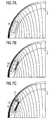
- Fig. 7 the effects of the element 12 can be seen.
- the three sub-figures show the magnetic field lines, ie the lines of the same magnetic flux, for different configurations.
- Fig. 7a the magnetic field is shown when no element 12 is present. It can be seen that the field line density on the inside of the measuring tube 2 at the lower edge of Fig. 7a is not too large, at least smaller than in the interior of the measuring tube (based on the representation of Fig. 7a: further to the right).
- FIG. 7 b shows a corresponding field line image with an element 12. It can be seen that the field line density in the region on the inside of the measuring tube 2 has greatly increased.
Landscapes
- Physics & Mathematics (AREA)
- Engineering & Computer Science (AREA)
- Power Engineering (AREA)
- Electromagnetism (AREA)
- Fluid Mechanics (AREA)
- General Physics & Mathematics (AREA)
- Measuring Volume Flow (AREA)
Description
- Die Erfindung betrifft einen magnetisch induktiven Durchflussmesser mit einem Messrohr, einer Elektrodenanordnung mit Elektroden, die auf einander gegenüberliegenden Seiten des Messrohres quer zu einer Durchflussrichtung durch das Messrohr angeordnet sind, und einer Spulenanordnung mit mindestens einer Sattelspule, deren Achse quer zur Durchflussrichtung und quer zur Elektrodenanordnung verläuft und die vier Schenkel aufweist, von denen zwei erste Schenkel parallel zur Durchflussrichtung und zwei zweite Schenkel in Umfangsrichtung des Messrohres verlaufen.
- Ein sich bewegendes elektrisch leitfähiges Fluid, das das Messrohr durchströmt, erzeugt eine Spannung zwischen den Elektroden der Elektrodenanordnung, wenn die Spulenanordnung ein Magnetfeld erzeugt. Das Magnetfeld ist dabei senkrecht zur Durchströmungsrichtung gerichtet.
- Die Spannung wird senkrecht zur Durchströmungsrichtung und senkrecht zum Magnetfeld abgenommen. Die Spannung an der Elektrodenanordnung ist dann u.a. abhängig von der Strömungsgeschwindigkeit, aus der wiederum auf die Durchflussmenge geschlossen werden kann.
- Für die Messgenauigkeit eines derartigen Durchflussmessers ist es von einer gewissen Bedeutung, dass sich das Magnetfeld über die gesamte Querschnittsfläche des Messrohres erstreckt. Eine Möglichkeit, um dies zu erreichen, ist die Verwendung eines Jochs oder Polschuhs. Die Spule erzeugt dann ein Magnetfeld, das durch den Polschuh verteilt wird und sich dann weitgehend gleichmäßig über den Querschnitt des Messrohres erstreckt.
- Allerdings erfordern derartige Polschuhe einen gewissen Bauraum. In vielen Fällen verwendet man daher Sattelspulen, deren Form an die Form des Messrohres angepasst ist. In der Regel weist die Spulenanordnung dabei zwei Sattelspulen auf. Von oben gesehen bilden die Sattelspulen im weitesten Sinn ein Viereck, von dem zwei Schenkel parallel zur Durchflussrichtung verlaufen. Die beiden anderen Schenkel folgen der Wölbung des Messrohres. Diese Schenkel können auch einen Bogen oder einen Winkel in axialer Richtung aufweisen, so dass die Sattelspule in der Draufsicht einem Sechseck ähnelt, also wie ein Diamant aussieht. Auch mit derartigen Sattelspulen lassen sich weitgehend zufriedenstellende Ergebnisse erreichen.
- Probleme treten allerdings dann auf, wenn der Durchmesser des Messrohres verkleinert werden soll. Insbesondere ab Durchmessern von beispielsweise unter 50 mm ergeben sich in erhöhtem Maße Messfehler. Man führt dies darauf zurück, dass man die Sattelspulen nicht weit genug in Umfangsrichtung um das Messrohr herum erstrecken kann. Die Elektroden der Elektrodenanordnung benötigen nämlich einen gewissen Bauraum. In der Regel weisen sie auch noch ein kleines Anschlussgehäuse auf. Die achsparallelen ersten Schenkel der Sattelspulen müssen diesen Bauraum frei lassen. Dies hat zur Folge, dass sich das Magnetfeld nicht weit genug bis zu den Elektroden hin erstreckt. Dies führt, wie oben ausgeführt, zu Messungenauigkeiten oder -fehlern.
- Der Erfindung liegt die Aufgabe zugrunde, die Messgenauigkeit bei einem Messrohr mit kleinerem Durchmesser zu verbessern.
- Aus JP07139980 ist ein magnetisch induktiver Durchflussmesser bekannt, in welchem die Messgenauigkeit durch Benutzung von einem ferromagnetischen Streifen zwischen der spule und dem Rohr verbessert ist.
- Diese Aufgabe wird bei einem magnetisch induktiven Durchflussmesser der eingangs genannten Art dadurch gelöst, dass zwischen jedem ersten Schenkel und dem Messrohr jeweils ein magnetisch leitendes Element angeordnet ist, das einen ersten Teil des magnetischen Flusses aufnimmt, wobei ein zweiter Teil des magnetischen Flusses aus einem von der Sattelspule umgebenen Bereich am Element vorbei tritt.
- Mit dem magnetisch leitenden Element wird die Richtung des Magnetfeldes geändert und zwar in Richtung der Elektrode. Das Magnetfeld füllt dann den Querschnitt des Messrohres besser aus. Das Messsignal, das an der Elektrodenanordnung abgenommen werden kann, steigt dann, wie gewünscht, an. Allerdings erreicht man diese Verbesserung des Messergebnisses dadurch, dass man nur einen Teil des magnetischen Flusses ablenkt. Der größte Teil des magnetischen Flusses in dem Bereich, der von der Sattelspule umgeben ist, bleibt nach wie vor ungestört, d. h. er kann sich ohne Beeinflussung durch einen Polschuh oder ein anderes flussverteilendes Element im Querschnitt des Messrohres ausbreiten. Vorteilhaft ist dabei vor allem, dass sich unerwünschte Streuungen, die sich am Rand eines Polschuhs ergeben können, praktisch nicht ausbilden. Hinzu kommt, dass die Bauhöhe der Sattelspule durch das Hinzufügen des magnetisch leitfähigen Elements praktisch nicht nennenswert vergrößert wird. Das magnetisch leitende Element kann als relativ dünner Streifen ausgebildet sein, der in einen Spalt hineinpasst, der zwischen der Sattelspule und dem Messrohr in der Regel ohnehin vorhanden ist. Es ist vorzugsweise in dem Bereich in Axialrichtung des Messrohres angeordnet, in dem auch die Elektroden angeordnet sind.
- Vorzugsweise geht das Element von einem Bereich am Innenrand des ersten Schenkels aus und endet zwischen dem ersten Schenkel und dem Messrohr. Der Bereich, der von der Sattelspule umschlossen wird, d. h. das sich parallel zur Achse der Sattelspule erstreckende Magnetfeld, wird durch das Element praktisch nicht gestört. Das Element ist aber in der Lage, einen Teil des Magnetflusses so umzuleiten, dass sich das Magnetfeld in die Nähe der Elektroden der Elektrodenanordnung erstreckt. Man erreicht also nennenswerte Vorteile, ohne größere Nachteile in Kauf nehmen zu müssen.
- Bevorzugterweise weist das Element einen abgewinkelten Abschnitt auf, der von innen am ersten Schenkel anliegt. Innen ist dabei die Seite, die dem anderen ersten Schenkel gegenüberliegt. Innen befindet sich also im Inneren eines Umlaufs, den die Windungen der Sattelspule ausführen. Mit dem Abschnitt wird eine automatische Positionierung des Elements relativ einfach. Das Element wird einfach "bis zum Anschlag" in den Raum zwischen dem Messrohr und der Spule, genauer gesagt dem ersten Schenkel der Spule, eingeschoben. Danach ist das Element lagerichtig angeordnet.
- Hierbei kann der Abschnitt am Schenkel oder am Messrohr befestigt sein. Die Befestigung kann beispielsweise durch Kleben erfolgen, insbesondere durch ein doppeltklebendes Klebeband. Der Abschnitt dient dann also zur Positionierung des Elements in mehrere Richtungen. Einmal wird eine Verlagerung des Elements in Umfangsrichtung vermieden. Auch eine Verlagerung des Elements in axialer Richtung wird durch eine Klebe-Befestigung zuverlässig unterbunden.
- Bevorzugterweise ist das Element U-förmig mit zwei Armen ausgebildet und auf den ersten Schenkel von innen aufgesteckt. Das Element ist also als "Clip" ausgebildet. Ein Arm des Clips hat dabei die eigentliche magnetisch leitende Funktion, die die Richtung des Feldes ändert. Die Basis des U und der dem erstgenannten Arm gegenüberliegende Arm dienen dann im Prinzip nur zum Festhalten des Elements am ersten Schenkel der Sattelspule.
- Hierbei ist besonders bevorzugt, dass die Arme aufeinander zu vorgespannt sind. Der Clip hat dann eine Federwirkung. Durch die Federwirkung der Arme wird der Clip besonders gut am ersten Schenkel der Sattelspule festgehalten.
- Bevorzugterweise ist der Arm zwischen dem ersten Schenkel und dem Messrohr quer zur Durchflussrichtung länger als der andere Arm. Wie oben ausgeführt, dient der andere Arm hauptsächlich dazu, das Element am ersten Schenkel der Sattelspule festzuhalten. Dies lässt sich auch durch eine geometrisch kleinere Ausbildung zuverlässig erreichen. Durch diese Ausbildung wird also Material gespart.
- Vorzugsweise erstreckt sich das Element über die Länge des ersten Schenkels in Durchflussrichtung. Damit wird über die gesamte axiale Länge der Sattelspule die gewünschte Umleitung des magnetischen Feldes in Richtung auf den Teil der Wand des Messrohres bewirkt, in der die Elektrode angeordnet ist.
- Vorzugsweise weist das Element in Durchflussrichtung zwischen seinen Enden eine Ausnehmung auf. Es hat sich herausgestellt, dass auch mit einer derartigen Ausnehmung ein zufriedenstellendes Messergebnis erreicht wird. Das Magnetfeld sieht dann etwas anders aus. Es wird in Axialrichtung, d. h. in Durchflussrichtung, gespreizt. Dies spielt aber keine größere Rolle, da es hauptsächlich darauf ankommt, dass das Magnetfeld im Bereich der Elektrodenanordnung die gewünschte Verteilung hat.
- Bevorzugterweise weist das Element eine wellenförmige Oberfläche auf. Es kann auch selbst gewellt sein. Mit der wellenförmigen Oberfläche ist es möglich, das Element zwischen dem ersten Schenkel der Sattelspule und dem Messrohr zu befestigen.
- Vorzugsweise ist das Element durch weichmagnetisches Eisen gebildet. Weichmagnetisches Eisen hat hervorragende Eigenschaften beim Leiten von Magnetfeldern.
- Alternativ dazu kann das Element durch einen magnetisch leitenden Kunststoff gebildet sein. Dies lässt sich beispielsweise dadurch realisieren, dass man einen Streifen aus einem magnetisch leitenden Kleber bildet. Hierzu wird Magnetpulver oder Eisenpulver mit Kleber gemischt und dieser Kleber wird positionsgenau zwischen dem ersten Schenkel der Sattelspule und dem Messrohr angeordnet.
- Vorzugsweise ist das Element zusammen mit dem Messrohr vergossen. Mit diesem Gießvorgang kann das Element in das Messrohr eingebettet werden. Danach wird die Sattelspule auf dem Messrohr angebracht, z. B. festgeklebt, und die so gebildete Kombination in ein äußeres Rohr eingeschoben. Danach erfolgt ein zweites Vergießen. Wenn die erwähnten Teile in die Gussmasse eingebettet sind und die Gussmasse ausgehärtet ist, dann sind alle Teile richtig zueinander positioniert und es besteht keine Gefahr, dass diese Positionierung durch äußere Einflüsse verändert wird.
- Bevorzugterweise hat das Element eine Erstreckung quer zur Durchflussrichtung, bei der ein Messfehler einen Minimalwert aufweist. Das Element hat, wie oben erwähnt, die Aufgabe, das Magnetfeld, das die Sattelspule erzeugt, näher an die Elektrode heranzuführen. Hierbei gibt es einen Punkt mit maximaler magnetischer Flussdichte. Dieser Punkt ist mit der Länge des Elements quer zur Durchflussrichtung, genauer gesagt in Umfangsrichtung des Messrohres oder in Tangentialrichtung des Messrohres, verlagerbar. Je länger das Element ist, desto näher kommt der Punkt an die Elektrode, und bei einer korrekten Länge ist der Messfehler fast aufgehoben. Die Länge des Elements bestimmt die Linearität des Messresultats und die "beste" Länge ist somit die Länge, die den kleinsten Linearitätsfehler zur Folge hat. Wird die Länge hingegen wieder zu groß gewählt, dann ergeben sich andere Fehler. Nur ein kleiner Teil des magnetischen Flusses der ganzen Sattelspule läuft durch das Element, aber dieser kleine Teil wird von dem Element örtlich konzentriert.
- Die Erfindung wird im Folgenden anhand von bevorzugten Ausführungsbeispielen in Verbindung mit der Zeichnung näher beschrieben. Hierin zeigen:
- Fig. 1
- eine schematische Darstellung zur Erläuterung des Funktionsprinzips eines magnetisch induktiven Durchflussmessers,
- Fig. 2
- einen Durchflussmesser schematisch im Teilschnitt,
- Fig. 3
- eine Teilansicht aus Fig. 2,
- Fig. 4
- eine geänderte Ausführungsform in entsprechender Ansicht nach Fig. 3,
- Fig. 5
- eine dritte Ausführungsform eines magnetisch leitenden Elements,
- Fig. 6
- eine schematische Darstellung zur Erläuterung des Fehlerverhaltens und
- Fig. 7
- verschiedene Feldverläufe.
- Fig. 1 zeigt einen magnetisch induktiven Durchflussmesser 1 mit einem Messrohr 2, das von einem Fluid, also einem Gas oder einer Flüssigkeit, in Axialrichtung, d. h. in einer Durchflussrichtung 3, durchflossen werden kann. Auf dem Messrohr 2 sind zwei einander gegenüberliegende Sattelspulen 4 angeordnet, die so mit Strom beaufschlagt werden, dass sie ein Magnetfeld 5 erzeugen, das durch einen Pfeil symbolisiert ist. Das Magnetfeld 5 verläuft im Wesentlichen senkrecht zur Durchflussrichtung 3. Das Magnetfeld 5 ist natürlich nicht auf einer Linie konzentriert, sondern erstreckt sich im Idealfall über den gesamten Querschnitt des Messrohres 2.
- Eine Elektrodenanordnung, von der eine Elektrode 6 im Messrohr 2 dargestellt ist, ist so angeordnet, dass eine Spannung 7, die durch einen Pfeil symbolisiert ist, im Wesentlichen senkrecht zum Magnetfeld 5 und im Wesentlichen senkrecht zur Durchflussrichtung 3 abgenommen werden kann, wenn sich das Fluid bewegt. Die Größe der Spannung 7 ist ein Maß für die Durchflussgeschwindigkeit und damit ein Maß für den Durchfluss des Fluids durch das Messrohr 2.
- Die Sattelspulen 4 sind in der Draufsicht (also in einer Ansicht aus einer Richtung parallel zum Magnetfeld 5) im Wesentlichen rechteckförmig ausgebildet. Hierbei gibt es zwei erste Schenkel 8, die parallel zur Durchflussrichtung 3 verlaufen, und zwei zweite Schenkel 9, die an die Krümmung des Messrohrs 2 angepasst sind. Dadurch ist es möglich, die Sattelspulen 4 relativ dicht an das Messrohr 2 anzunähern und trotzdem ein Magnetfeld zu erzeugen. Ein Polschuh oder ein Joch ist hierzu jedoch nicht erforderlich. Die ersten und die zweiten Schenkel können geradlinig verlaufen oder mehrere geradlinig verlaufende Abschnitte aufweisen, die gegenseitig Winkel einschließen.
- Fig. 2 zeigt nun wesentliche Teile des Durchflussmessers 1 in einer vergrößerten Ausschnittsdarstellung. Die Darstellung der Fig. 2 zeigt einen Schnitt in der Ebene, in der die Elektroden 6 angeordnet sind.
- Die Elektroden 6 sind von einem schematisch dargestellten Anschlussgehäuse 10 umgeben. Dieses Anschlussgehäuse 10 verhindert, dass sich die ersten Schenkel 8 der Sattelspulen 4 der Elektrode 6 nähern können, d. h. es verbleibt ein deutlicher Abstand zwischen den ersten Schenkeln 8 der Sattelspule 4 und der Elektrode 6. Dies hat zur Folge, dass sich ein Magnetfeld ausbildet, das sich zur Elektrode 6 hin stark abschwächt. Um dies zu verdeutlichen, ist eine Feldlinie 11 dieses Magnetfelds gestrichelt eingezeichnet. Diese Feldlinie 11 hat einen relativ großen Abstand zur Elektrode 6.
- Um dieses Problem zu beseitigen, ist ein magnetisch leitendes Element 12 in einen Spalt 13 zwischen dem ersten Schenkel 8 der Sattelspule 4 und dem Messrohr 2 eingefügt worden. Dieses Element 12 hat eine Länge L in Umfangsrichtung oder quer zur Durchflussrichtung 3, d. h. es geht vom Innenrand 14 des ersten Schenkels 8 aus und erstreckt sich über die Länge L unter dem ersten Schenkel 8 hindurch und endet zwischen dem ersten Schenkel 8 und dem Messrohr.
- Das magnetisch leitfähige Element 12 verändert nun das Magnetfeld so, dass es näher an die Elektrode 6 heranrückt. Hierzu ist eine Feldlinie 15 dargestellt, an der das Magnetfeld die gleiche Feldstärke hat wie ohne das Element 12 an der zuvor diskutierten Feldlinie 11. Ein Schnittpunkt P der Feldlinie 15 mit dem Messrohr 2 wird weiter in Richtung auf die Elektrode 6 verschoben. Das Messsignal steigt dann, wie erwünscht, an. Durch eine geeignete Länge L, d. h. die Erstreckung des Elements in Umfangs- oder Tangentialrichtung des Messrohres 2, lässt sich ein Punkt P mit maximalem magnetischen Fluss finden. Dieser Punkt ist mit der Länge L des Elements 12 bewegbar. Je länger die Länge L ist, desto näher kommt der Punkt P an die Elektrode 6.
- Nur ein kleiner Teil des magnetischen Flusses einer ganzen Sattelspule 4 läuft durch das Element 12, aber dieser Teil des magnetischen Flusses wird von dem Element örtlich konzentriert. Im Gegensatz hierzu wird im Stand der Technik bei Verwendung eines Polschuhs oder Jochs der gesamte Fluss durch den Polschuh geleitet.
- Das Messrohr 2 ist aus einem magnetisch nicht leitenden Material, beispielsweise einem Kunststoff, gebildet. Das Magnetfeld schließt sich durch ein äußeres Rohr 16, das das Messrohr 2 und die Sattelspulen 4 sowie das Anschlussgehäuse 10 der Elektroden 6 umgibt. Dieses Rohr 16 ist aus Gründen der Übersichtlichkeit in Fig. 1 nicht dargestellt. Es ist aus einem magnetisch leitenden Material gebildet, beispielsweise aus Weicheisen.
- In den Fig. 3 bis 5 sind nun verschiedene Möglichkeiten gezeigt, wie das Element 12 ausgebildet sein kann. Gleiche und einander entsprechende Teile wie in Fig. 2 sind mit den gleichen Bezugszeichen versehen. Das äußere Rohr 16 ist weggelassen.
- In Fig. 3 hat das Element 12 einen abgewinkelten Abschnitt 17 mit einer Breite D. Dieser Abschnitt 17 hat praktisch keine magnetische Funktion. Er dient lediglich dazu, dass das Element 12 am ersten Schenkel 8 festgelegt werden kann und zwar an seiner Innenseite 14. Die Innenseite 14 ist, wie aus Fig. 1 zu erkennen ist, die Seite des ersten Schenkels 8, die von der Sattelspule 4 umgeben ist, also dem anderen ersten Schenkel 8, der in Fig. 1 nicht zu erkennen ist, gegenüberliegt.
- Man kann den Abschnitt 17 einfach an dem ersten Schenkel 8 der Sattelspule zur Anlage bringen. Man kann aber auch einen Kleber 18 vorsehen, der zwischen dem Abschnitt 17 und dem ersten Schenkel 8 angebracht wird und den ersten Abschnitt 17 am ersten Schenkel 8 festklebt. Der Kleber 18 kann beispielsweise in der Form eines doppeltklebenden Klebestreifens ausgebildet sein. Alternativ kann der Kleber zwischen dem Messrohr 2 und dem Element 12 bzw. zwischen dem Element 12 und dem Schenkel 8 angebracht werden.
- In Durchflussrichtung erstreckt sich das Element 12 vorzugsweise über die gesamte axiale Länge des ersten Schenkels 8, d. h. über die Länge zwischen den beiden zweiten Schenkeln 9.
- Fig. 4 zeigt eine Ausführungsform, bei der das Element 12 als Clip ausgebildet ist. Es ist zu diesem Zweck U-förmig ausgebildet mit dem Abschnitt 17 als Basis und zwei Armen 19, 20, wobei der dem Messrohr 2 benachbarte Arm 20 länger ist als der Arm 19 auf der gegenüberliegenden Seite des ersten Schenkels 8. Der Arm 19 hat ebenfalls praktisch keine magnetische Funktion. Er dient lediglich dazu, das Element 12 durch Klemmwirkung auf dem ersten Schenkel 8 der Sattelspule 4 festzuhalten. Hierzu ist das Element 12 vorgespannt, d. h. der Arm 19 schließt mit dem Abschnitt 17 einen Winkel α ein, der etwas kleiner ist als der Winkel an der entsprechenden Kante des ersten Schenkels 8. In gleicher Weise schließt der Arm 20 mit dem Abschnitt 17 einen Winkel α' ein, der ebenfalls etwas kleiner ist, als dies durch die Geometrie des Schenkels 8 vorgegeben ist. Dadurch wird eine Eigenspannung erzeugt, die das Element 12 sicher auf dem ersten Schenkel 8 hält.
- Das Element 12 wird also als Clip mit einer kleinen Kraft auf den ersten Schenkel 8 aufgeschoben. Man kann später den Raum zwischen dem äußeren Rohr 16 und dem Messrohr 2 mit einer Gussmasse ausfüllen, so dass die Sattelspulen 4, die Elemente 12 und die Leitungen sowie das Anschlussgehäuse 10 und die Elektrode 6 mechanisch befestigt sind.
- Das Element 12 muss nicht in mechanischem Kontakt mit der Sattelspule 4 stehen. Es genügt, wenn es zwischen der Sattelspule 4 und dem Messrohr 2 angebracht ist.
- Selbstverständlich sind derartige Elemente 12 zwischen allen vier ersten Schenkeln 8 der beiden Sattelspulen 4 und dem Messrohr 2 angeordnet.
- Eine nicht näher dargestellte Variante besteht darin, dass das Element aus einem Streifen aus magnetisch leitendem Kleber oder Kunststoff gebildet ist. Hierzu wird beispielsweise Magnetpulver oder Weicheisenpulver mit einem Klebstoff gemischt und dieser Klebstoff wird positionsgenau zwischen dem ersten Schenkel 8 und dem Messrohr 2 angebracht.
- Vorzugsweise ist jedoch das Element 12 aus weichmagnetischem Eisen. Weichmagnetisches Eisen leitet ein Magnetfeld, wie dies an sich bekannt ist.
- Fig. 5 zeigt eine weitere Ausgestaltung, bei der ein Element 12, das ansonsten im Wesentlichen dem der Fig. 4 entspricht, eine Ausnehmung 21 zwischen seinen in Durchflussrichtung 3 liegenden Enden 22, 23 aufweist. Dadurch entstehen magnetisch leitende Streifen 24, 25, die das Magnetfeld zu einem Verteilerstreifen 26 führen. Mit dieser Ausgestaltung wird ein Magnetfeld erzeugt, das etwas um den Punkt P gespreizt ist.
- In nicht näher dargestellter Weise kann auch vorgesehen sein, dass die Oberfläche des Elements 12 gewellt ist oder das Element 12 selbst gewellt ist. Die Struktur könnte beispielsweise sinusförmig sein.
- Fig. 6 zeigt schematisch die Auswirkungen des Elements 12. Eine Kurve 27 stellt einen relativen Fehler X über den Durchfluss F dar. Es ist zu erkennen, dass bei kleinen Durchflussraten der Messfehler stark ansteigt. Mit anderen Worten entsteht aufgrund eines zu geringen Magnetfelds im Bereich der Elektroden 6 ein geringes Messsignal und ein erhöhtes Signal/Rausch-Verhältnis.
- Eine Kurve 28 stellt den Fehlerverlauf für ein Element 12 mit optimaler Länge L dar. Es ist zu erkennen, dass der Fehler auch bei kleinen Durchflussraten relativ klein bleibt.
- Eine Kurve 29 stellt die Situation dar, bei der zwar ein Element 12 verwendet wird, die Länge L dieses Elements aber zu groß ist. Der Fehler bleibt zwar kleiner als ohne Element 12. Wenn die Länge L zu groß ist, ist das Messergebnis aber nicht optimal.
- In Fig. 7 sind die Auswirkungen des Elements 12 erkennbar. Die drei Teilfiguren zeigen die magnetischen Feldlinien, also die Linien gleichen magnetischen Flusses, für unterschiedliche Ausgestaltungen. In Fig. 7a ist das magnetische Feld dargestellt, wenn kein Element 12 vorhanden ist. Es ist erkennbar, dass die Feldliniendichte auf der Innenseite des Messrohres 2 an der Unterkante der Fig. 7a nicht allzu groß ist, jedenfalls kleiner als im Innern des Messrohrs (bezogen auf die Darstellung der Fig. 7a: weiter nach rechts).
- Fig. 7b zeigt ein entsprechendes Feldlinienbild mit einem Element 12. Es ist zu erkennen, dass die Feldliniendichte in dem Bereich auf der Innenseite des Messrohres 2 stark zugenommen hat.
- Noch deutlicher wird die Situation, wenn ein Element 12 mit einem Abschnitt 17 verwendet wird. Die Feldliniendichte ist nun in dem Bereich an der Innenseite des Messrohres 2 unterhalb des ersten Schenkels 8 größer geworden. Dies ist in Fig. 7c dargestellt.
Claims (14)
- Magnetisch induktiver Durchflussmesser mit einem Messrohr, einer Elektrodenanordnung mit Elektroden, die auf einander gegenüberliegenden Seiten des Messrohrs quer zu einer Durchflussrichtung durch das Messrohr angeordnet sind, und einer Spulenanordnung mit mindestens einer Sattelspule, deren Achse quer zur Durchflussrichtung und quer zur Elektrodenanordnung verläuft und die vier Schenkel aufweist, von denen zwei erste Schenkel parallel zur Durchflussrichtung und zwei zweite Schenkel in Umfangsrichtung des Messrohres verlaufen, dadurch gekennzeichnet, dass zwischen jedem ersten Schenkel (8) und dem Messrohr (2) jeweils ein magnetisch leitendes Element (12) angeordnet ist, das einen ersten Teil des magnetischen Flusses aufnimmt, wobei ein zweiter Teil des magnetischen Flusses aus einem von der Sattelspule (4) umgebenen Bereich am Element (12) vorbei tritt.
- Durchflussmesser nach Anspruch 1, dadurch gekennzeichnet, dass das Element (12) von einem Bereich am Innenrand (14) des ersten Schenkels (8) ausgeht und zwischen dem ersten Schenkel (8) und dem Messrohr (2) endet.
- Durchflussmesser nach Anspruch 1 oder 2, dadurch gekennzeichnet, dass das Element (12) einen abgewinkelten Abschnitt (17) aufweist, der von innen am ersten Schenkel (8) anliegt.
- Durchflussmesser nach Anspruch 3, dadurch gekennzeichnet, dass der Abschnitt (17) am Schenkel (8) oder am Messrohr (2) befestigt sein kann.
- Durchflussmesser nach einem der Ansprüche 1 bis 4, dadurch gekennzeichnet, dass das Element (12) U-förmig mit zwei Armen (19, 20) ausgebildet und auf den ersten Schenkel (8) von innen aufgesteckt ist.
- Durchflussmesser nach Anspruch 5, dadurch gekennzeichnet, dass die Arme (19, 20) aufeinander zu vorgespannt sind.
- Durchflussmesser nach Anspruch 5 oder 6, dadurch gekennzeichnet, dass der Arm (20) zwischen dem ersten Schenkel (8) und dem Messrohr (2) quer zur Durchflussrichtung (3) länger als der andere Arm (19) ist.
- Durchflussmesser nach einem der Ansprüche 1 bis 7, dadurch gekennzeichnet, dass sich das Element (12) über die Länge des ersten Schenkels (8) in Durchflussrichtung (3) erstreckt.
- Durchflussmesser nach einem der Ansprüche 1 bis 8, dadurch gekennzeichnet, dass das Element (12) in Durchflussrichtung (3) zwischen seinen Enden (22, 23) eine Ausnehmung (21) aufweist.
- Durchflussmesser nach einem der Ansprüche 1 bis 9, dadurch gekennzeichnet, dass das Element (12) eine wellenförmige Oberfläche aufweist.
- Durchflussmesser nach einem der Ansprüche 1 bis 10, dadurch gekennzeichnet, dass das Element (12) durch weichmagnetisches Eisen gebildet ist.
- Durchflussmesser nach einem der Ansprüche 1 bis 10, dadurch gekennzeichnet, dass das Element (12) durch einen magnetisch leitenden Kunststoff gebildet ist.
- Durchflussmesser nach einem der Ansprüche 1 bis 12, dadurch gekennzeichnet, dass das Element (12) zusammen mit dem Messrohr (2) vergossen ist.
- Durchflussmesser nach einem der Ansprüche 1 bis 13, dadurch gekennzeichnet, dass das Element (12) eine Erstreckung quer zur Durchflussrichtung (3) hat, bei der ein Messfehler einen Minimalwert aufweist.
Applications Claiming Priority (3)
| Application Number | Priority Date | Filing Date | Title |
|---|---|---|---|
| DE10252041 | 2002-11-06 | ||
| DE2002152041 DE10252041B4 (de) | 2002-11-06 | 2002-11-06 | Magnetisch induktiver Durchflußmesser |
| PCT/DE2003/003670 WO2004042328A2 (de) | 2002-11-06 | 2003-11-06 | Magnetisch induktiver durchflussmesser |
Publications (2)
| Publication Number | Publication Date |
|---|---|
| EP1558898A2 EP1558898A2 (de) | 2005-08-03 |
| EP1558898B1 true EP1558898B1 (de) | 2007-02-28 |
Family
ID=32185367
Family Applications (1)
| Application Number | Title | Priority Date | Filing Date |
|---|---|---|---|
| EP03782092A Expired - Lifetime EP1558898B1 (de) | 2002-11-06 | 2003-11-06 | Magnetisch induktiver durchflussmesser |
Country Status (3)
| Country | Link |
|---|---|
| EP (1) | EP1558898B1 (de) |
| DE (2) | DE10252041B4 (de) |
| WO (1) | WO2004042328A2 (de) |
Cited By (1)
| Publication number | Priority date | Publication date | Assignee | Title |
|---|---|---|---|---|
| DE102014212802A1 (de) | 2014-07-02 | 2016-01-07 | Siemens Aktiengesellschaft | Magnetisch induktiver Durchflussmesser |
Families Citing this family (3)
| Publication number | Priority date | Publication date | Assignee | Title |
|---|---|---|---|---|
| DE102004063020B4 (de) * | 2004-12-22 | 2007-10-18 | Krohne Ag | Magnetisch-induktives Durchflußmeßgerät |
| US7296483B2 (en) | 2005-12-09 | 2007-11-20 | Krohne Ag | Magnetoinductive flowmeter with detachable components |
| GB2440963B (en) * | 2006-08-18 | 2011-06-08 | Abb Ltd | Flow meter |
Family Cites Families (6)
| Publication number | Priority date | Publication date | Assignee | Title |
|---|---|---|---|---|
| US3681986A (en) * | 1971-04-30 | 1972-08-08 | Nat Res Dev | Fluid flow meters |
| JPS58155315A (ja) * | 1982-03-12 | 1983-09-16 | Toshiba Corp | 電磁流量計検出器 |
| JPS58213215A (ja) * | 1982-06-04 | 1983-12-12 | Yamatake Honeywell Co Ltd | 電磁流量計 |
| DE3501768A1 (de) * | 1985-01-21 | 1986-07-24 | Danfoss A/S, Nordborg | Elektromagnetischer durchflussmesser |
| JPH07139980A (ja) * | 1993-11-18 | 1995-06-02 | Fuji Electric Co Ltd | 電磁流量計 |
| DE20217213U1 (de) * | 2002-11-06 | 2003-01-09 | Danfoss A/S, Nordborg | Magnetisch induktiver Durchflußmesser |
-
2002
- 2002-11-06 DE DE2002152041 patent/DE10252041B4/de not_active Expired - Fee Related
-
2003
- 2003-11-06 WO PCT/DE2003/003670 patent/WO2004042328A2/de not_active Ceased
- 2003-11-06 DE DE50306693T patent/DE50306693D1/de not_active Expired - Lifetime
- 2003-11-06 EP EP03782092A patent/EP1558898B1/de not_active Expired - Lifetime
Cited By (1)
| Publication number | Priority date | Publication date | Assignee | Title |
|---|---|---|---|---|
| DE102014212802A1 (de) | 2014-07-02 | 2016-01-07 | Siemens Aktiengesellschaft | Magnetisch induktiver Durchflussmesser |
Also Published As
| Publication number | Publication date |
|---|---|
| DE50306693D1 (de) | 2007-04-12 |
| WO2004042328A2 (de) | 2004-05-21 |
| DE10252041A1 (de) | 2004-05-27 |
| EP1558898A2 (de) | 2005-08-03 |
| DE10252041B4 (de) | 2005-02-17 |
| WO2004042328A3 (de) | 2004-07-08 |
Similar Documents
| Publication | Publication Date | Title |
|---|---|---|
| DE3523593C2 (de) | ||
| EP3723196B1 (de) | Antenne | |
| EP1558898B1 (de) | Magnetisch induktiver durchflussmesser | |
| EP1592950A1 (de) | Montagepaket für die herstellung eines magnetisch-induktiven durchflussmessers | |
| DE1915324A1 (de) | Stroemungsmesser | |
| DE3829059C2 (de) | ||
| EP0073002B1 (de) | Sperrmagnetauslöser | |
| EP0797078B1 (de) | Induktiver Drehwinkelsensor | |
| DE20217213U1 (de) | Magnetisch induktiver Durchflußmesser | |
| DE2944775C2 (de) | Ablenkjoch für eine Kathodenstrahlröhre | |
| DE2701230C3 (de) | Elektromagnetisches Relais und Verfahren zu dessen Justierung | |
| DE2608114A1 (de) | Temperaturabhaengiger zungenschalter | |
| DE102008033738A1 (de) | Wippschalter | |
| DE69109709T2 (de) | Spulenanordnung. | |
| DE3829058C2 (de) | ||
| DE2916500A1 (de) | Endschalter fuer arbeitszylinder | |
| DE2719230C3 (de) | Magnetisches Relais | |
| DE3110251A1 (de) | "elektromagnet" | |
| DE1614754B2 (de) | Schutzrohrankerkontakt | |
| AT281973B (de) | Haftrelais | |
| DE2626866C2 (de) | Induktiver Geber | |
| DE2908160C2 (de) | Drehspulinstrument | |
| DE102011002739A1 (de) | Verfahren zum Herstellen einer Sensorvorrichtung, Verfahren zum Herstellen einer Sensorbaugruppe, Sensorvorrichtung und Sensorbaugruppe | |
| DE2605642A1 (de) | Vorrichtung zum ueberwachen der stroemungsmenge von fluessigen oder gasfoermigen medien in leitungen | |
| DE102016214158B4 (de) | Drehspulenanordnung |
Legal Events
| Date | Code | Title | Description |
|---|---|---|---|
| PUAI | Public reference made under article 153(3) epc to a published international application that has entered the european phase |
Free format text: ORIGINAL CODE: 0009012 |
|
| 17P | Request for examination filed |
Effective date: 20050428 |
|
| AK | Designated contracting states |
Kind code of ref document: A2 Designated state(s): AT BE BG CH CY CZ DE DK EE ES FI FR GB GR HU IE IT LI LU MC NL PT RO SE SI SK TR |
|
| AX | Request for extension of the european patent |
Extension state: AL LT LV MK |
|
| DAX | Request for extension of the european patent (deleted) | ||
| RBV | Designated contracting states (corrected) |
Designated state(s): DE FR GB |
|
| GRAP | Despatch of communication of intention to grant a patent |
Free format text: ORIGINAL CODE: EPIDOSNIGR1 |
|
| RIN1 | Information on inventor provided before grant (corrected) |
Inventor name: NIELSEN, S REN Inventor name: JENSEN, FINN |
|
| GRAS | Grant fee paid |
Free format text: ORIGINAL CODE: EPIDOSNIGR3 |
|
| GRAA | (expected) grant |
Free format text: ORIGINAL CODE: 0009210 |
|
| AK | Designated contracting states |
Kind code of ref document: B1 Designated state(s): DE FR GB |
|
| REG | Reference to a national code |
Ref country code: GB Ref legal event code: FG4D Free format text: NOT ENGLISH |
|
| REF | Corresponds to: |
Ref document number: 50306693 Country of ref document: DE Date of ref document: 20070412 Kind code of ref document: P |
|
| GBT | Gb: translation of ep patent filed (gb section 77(6)(a)/1977) |
Effective date: 20070523 |
|
| ET | Fr: translation filed | ||
| PLBE | No opposition filed within time limit |
Free format text: ORIGINAL CODE: 0009261 |
|
| STAA | Information on the status of an ep patent application or granted ep patent |
Free format text: STATUS: NO OPPOSITION FILED WITHIN TIME LIMIT |
|
| 26N | No opposition filed |
Effective date: 20071129 |
|
| PGFP | Annual fee paid to national office [announced via postgrant information from national office to epo] |
Ref country code: GB Payment date: 20121115 Year of fee payment: 10 |
|
| PGFP | Annual fee paid to national office [announced via postgrant information from national office to epo] |
Ref country code: FR Payment date: 20121214 Year of fee payment: 10 |
|
| PGFP | Annual fee paid to national office [announced via postgrant information from national office to epo] |
Ref country code: DE Payment date: 20130118 Year of fee payment: 10 |
|
| GBPC | Gb: european patent ceased through non-payment of renewal fee |
Effective date: 20131106 |
|
| REG | Reference to a national code |
Ref country code: FR Ref legal event code: ST Effective date: 20140731 |
|
| PG25 | Lapsed in a contracting state [announced via postgrant information from national office to epo] |
Ref country code: DE Free format text: LAPSE BECAUSE OF NON-PAYMENT OF DUE FEES Effective date: 20140603 |
|
| REG | Reference to a national code |
Ref country code: DE Ref legal event code: R119 Ref document number: 50306693 Country of ref document: DE Effective date: 20140603 |
|
| PG25 | Lapsed in a contracting state [announced via postgrant information from national office to epo] |
Ref country code: FR Free format text: LAPSE BECAUSE OF NON-PAYMENT OF DUE FEES Effective date: 20131202 Ref country code: GB Free format text: LAPSE BECAUSE OF NON-PAYMENT OF DUE FEES Effective date: 20131106 |