EP1558498B1 - Contenant pour objets plats en position debout - Google Patents
Contenant pour objets plats en position debout Download PDFInfo
- Publication number
- EP1558498B1 EP1558498B1 EP03763583A EP03763583A EP1558498B1 EP 1558498 B1 EP1558498 B1 EP 1558498B1 EP 03763583 A EP03763583 A EP 03763583A EP 03763583 A EP03763583 A EP 03763583A EP 1558498 B1 EP1558498 B1 EP 1558498B1
- Authority
- EP
- European Patent Office
- Prior art keywords
- container
- longitudinal walls
- material web
- container according
- walls
- Prior art date
- Legal status (The legal status is an assumption and is not a legal conclusion. Google has not performed a legal analysis and makes no representation as to the accuracy of the status listed.)
- Expired - Lifetime
Links
- 239000000463 material Substances 0.000 claims description 22
- 230000007246 mechanism Effects 0.000 claims description 7
- 238000000034 method Methods 0.000 description 2
- 239000002689 soil Substances 0.000 description 1
- 239000003351 stiffener Substances 0.000 description 1
Images


Classifications
-
- B—PERFORMING OPERATIONS; TRANSPORTING
- B07—SEPARATING SOLIDS FROM SOLIDS; SORTING
- B07C—POSTAL SORTING; SORTING INDIVIDUAL ARTICLES, OR BULK MATERIAL FIT TO BE SORTED PIECE-MEAL, e.g. BY PICKING
- B07C3/00—Sorting according to destination
- B07C3/008—Means for collecting objects, e.g. containers for sorted mail items
-
- B—PERFORMING OPERATIONS; TRANSPORTING
- B65—CONVEYING; PACKING; STORING; HANDLING THIN OR FILAMENTARY MATERIAL
- B65D—CONTAINERS FOR STORAGE OR TRANSPORT OF ARTICLES OR MATERIALS, e.g. BAGS, BARRELS, BOTTLES, BOXES, CANS, CARTONS, CRATES, DRUMS, JARS, TANKS, HOPPERS, FORWARDING CONTAINERS; ACCESSORIES, CLOSURES, OR FITTINGS THEREFOR; PACKAGING ELEMENTS; PACKAGES
- B65D25/00—Details of other kinds or types of rigid or semi-rigid containers
- B65D25/005—Side walls formed with an aperture or a movable portion arranged to allow removal or insertion of contents
-
- Y—GENERAL TAGGING OF NEW TECHNOLOGICAL DEVELOPMENTS; GENERAL TAGGING OF CROSS-SECTIONAL TECHNOLOGIES SPANNING OVER SEVERAL SECTIONS OF THE IPC; TECHNICAL SUBJECTS COVERED BY FORMER USPC CROSS-REFERENCE ART COLLECTIONS [XRACs] AND DIGESTS
- Y10—TECHNICAL SUBJECTS COVERED BY FORMER USPC
- Y10S—TECHNICAL SUBJECTS COVERED BY FORMER USPC CROSS-REFERENCE ART COLLECTIONS [XRACs] AND DIGESTS
- Y10S209/00—Classifying, separating, and assorting solids
- Y10S209/90—Sorting flat-type mail
Definitions
- the invention relates to a container for flat objects in a standing position according to the preamble of claim 1.
- EP 0 109 325, FR 2 621 297 describe postal containers required for this purpose. These are made of plastic (PP) and have various stiffeners to achieve a required dimensional stability. These containers are designed so that they are at the same mutual alignment and one another are aligned with each other by 180 ° about the vertical axis twisted alignment stacked.
- a corresponding container for flat objects, such as letters, in a standing position has also been described in DE 94 17 521 U1.
- a container with a designed as a roller shutter end wall, which is displaceable down into a space in the ground (DE 92 11 696 U1).
- This roller shutter solution is relatively heavy and requires a lot of space.
- the invention is therefore an object of the invention to provide a container for flat objects in a standing position, with the least one end face wall which is displaceable down into a space in the ground, which is carried out over the prior art, light and compact.
- the material web consists of a flexible thin material web, which is stretched at its ends extending perpendicular to the longitudinal walls between two rods.
- the lower rod is guided in the space in the ground and movable and the upper rod is displaceable between the bottom and upper end along the frontal boundary of the longitudinal walls.
- the rods are at their lateral ends on each container longitudinal side together in a pivotally mounted on the longitudinal wall holding mechanism, the material web holding out.
- the holding mechanism consists of rotatable levers, at whose ends directed to the container end of the upper rod is fixed. They are rotatably mounted approximately in the middle of their longitudinal direction on the lateral longitudinal walls, wherein the two axes of rotation are aligned and perpendicular to the longitudinal walls.
- the tension elements are elastic and under a bias. As a result, occurring tolerances can be compensated, so that the webs of material can be kept constantly taut.
- the lateral longitudinal walls advantageously have stops.
- the lateral longitudinal walls have outside recesses in which the lever sunk rotatably and which can be closed by external covers. This avoids that the holding mechanism is obstructed during its movement.
- the material web / s has / have a handle recess on the upper rod. This allows the upper bar to be used as a carry handle.
- a plurality of thin, flexible material webs are fastened at a distance from one another on the two rods.
- the bottom of the front side has between the webs lugs that dive into the slots between the webs and thus prevent entry of objects between the web and the bottom when opening the container.
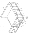
- the container has two lateral longitudinal walls 10 and two end walls.
- the front walls can be opened and closed independently. The opening is done by simply pressing down the front wall and closing by simply pulling up the front wall.
- An end wall consists of three wide, parallel, flexible thin material webs 1, which are spanned at their ends extending perpendicular to the longitudinal walls 10 between two rods 2.3.
- the upper bar 2 is designed as a handle bar. In the middle of the handle bar, the middle material web has a corresponding handle recess (12).
- the lower bar 3 is located in a space of the bottom.
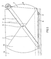
- the handle bar is on the side Ends are attached to two parallel levers 4, which are rotatably mounted on coaxial axes 5, perpendicular to the lateral longitudinal walls 10.
- the levers 4 are recessed in recesses (11) guided whose boundaries form stop surfaces 7 for the lever 4, wherein the position of the stop surfaces 7 is selected so that the handle bar in the upper position just below the upper edge of the lateral longitudinal walls 10 and is in the lower position below the bearing surface of the soil.
- the stop surfaces 7, the diameter of the handle bar and the thickness of the bottom are designed so that the handle bar is located in the area below the inner surface of the container bottom and above the outer surface of the container bottom, when the front of the container is open.
- the longitudinal walls 10 have arcuate, extending beyond the floor extensions that prevent slipping through the gap between the longitudinal wall 10 and web 1 objects.
- an elastic tension element 6 is fixed between the other end of the lever 4 and the lower rod 3 in the ground. It is deflected in each case at two rounded edges in the longitudinal wall 10 and is under a slight bias, whereby the end wall is clamped.
- the levers 4 form with the between the handle bar / upper bar 2 and the lower bar 3 spanned material webs 1 and the tension elements 6 is a "closed unit" with an approximately constant arc length, which when opening and closing the container only is subject to slight fluctuations, which are compensated by the elastic tension elements 6.
- the material webs 1, through which the end face of the container is closed, are when opening the container on the lower rod 3 by the tension elements 6 in the intermediate space pulled into the ground.
- the webs of material 1 are pulled out of the gap in the ground and back up by the handle bar. So that when opening the container no flat objects are drawn into the gap between the webs 1 and the bottom, there are 1 spaces between the parallel webs of material.
- the floor is extended in these areas by protruding lugs 8, which dive into the distances between the webs 1 and thus prevent entry of objects between web 1 and container bottom when opening the container.
- the friction between the moving elements and the container increases, whereby the force for opening and closing and the own locking force of the entire locking mechanism is increased in the open and closed positions and in possible intermediate positions. Is sufficient own locking force of the locking mechanism by friction not because z. B. act by a tilting stack of flat objects forces on the handlebar, it is advantageous to provide an additional lock. This can, for. B. in the form of spring-loaded Kugelschnappern that engage in the closed position on one or both levers 2,3, are executed.
Landscapes
- Engineering & Computer Science (AREA)
- Mechanical Engineering (AREA)
- Details Of Rigid Or Semi-Rigid Containers (AREA)
- Rigid Containers With Two Or More Constituent Elements (AREA)
- Packaging Of Annular Or Rod-Shaped Articles, Wearing Apparel, Cassettes, Or The Like (AREA)
Claims (7)
- Récipient pour des objets plats en position verticale, comportant un fond, deux parois longitudinales (10) latérales et deux parois frontales, les grands côtés des objets plats étant tournés vers les parois frontales, au moins une paroi frontale consistant en au moins une bande de matériau (1) mobile suivant les axes parallèlement au fond et au côté frontal, qui peut coulisser vers le bas dans un espace intermédiaire situé dans le fond,
caractérisé en ce que la bande de matériau (1) est une bande de matériau souple et mince qui à ses extrémités perpendiculaires aux parois longitudinales (10) est tendue entre deux tiges (2, 3), la tige inférieure (3) étant mobile et guidée dans l'espace intermédiaire situé dans le fond et la tige supérieure (2) mobile depuis le fond jusqu'au bord supérieur le long de la limite côté frontal des parois longitudinales (10), en ce qu'à ses extrémités latérales la tige supérieure (2) est reliée aux extrémités, orientées vers le côté frontal du récipient, de leviers (4) tournants, qui approximativement au milieu de leur direction longitudinale, sont montés de façon à pouvoir tourner, sur les parois longitudinales latérales, les deux axes de rotation (5) étant alignés et perpendiculaires aux parois longitudinales (10), et en ce que la tige inférieure (3) est reliée aux autres extrémités des leviers (4) par l'intermédiaire d'éléments de traction (6) souples et s'étendant en longueur, qui sont articulés sur le fond de sorte que la ou les bandes de matériau (1) restent tendues sur toute leur longueur dans chaque position de pivotement. - Récipient selon la revendication 1, caractérisé en ce que les éléments de traction (6) sont élastiques et sont soumis à une précontrainte.
- Récipient selon la revendication 1, caractérisé en ce que les parois longitudinales (10) latérales ont des butées (7) pour limiter le mouvement pivotant des mécanismes de retenue.
- Récipient selon la revendication 1, caractérisé en ce qu'à l'extérieur les parois longitudinales (10) latérales ont des creux (11) dans lesquels les leviers (4) qui y sont engagés sont montés tournants.
- Récipient selon la revendication 1, caractérisé en ce que des bandes de traction souples, de même longueur que celle de la bande de matériau (1), sont fixées entre les deux tiges (2, 3).
- Récipient selon la revendication 1, caractérisé en ce que sur la tige supérieure (2) la ou les bandes de matériau (1) ont une cavité de saisie (12).
- Récipient selon la revendication 1, caractérisé en ce que plusieurs bandes de matériau (1) à distance l'une de l'autre sont fixées aux deux tiges (2, 3) et le fond a des tenons proéminents dans la zone des interstices entre les bandes de matériau (1).
Applications Claiming Priority (3)
| Application Number | Priority Date | Filing Date | Title |
|---|---|---|---|
| DE10231305 | 2002-07-10 | ||
| DE10231305A DE10231305B4 (de) | 2002-07-10 | 2002-07-10 | Behälter für flache Gegenstände in stehender Position |
| PCT/DE2003/002164 WO2004007305A1 (fr) | 2002-07-10 | 2003-06-30 | Contenant pour objets plats en position debout |
Publications (2)
| Publication Number | Publication Date |
|---|---|
| EP1558498A1 EP1558498A1 (fr) | 2005-08-03 |
| EP1558498B1 true EP1558498B1 (fr) | 2006-04-26 |
Family
ID=29796269
Family Applications (1)
| Application Number | Title | Priority Date | Filing Date |
|---|---|---|---|
| EP03763583A Expired - Lifetime EP1558498B1 (fr) | 2002-07-10 | 2003-06-30 | Contenant pour objets plats en position debout |
Country Status (4)
| Country | Link |
|---|---|
| US (1) | US7178714B2 (fr) |
| EP (1) | EP1558498B1 (fr) |
| DE (2) | DE10231305B4 (fr) |
| WO (1) | WO2004007305A1 (fr) |
Families Citing this family (1)
| Publication number | Priority date | Publication date | Assignee | Title |
|---|---|---|---|---|
| CN115947117B (zh) * | 2022-12-15 | 2024-01-30 | 宿迁市通用玻璃有限公司 | 一种弧形玻璃加工用的车间运输设备 |
Family Cites Families (14)
| Publication number | Priority date | Publication date | Assignee | Title |
|---|---|---|---|---|
| US1755764A (en) * | 1927-11-02 | 1930-04-22 | Flach And Benedict Inc | Posting tray |
| US3557855A (en) * | 1969-03-07 | 1971-01-26 | Us Air Force | Pallet having hinged end panels and flexible cover members |
| FR2536043A1 (fr) * | 1982-11-12 | 1984-05-18 | Allibert Sa | Caisses de manutention empilables et emboitables du type a piliers de support sensiblement verticaux |
| DE3300354A1 (de) * | 1983-01-07 | 1984-07-12 | Deutsche Bundesbahn, vertreten durch das Bundesbahn-Zentralamt Minden (Westf), 4950 Minden | Abdeckung fuer einen offenen transportbehaelter |
| FR2621297B1 (fr) * | 1987-10-05 | 1990-04-27 | Allibert Sa | Caisse de manutention empilable et emboitable |
| DE9211696U1 (de) * | 1992-08-31 | 1993-03-11 | Stucki Kunststoffwerk Und Werkzeugbau Gmbh, 4902 Bad Salzuflen | Transportkasten aus Kunststoff |
| DE4405600C2 (de) * | 1994-02-22 | 1996-05-15 | Datev Datenverarbeitungsorgani | Verfahren zum lagerorientierten Ablegen von Papierbögen beim Kommissionieren mittels Papierbogen-Kommissionierungsbehältern und Papierbogen-Kommisionierungsbehälter |
| DE9417521U1 (de) * | 1994-10-31 | 1995-01-26 | Thyssen Polymer GmbH, 81671 München | Transportbehälter |
| DE19545716C1 (de) * | 1995-12-07 | 1996-09-05 | Licentia Gmbh | Einrichtung zum automatischen Beschicken der Stoffeingabe einer Briefverteilanlage |
| US5833076A (en) * | 1997-03-28 | 1998-11-10 | Siemens Electrocom L.P. | Cartridge for containing flat articles |
| DE29906231U1 (de) * | 1999-04-07 | 1999-08-12 | Urbach, Dieter, Dr., 81925 München | Transport- / Lagerbehälter |
| DE10036681C1 (de) * | 2000-07-27 | 2001-10-18 | Siemens Ag | Vorrichtung zum Einstapeln von flachen Gegenständen in einseitig offene Behälter |
| US6276548B1 (en) * | 2000-10-05 | 2001-08-21 | David Mitchell | Collapsible basket |
| DE10234516B4 (de) * | 2002-07-30 | 2004-07-22 | Siemens Ag | Kastenförmiger Behälter für flache Sendungen |
-
2002
- 2002-07-10 DE DE10231305A patent/DE10231305B4/de not_active Expired - Fee Related
-
2003
- 2003-06-30 EP EP03763583A patent/EP1558498B1/fr not_active Expired - Lifetime
- 2003-06-30 WO PCT/DE2003/002164 patent/WO2004007305A1/fr not_active Ceased
- 2003-06-30 DE DE50303138T patent/DE50303138D1/de not_active Expired - Fee Related
-
2004
- 2004-12-30 US US11/024,695 patent/US7178714B2/en not_active Expired - Fee Related
Also Published As
| Publication number | Publication date |
|---|---|
| EP1558498A1 (fr) | 2005-08-03 |
| US20050139646A1 (en) | 2005-06-30 |
| WO2004007305A1 (fr) | 2004-01-22 |
| US7178714B2 (en) | 2007-02-20 |
| WO2004007305A8 (fr) | 2005-05-12 |
| DE10231305A1 (de) | 2004-01-29 |
| DE10231305B4 (de) | 2004-07-01 |
| DE50303138D1 (de) | 2006-06-01 |
Similar Documents
| Publication | Publication Date | Title |
|---|---|---|
| EP0557680B1 (fr) | Pince pour transporteur pour transporter des produits imprimés à une ou plusieurs feuilles | |
| DE4042375C2 (de) | Klemmhalter zum Fixieren eines zu einer Mangel oder dergleichen zu transportierenden Wäschestücks | |
| EP0940344A1 (fr) | Appareil collecteur mobile muni de freins | |
| EP3608261B1 (fr) | Support de sac suspendu et sac suspendu | |
| WO1990005827A1 (fr) | Passe-plat s'inserant dans des portes et des murs | |
| WO2009071083A2 (fr) | Conteneur pourvu d'une paroi de guidage | |
| CH453192A (de) | Quaderförmiger Behälter | |
| DE3605317C1 (en) | Suspended conveying system | |
| EP1525059B1 (fr) | Contenant en forme de boite destine a des courriers plats | |
| DE19855191C2 (de) | Abstapelvorrichtung für eine Ausgabeeinheit einer Druckvorrichtung | |
| DE2710715C2 (de) | Sortiervorrichtung | |
| DE4200641C2 (de) | Rollenbahn mit Nachlaufsperre | |
| EP1954578A1 (fr) | Réservoir de stockage, de transport, de gerbage et de préparation | |
| EP0934555B1 (fr) | Dispositif a battant pour l'acces au trajet du papier d'imprimantes et de machines a copier pour feuilles individuelles | |
| DE10231305B4 (de) | Behälter für flache Gegenstände in stehender Position | |
| DE9301072U1 (de) | Sammelvorrichtung für Blätter zur Bildung von Blattstapeln | |
| DE2912256C2 (de) | Schrank mit wenigstens zwei Schiebetüren | |
| DE69505598T2 (de) | Vorrichtung zum Sortieren und Stapeln von flachen Gegenständen in schachtelartigen Behältern | |
| AT409116B (de) | Anlage für den transport von schüttgut | |
| EP0241859B1 (fr) | Dérive pour planche à voile | |
| DE3335223C1 (de) | Schrägbauaufzug | |
| EP1237805B1 (fr) | Dispositif permettant de devier un courant lamellaire sur une table a rouleaux | |
| DE102019123656B4 (de) | Manuell oder mit Robotern bedienbare Ladungsträger mit zumindest einer Stapelsäule zum Lagern von Lagergütern | |
| DE2360253A1 (de) | Foerderanlage | |
| EP1053949B1 (fr) | Dispositif de couvercle pour un composteur |
Legal Events
| Date | Code | Title | Description |
|---|---|---|---|
| PUAI | Public reference made under article 153(3) epc to a published international application that has entered the european phase |
Free format text: ORIGINAL CODE: 0009012 |
|
| 17P | Request for examination filed |
Effective date: 20041209 |
|
| AK | Designated contracting states |
Kind code of ref document: A1 Designated state(s): AT BE BG CH CY CZ DE DK EE ES FI FR GB GR HU IE IT LI LU MC NL PT RO SE SI SK TR |
|
| GRAP | Despatch of communication of intention to grant a patent |
Free format text: ORIGINAL CODE: EPIDOSNIGR1 |
|
| RBV | Designated contracting states (corrected) |
Designated state(s): BE DE FR GB IT |
|
| GRAS | Grant fee paid |
Free format text: ORIGINAL CODE: EPIDOSNIGR3 |
|
| GRAA | (expected) grant |
Free format text: ORIGINAL CODE: 0009210 |
|
| AK | Designated contracting states |
Kind code of ref document: B1 Designated state(s): BE DE FR GB IT |
|
| REG | Reference to a national code |
Ref country code: GB Ref legal event code: FG4D Free format text: NOT ENGLISH |
|
| REF | Corresponds to: |
Ref document number: 50303138 Country of ref document: DE Date of ref document: 20060601 Kind code of ref document: P |
|
| GBT | Gb: translation of ep patent filed (gb section 77(6)(a)/1977) |
Effective date: 20060606 |
|
| ET | Fr: translation filed | ||
| PLBE | No opposition filed within time limit |
Free format text: ORIGINAL CODE: 0009261 |
|
| STAA | Information on the status of an ep patent application or granted ep patent |
Free format text: STATUS: NO OPPOSITION FILED WITHIN TIME LIMIT |
|
| 26N | No opposition filed |
Effective date: 20070129 |
|
| PGFP | Annual fee paid to national office [announced via postgrant information from national office to epo] |
Ref country code: BE Payment date: 20070615 Year of fee payment: 5 |
|
| PGFP | Annual fee paid to national office [announced via postgrant information from national office to epo] |
Ref country code: DE Payment date: 20070822 Year of fee payment: 5 |
|
| PGFP | Annual fee paid to national office [announced via postgrant information from national office to epo] |
Ref country code: GB Payment date: 20070607 Year of fee payment: 5 |
|
| PGFP | Annual fee paid to national office [announced via postgrant information from national office to epo] |
Ref country code: IT Payment date: 20070626 Year of fee payment: 5 |
|
| PGFP | Annual fee paid to national office [announced via postgrant information from national office to epo] |
Ref country code: FR Payment date: 20070629 Year of fee payment: 5 |
|
| BERE | Be: lapsed |
Owner name: SIEMENS A.G. Effective date: 20080630 |
|
| GBPC | Gb: european patent ceased through non-payment of renewal fee |
Effective date: 20080630 |
|
| PG25 | Lapsed in a contracting state [announced via postgrant information from national office to epo] |
Ref country code: BE Free format text: LAPSE BECAUSE OF NON-PAYMENT OF DUE FEES Effective date: 20080630 |
|
| REG | Reference to a national code |
Ref country code: FR Ref legal event code: ST Effective date: 20090228 |
|
| PG25 | Lapsed in a contracting state [announced via postgrant information from national office to epo] |
Ref country code: DE Free format text: LAPSE BECAUSE OF NON-PAYMENT OF DUE FEES Effective date: 20090101 |
|
| PG25 | Lapsed in a contracting state [announced via postgrant information from national office to epo] |
Ref country code: GB Free format text: LAPSE BECAUSE OF NON-PAYMENT OF DUE FEES Effective date: 20080630 |
|
| PG25 | Lapsed in a contracting state [announced via postgrant information from national office to epo] |
Ref country code: IT Free format text: LAPSE BECAUSE OF NON-PAYMENT OF DUE FEES Effective date: 20080630 Ref country code: FR Free format text: LAPSE BECAUSE OF NON-PAYMENT OF DUE FEES Effective date: 20080630 |