EP1558476B1 - Adapter für ein wischblatt - Google Patents
Adapter für ein wischblatt Download PDFInfo
- Publication number
- EP1558476B1 EP1558476B1 EP03778293A EP03778293A EP1558476B1 EP 1558476 B1 EP1558476 B1 EP 1558476B1 EP 03778293 A EP03778293 A EP 03778293A EP 03778293 A EP03778293 A EP 03778293A EP 1558476 B1 EP1558476 B1 EP 1558476B1
- Authority
- EP
- European Patent Office
- Prior art keywords
- adapter
- section
- main yoke
- bearing
- wiper
- Prior art date
- Legal status (The legal status is an assumption and is not a legal conclusion. Google has not performed a legal analysis and makes no representation as to the accuracy of the status listed.)
- Expired - Lifetime
Links
- 238000003780 insertion Methods 0.000 claims abstract description 15
- 230000037431 insertion Effects 0.000 claims abstract description 15
- 230000008878 coupling Effects 0.000 claims description 33
- 238000010168 coupling process Methods 0.000 claims description 33
- 238000005859 coupling reaction Methods 0.000 claims description 33
- 238000010409 ironing Methods 0.000 description 3
- 230000015572 biosynthetic process Effects 0.000 description 1
- 230000000295 complement effect Effects 0.000 description 1
- 239000000725 suspension Substances 0.000 description 1
- 238000009423 ventilation Methods 0.000 description 1
Images

Classifications
-
- B—PERFORMING OPERATIONS; TRANSPORTING
- B60—VEHICLES IN GENERAL
- B60S—SERVICING, CLEANING, REPAIRING, SUPPORTING, LIFTING, OR MANOEUVRING OF VEHICLES, NOT OTHERWISE PROVIDED FOR
- B60S1/00—Cleaning of vehicles
- B60S1/02—Cleaning windscreens, windows or optical devices
- B60S1/04—Wipers or the like, e.g. scrapers
- B60S1/32—Wipers or the like, e.g. scrapers characterised by constructional features of wiper blade arms or blades
- B60S1/40—Connections between blades and arms
- B60S1/4067—Connections between blades and arms for arms provided with a side pin
- B60S1/407—Connections between blades and arms for arms provided with a side pin with means provided on the arm for locking the side pin
Definitions
- the invention relates to an adapter for adapting a main bracket of a wiper blade to the coupling portion of a wiper arm of a wiper device for flat wiper blades.
- the flat wiper blades are characterized by the fact that they do not have a cascade-like ironing system, but one or more extending in wiper blade longitudinal direction, corresponding pre-curved elastic support elements. Under the pressure applied to such a wiper blade with its wiper lip over its entire length at the window surface to be wiped. In this case, a tension builds up in the elastic support element, which ensures a proper contact of the wiper strip over its entire length on the disc.
- an adapter with a single-ended plug pin for lateral insertion into a transverse to the wiper blade longitudinal receiving opening on the main frame, with an insertion bolt provided on the insertion opening having a cylinder recess for receiving a hinge pin of the coupling portion of the wiper arm, wherein in the Insertion opening a first abutment portion is provided for abutment of the hinge pin holding portion of the coupling portion, and wherein the adapter arranged on the side facing away from the insertion opening second abutment portion for abutment of the stop of the adapter in the assembled state at least partially overlapping approach of the coupling portion.
- the first and / or the second abutment section is designed to be raised in the transverse direction in such a way that in the assembled state the respective side wall of the main bracket is surmounted.
- the first contact section is preferably arranged spaced apart in the wiper blade longitudinal direction from the second contact section.
- the cylinder recess which serves to receive the hinge pin of the wiper arm, may in this case be formed, for example, as a through hole or as a blind hole.
- the use of a blind hole contributes to the extent to assembly safety, as the hinge pin of the wiper arm can be inserted only in one direction in the cylinder recess.
- When providing a blind hole as a cylinder recess is advantageous to provide a vent opening in the bottom region of the blind hole. As a result, for example, rainwater that penetrates into the blind hole, dry off.
- the second contact portion of the adapter at least partially a cheek, which at least partially engages in the mounted state, a side wall of the main bracket.
- main bracket and the coupling portion of the wiper arm of the contact portion is formed in cross-section L-shaped or U-shaped.
- the adapter can be held in the assembled state either rotatably on the main bracket or rotation on the wiper arm. If the adapter rotatably held on the wiper arm, this has the advantage that the wear on the moving parts between the wiper blade and the adapter occurs. Wear parts are therefore replacement parts. The coupling portion of the wiper arm is then subject to no wear.
- the adapter has at least one latching portion for locking with the main bracket or the approach or the stop of the wiper arm. It is advantageous if the latching section or the latching sections are arranged on the contact section or on at least one cheek of the contact section.
- the latching portion or the latching portions are arranged at the free end or the free ends of the cheeks of the corresponding contact portion.
- the corresponding side wall of the main bracket is not only re-engaged, but behind.
- the adapter is preferably designed such that a leg extending in the wiper blade longitudinal direction is provided between the plug-in bolt and the second contact section, said leg lying in the assembled state at least in sections against the side wall of the main bracket facing it. In order not to cause additional air resistance, the leg does not protrude in side view, the side walls of the main bracket.
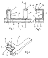
- the adapter 10 according to the invention shown in Figures 1 to 3 is arranged on a main bracket 12 of a not shown cascaded wiper blade.
- Main bracket 12 has two side walls 14, 16 which define a suspension box 18.
- the two side walls 14, 16 each provide a receiving opening 20 extending transversely to the longitudinal axis into which a single-ended plug-in pin 22 of the adapter 10 is inserted.
- the plug-in pin 22 has a cylinder recess 24 for receiving a hinge pin 26, which is arranged in Figures 4 and 6 on the coupling portion 28 of a wiper arm, not shown.
- the adapter 10 has, in the region of the insertion opening 30, a first abutment section 32 for abutting the region 34 of the coupling section 28 holding the hinge pin 26.
- a first abutment section 32 for abutting the region 34 of the coupling section 28 holding the hinge pin 26.
- On the insertion opening 30 side facing away from the adapter 10 has a second abutment portion 36.
- the second abutment portion 36 is used to abut a stop 38 of the adapter 10 in the assembled state at least partially overlapping approach 40 of the coupling portion 28th
- the first abutment section 32 and the second abutment section 36 are designed to be raised in the transverse direction in such a way that the side walls 14, 16 are surmounted in the state mounted on the main bar 12. This ensures that there is no direct contact between the coupling section 28 and the main bar 12. It is also clear from FIG. 2 that the first abutment section 32 is arranged at a distance from the second abutment section 36 in the longitudinal direction.
- the adapter 10 has a longitudinally extending leg 42. As is apparent from Figure 1, the leg 42 is narrower than the side walls 14, 16 is formed so that it does not dominate the side walls 14, 16.
- the second abutment portion 36 is formed in a U-shape in cross section, as shown in Figure 3, wherein a provided on the side wall 14 adjacent cheek 44.
- the cheek 44 which can clearly be seen in particular in FIG. 3, has a catch nose 48 engaging behind the side wall 14 on a side facing away from the back 46 of the abutment section 36.
- the plug pin 22 is inserted into the receiving opening 20.
- the adapter 10 is opposite the main bracket 12 in a direction indicated by the line 50 position.
- the adapter 10 is pivoted to the position shown in the figure 1.
- the detent 48 then engages behind the side wall 14, as shown in FIG.
- a wiper blade 51 arranged on the wiper blade is shown in FIG.
- the cylinder recess 24 has a ventilation opening 54 on its side facing away from the insertion opening 30.
- the designated in Figure 2 with c distance between the first abutment portion 32 and the second abutment portion 36 is dimensioned so that when mounted on the coupling portion 28 adapter 10 a low-backlash guide is ensured. Further, the diameter d of the cylinder recess 24 is selected such that a low-backlash guide with the hinge pin 26 is ensured.
- the adapter 10 shown in Figures 1 to 3 is rotatably held on the main bracket 12 in the mounted state.
- the adapter 100 shown in Figures 4 to 6 in contrast to the adapter 10 is not rotatably held on the main bracket 12, but on the coupling portion 28 of the wiper arm.
- the adapter 100 has, in the region of its second contact section 36, which is U-shaped in cross-section, two latching lugs 56 projecting outwards.
- the locking lugs protrude in the assembled state, as can be seen in particular Figure 5, in the coupling portion 28 existing latching recesses 58.
- the coupling portion 28 shown in Figures 4 to 6 substantially corresponds to a coupling portion, as shown in FIG WO 00/73113 A1 has become known.
- actuating portions 60 are provided, which enable a disassembly of the adapter 100 from the coupling portion 28.
- the operating portions 60 are moved towards each other for disassembly in the direction of arrows 62.
- the latching lugs 56 pass out of the latching recesses 58, and the adapter 100 can be pivoted about the axis of the cylinder recess 24 or of the hinge pin 26 for release from the coupling section 28.
- the adapter 100 according to FIGS. 4, 5 and 6 has the advantage that when the wiper blade together with the adapter 100 is exchanged, all wearing parts are renewed. The coupling section 28 is then not subject to wear.
Landscapes
- Engineering & Computer Science (AREA)
- Mechanical Engineering (AREA)
- Pivots And Pivotal Connections (AREA)
- Dry Shavers And Clippers (AREA)
- Connector Housings Or Holding Contact Members (AREA)
- Cleaning Implements For Floors, Carpets, Furniture, Walls, And The Like (AREA)
Description
- Die Erfindung betrifft einen Adapter zur Adaption eines Hauptbügels eines Wischblatts mit dem Kopplungsabschnitt eines Wischarms einer Wischvorrichtung für Flachwischblätter.
- In zunehmenden Maße verbreiten sich Fahrzeuge mit Wischvorrichtungen, die sogenannte Flachwischblätter aufweisen. Die Flachwischblätter zeichnen sich dadurch aus, dass sie kein kaskadenartiges Bügelsystem aufweisen, sondern ein oder mehrere sich in Wischblattlängsrichtung erstreckende, entsprechend vorgekrümmte elastische Trageelemente. Unter dem Anpressdruck legt sich ein derartiges Wischblatt mit seiner Wischlippe über seine gesamte Länge an der zu wischenden Scheibenoberfläche an. Dabei baut sich im elastischen Trageelement eine Spannung auf, die für eine ordnungsgemäße Anlage der Wischleiste über deren gesamte Länge an der Scheibe sorgt.
- Zur Befestigung eines solchen Flachwischblattes an dem freien Ende des Wischarms ist aus der
WO 00/73113 A1 WO 00/73113 A1 - Es hat sich allerdings gezeigt, dass an den Kopplungsabschnitt derartiger Wischarme ausschließlich dafür vorgesehene Flachwischblätter anordenbar sind. Aufgrund der relativ geringen Verbreitung der Flachwischblätter sind diese nur bedingt verfügbar.
Der vorliegenden Erfindung liegt deshalb die Aufgabe zugrunde, für den Fall Abhilfe zu schaffen, dass selbst bei Nichtverfügbarkeit von Flachwischblättern mit speziell ausgebildetem Befestigungsabschnitt eine ordnungsgemäße Wischung der Scheiben gewährleistet wird. - Diese Aufgabe wird gelöst durch einen Adapter, mit einem einendig gehaltenen Einsteckbolzen zur seitlichen Einführung in eine sich quer zur Wischblattlängsachse erstreckende Aufnahmeöffnung am Hauptbügel, mit einer am Einsteckbolzen vorgesehenen, eine Einführöffnung aufweisenden Zylinderaussparung zur Aufnahme eines Gelenkbolzens des Kopplungsabschnitts des Wischarms, wobei im Bereich der Einführöffnung ein erster Anlageabschnitt vorgesehen ist zur Anlage des den Gelenkbolzen haltenden Bereich des Kopplungsabschnitts, und wobei der Adapter einen auf der der Einführöffnung abgewandten Seite angeordneten zweiten Anlageabschnitt aufweist zur Anlage des Anschlages eines den Adapter im montierten Zustand wenigstens abschnittsweise übergreifenden Ansatzes des Kopplungsabschnitts.
- Hierdurch wird vorteilhafterweise erreicht, dass auch bekannte, weltweit verfügbare Bügelwischblätter, wie sie seit Jahrzehnten Verwendung finden, an den Wischarm einer Wischvorrichtung, die für Flachwischblätter vorgesehen ist, angeordnet werden können. Folglich kann die Betriebssicherheit des entsprechenden Fahrzeugs auch ohne des eigentlich vorgesehenen Flachwischblatts aufgrund des erfindungsgemäßen Adapters durch ein verfügbares Bügelwischblatt erreicht werden. Zur Montage des Adapters wird der Adapter seitlich mit dem Einsteckbolzen in die Aufnahmeöffnung am Hauptbügel eingesteckt. Danach wird der Adapter um die Achse des Einsteckbolzens in die Endmontageposition geschwenkt.
- Um ein bedingtes Verschwenken des Wischblatts gegenüber dem Wischarm zu ermöglichen ist es vorteilhaft, wenn der erste und/oder der zweite Anlageabschnitt in Querrichtung derart erhaben ausgebildet ist, dass im montierten Zustand die jeweilige Seitenwand des Hauptbügels überragt wird. Dadurch werden definierte Berührungspunkte zwischen dem Adapter und Kopplungsabschnitt realisiert. Dabei ist vorzugsweise der erste Anlageabschnitt in Wischblattlängsrichtung von dem zweiten Anlageabschnitt beabstandet angeordnet.
- Die Zylinderaussparung, die zur Aufnahme des Gelenkbolzens des Wischarms dient, kann hierbei beispielsweise als Durchgangsloch oder als Sackloch ausgebildet sein. Die Verwendung eines Sackloches trägt insoweit zur Montagesicherheit bei, als der Gelenkbolzen des Wischarms lediglich in einer Richtung in die Zylinderaussparung einführbar ist. Bei Vorsehen eines Sackloches als Zylinderaussparung ist vorteilhaft, eine Entlüftungsöffnung im Bodenbereich des Sacklochs vorzusehen. Hierdurch kann beispielsweise Regenwasser, das in das Sackloch eindringt, abtrocknen.
- Je nach Breite des Hauptbügels beziehungsweise je nach dem Öffnungsmaß des Sicherungsabschnitts des Wischarm, weist der zweite Anlageabschnitt des Adapters wenigstens ansatzweise eine Wange auf, die im montierten Zustand eine Seitenwand des Hauptbügels wenigstens bedingt umgreift. Hierdurch werden auf das Wischblatt einwirkende Seitenkräfte sicher in den Wischarm abgeleitet.
- Je nach Ausführungsform des Hauptbügels und des Kopplungsabschnitts des Wischarms ist der Anlageabschnitt im Querschnitt L-förmig oder U-förmig ausgebildet.
- Um eine spielarme Führung zwischen Adapter und Kopplungsabschnitt des Wischarms und/oder des Hauptbügels zu erlangen, ist bei einer weiteren Ausführungsform der Erfindung vorgesehen, dass die sich in Querrichtung erstreckende Breite des Anlageabschnitts im montierten Zustand weitgehend formschlüssig vom Ansatz und Anschlag des Kopplungsabschnitts des Wischarms umgriffen wird.
- Der Adapter kann im montierten Zustand entweder drehfest am Hauptbügel oder drehfest am Wischarm gehalten sein. Wird der Adapter drehfest am Wischarm gehalten, so hat dies den Vorteil, dass der Verschleiß an den bewegten Teilen zwischen dem Wischblatt und dem Adapter auftritt. Verschleißteile sind folglich Austauschteile. Der Kopplungsabschnitt des Wischarms unterliegt dann keinem Verschleiß.
- Zur drehfesten Halterung des Adapters kann vorgesehen sein, dass der Adapter wenigstens einen Rastabschnitt zur Verrastung mit dem Hauptbügel oder dem Ansatz beziehungsweise dem Anschlag des Wischarms aufweist. Dabei ist vorteilhaft, wenn der Rastabschnitt beziehungsweise die Rastabschnitte am Anlageabschnitt oder an wenigstens einer Wange des Anlageabschnitts angeordnet sind.
- Um eine sichere Hinterrastung am Hauptbügel beziehungsweise am Ansatz zu erreichen, kann vorgesehen sein, dass der Rastabschnitt beziehungsweise die Rastabschnitte an dem freien Ende beziehungsweise den freien Enden der Wangen des entsprechenden Anlageabschnitts angeordnet sind. Dadurch wird die entsprechende Seitenwand des Hauptbügels nicht nur um-, sondern hintergriffen.
- Der Adapter ist vorzugsweise so ausgebildet, dass zwischen dem Einsteckbolzen und dem zweiten Anlageabschnitt ein sich in Wischblattlängsrichtung erstreckender Schenkel vorgesehen ist, der im montierten Zustand wenigstens abschnittsweise an der ihm zugewandten Seitenwand des Hauptbügels anliegt. Um keinen zusätzlichen Luftwiderstand hervorzurufen, überragt der Schenkel in Seitenansicht die Seitenwände des Hauptbügels nicht.
- Weitere Vorteile und vorteilhafte Ausgestaltungen der Erfindung sind der folgenden Beschreibung zu entnehmen, in der die Erfindung anhand der in der Zeichnung dargestellten Ausführungsbeispiele näher beschrieben und erläutert ist.
- Es zeigen:
- Figur 1
- einen an einem Hauptbügel eines Wischblatts montierten ersten erfindungsgemäßen Adapter in Seitenansicht,
- Figur 2
- einen Schnitt entlang der Linie II durch den Hauptbügel gemäß Figur 1,
- Figur 3
- einen Schnitt entlang der Linie III in Figur 2,
- Figur 4
- eine teilweise freigeschnittene Unteransicht eines zweiten erfindungsgemäßen Adapters an einem Kopplungsabschnitt eines Wischarms,
- Figur 5
- einen Schnitt entlang der Linie V in Figur 4 und
- Figur 6
- eine perspektivische Ansicht des Adapters gemäß Figur 4 von schräg oben.
- Der in den Figuren 1 bis 3 gezeigte erfindungsgemäße Adapter 10 ist an einem Hauptbügel 12 eines nicht dargestellten kaskadenartig aufgebauten Bügelwischblatts angeordnet. Der Hauptbügel 12 weist zwei Seitenwände 14, 16 auf, die einen Einhängekasten 18 begrenzen. Die beiden Seitenwände 14, 16 sehen jeweils eine sich quer zur Längsachse erstreckende Aufnahmeöffnung 20 vor, in die ein einendig gehaltener Einsteckbolzen 22 des Adapters 10 eingeführt ist. Der Einsteckbolzen 22 weist eine Zylinderaussparung 24 zur Aufnahme eines Gelenkbolzens 26 auf, der in den Figuren 4 und 6 am Kopplungsabschnitt 28 eines nicht dargestellten Wischarmes angeordnet ist. Wie aus Figur 2 deutlich wird, weist der Adapter 10 im Bereich der Einführöffnung 30 einen ersten Anlageabschnitt 32 zur Anlage des den Gelenkbolzen 26 haltenden Bereich 34 des Kopplungsabschnitts 28 auf. Auf der Einführöffnung 30 abgewandten Seite weist der Adapter 10 einen zweiten Anlageabschnitt 36 auf. Der zweite Anlageabschnitt 36 dient zur Anlage eines Anschlags 38 eines den Adapter 10 im montierten Zustand wenigstens abschnittsweise übergreifenden Ansatzes 40 des Kopplungsabschnitts 28.
- Bei dem in den Figuren 1 bis 3 gezeigten Adapter ist der erste Anlageabschnitt 32 und der zweite Anlageabschnitt 36 in Querrichtung derart erhaben ausgebildet, dass in am Hauptbügel 12 montierten Zustand die Seitenwände 14, 16 überragt werden. Hierdurch wird gewährleistet, dass zwischen dem Kopplungsabschnitt 28 und dem Hauptbügel 12 kein direkter Kontakt besteht. Aus Figur 2 wird ebenfalls deutlich, dass der erste Anlageabschnitt 32 in Längsrichtung von dem zweiten Anlageabschnitt 36 beabstandet angeordnet ist.
- Zwischen dem ersten Anlageabschnitt 32 und dem zweiten Anlageabschnitt 36 weist der Adapter 10 einen sich in Längsrichtung erstreckenden Schenkel 42 auf. Wie aus Figur 1 deutlich wird, ist der Schenkel 42 schmaler als die Seitenwände 14, 16 ausgebildet, so dass er die Seitenwände 14, 16 nicht überragt.
- Der zweite Anlageabschnitt 36 ist im Querschnitt, wie er in der Figur 3 dargestellt ist, U-förmig ausgebildet, wobei eine an der Seitenwand 14 anliegende Wange 44 vorgesehen ist. Die insbesondere in der Figur 3 deutlich zu erkennende Wange 44 weist auf einer dem Rücken 46 des Anlageabschnitts 36 abgewandten Seite eine die Seitenwand 14 hintergreifende Rastnase 48 auf.
- Zur Montage des Adapters 10 an dem Hauptbügel 12 wird der Einsteckbolzen 22 in die Aufnahmeöffnung 20 eingeführt. Dabei befindet sich der Adapter 10 gegenüber dem Hauptbügel 12 in einer mit der Linie 50 angedeuteten Lage. Nachdem der Einsteckbolzen 22 in den Hauptbügel 12 eingesteckt ist, wird der Adapter 10 in die in der Figur 1 dargestellten Lage verschwenkt. Die Rastnase 48 hinterrastet dann die Seitenwand 14, wie es in der Figur 3 dargestellt ist.
- In der Figur 3 ist neben dem Hauptbügel 12 und dem Adapter 10 außerdem ein an dem Wischblatt angeordneten Wischgummi 51 dargestellt.
- Erfindungsgemäß ist ferner denkbar, dass an der dem Rücken 46 abgewandten Kante 52 des Schenkels 42 ebenfalls eine nicht dargestellte Rastnase vorgesehen ist, die die Seitenwand 16 hinterrastet.
- Wie in der Figur 2 deutlich wird, weist die Zylinderaussparung 24 auf ihrer der Einführöffnung 30 abgewandten Seite eine Entlüftungsöffnung 54 auf.
- Der in der Figur 2 mit c bezeichnete Abstand zwischen dem ersten Anlageabschnitt 32 und dem zweiten Anlageabschnitt 36 ist so bemessen, dass bei am Kopplungsabschnitt 28 montiertem Adapter 10 eine spielarme Führung gewährleistet wird. Ferner ist der Durchmesser d der Zylinderaussparung 24 derart gewählt, dass eine spielarme Führung mit dem Gelenkbolzen 26 gewährleistet wird.
- Der in den Figuren 1 bis 3 dargestellte Adapter 10 ist im montierten Zustand drehfest am Hauptbügel 12 gehalten.
- Der in den Figuren 4 bis 6 dargestellte Adapter 100 ist im Gegensatz zum Adapter 10 nicht am Hauptbügel 12, sondern am Kopplungsabschnitt 28 des Wischerarms drehfest gehalten. Der Adapter 100 weist hierfür im Bereich seines im Querschnitt U-förmig ausgebildeten zweiten Anlageabschnitts 36 zwei nach außen ragende Rastnasen 56 auf. Die Rastnasen ragen im montierten Zustand, wie insbesondere Figur 5 entnommen werden kann, in am Kopplungsabschnitt 28 vorhandene Rastaussparungen 58. Der in den Figuren 4 bis 6 dargestellte Kopplungsabschnitt 28 entspricht im wesentlichen einem Kopplungsabschnitt, wie er aus der
WO 00/73113 A1 - An den dem Rücken 46 abgewandten Kanten 52 des Adapters 100 sind Betätigungsabschnitte 60 vorgesehen, die eine Demontage des Adapters 100 vom Kopplungsabschnitt 28 ermöglichen. Die Betätigungsabschnitte 60 werden zur Demontage in Richtung der Pfeile 62 aufeinander zu bewegt. Hierdurch gelangen die Rastnasen 56 aus den Rastaussparungen 58, und der Adapter 100 kann zum Lösen vom Kopplungsabschnitt 28 um die Achse der Zylinderaussparung 24 beziehungsweise des Gelenkbolzens 26 verschwenkt werden.
- Der Adapter 100 gemäß den Figuren 4, 5 und 6 hat den Vorteil, dass wenn das Wischblatt samt Adapter 100 ausgetauscht wird, sämtliche Verschleißteile erneuert werden. Der Kopplungsabschnitt 28 unterliegt dann keinem Verschleiß.
- Aufgrund des erfindungsgemäßen Adapters 10, 100 ist es möglich, bekannte Bügelwischblätter an den eigentlich für Flachwischblätter vorgesehenen Kopplungsabschnitt 30 anzuordnen.
Claims (14)
- Adapter (10, 100) zur Adaption eines Hauptbügels (12) eines Wischblatts mit dem Kopplungsabschnitt (28) eines Wischarms einer Wischvorrichtung,
mit einem einendig gehaltenen Einsteckbolzen (22) zur seitlichen Einführung in eine sich quer zur Wischblattlängsachse erstreckende Aufnahmeöffnung (20) am Hauptbügel (12),
mit einer am Einsteckbolzen (22) vorgesehenen, eine Einführöffnung (30) aufweisenden Zylinderaussparung (24) zur Aufnahme eines Gelenkbolzens (26) des Kopplungsabschnitts (28) des Wischarms,
wobei im Bereich der Einführöffnung (30) ein erster Anlageabschnitt (32) vorgesehen ist zur Anlage des den Gelenkbolzen (26) haltenden Bereiches des Kopplungsabschnitts (28), dadurch gekennzeichnet, daß der Adapter (10) einen auf der der Einführöffnung (30) abgewandten Seite angeordneten zweiten Anlageabschnitt (36) aufweist zur Anlage des Anschlages (38) eines den Adapter (10, 100) im montierten Zustand wenigstens abschnittsweise übergreifenden Ansatzes (40) des Kopplungsabschnitts (28). - Adapter (10, 100) nach Anspruch 1, dadurch gekennzeichnet, dass der erste (32) und/oder der zweite Anlageabschnitt (36) in Querrichtung derart erhaben ausgebildet ist, dass in am Hauptbügel (12) montierten Zustand die jeweilige Seitenwand (14, 16) des Hauptbügels (12) überragt wird.
- Adapter (10, 100) nach Anspruch 1 oder 2, dadurch gekennzeichnet, dass der erste Anlageabschnitt (32) in Wischblattlängsrichtung von dem zweiten Anlageabschnitt (36) beabstandet angeordnet ist.
- Adapter (10, 100) nach Anspruch 1, 2 oder 3, dadurch gekennzeichnet, dass die Zylinderaussparung (24) als Durchgangsloch oder als Sackloch ausgebildet ist.
- Adapter (10, 100) nach einem der vorhergehenden Ansprüche, dadurch gekennzeichnet, dass der zweite Anlageabschnitt (36) wenigstens ansatzweise eine Wange (44, 42) aufweist, die im montierten Zustand wenigstens eine Seitenwand (14, 16) des Hauptbügels (12) wenigstens bedingt umgreift.
- Adapter (10, 100) nach einem der vorhergehenden Ansprüche, dadurch gekennzeichnet, dass der zweite Anlageabschnitt (36) im Querschnitt L-förmig oder U-förmig ausgebildet ist.
- Adapter (10, 100) nach einem der vorhergehenden Ansprüche, dadurch gekennzeichnet, dass die sich in Querrichtung erstreckende Breite des zweiten Anlageabschnitts (36) im montierten Zustand weitgehend formschlüssig vom Ansatz und Anschlag (38, 40) des Kopplungsabschnitts (28) des Wischarms umgriffen wird.
- Adapter (10, 100) nach einem der vorhergehenden Ansprüche, dadurch gekennzeichnet, dass der Adapter (10, 100) im montierten Zustand drehfest am Hauptbügel (12) gehalten ist.
- Adapter (10, 100) nach einem der vorhergehenden Ansprüche, dadurch gekennzeichnet, dass der Adapter (10, 100) im montierten Zustand drehfest am Kopplungsabschnitt (28) des Wischarms gehalten ist.
- Adapter (10, 100) nach einem der vorhergehenden Ansprüche, dadurch gekennzeichnet, dass der Adapter (10, 100) wenigstens einen Rastabschnitt (48, 56) zur Verrastung mit dem Hauptbügel (12) und/oder dem Kopplungsabschnitt (28) aufweist.
- Adapter (10, 100) nach einem der vorhergehenden Ansprüche, dadurch gekennzeichnet, dass der Rastabschnitt bzw. die Rastabschnitte (48, 56) am zweiten Anlageabschnitt (36) angeordnet sind.
- Adapter (10, 100) nach einem der vorhergehenden Ansprüche, dadurch gekennzeichnet, dass der Rastabschnitt bzw. die Rastabschnitte an dem freien Ende (52) bzw. den freien Enden der Wangen (42, 44) des zweiten Anlageabschnitts (36) angeordnet sind.
- Adapter (10, 100) nach einem der vorhergehenden Ansprüche, dadurch gekennzeichnet, dass der Adapter (10, 100) zwischen dem Einsteckbolzen (22) und dem zweiten Anlageabschnitt (36) einen sich in Wischblattlängsrichtung erstreckenden Schenkel (42) aufweist, der im montierten Zustand wenigstens abschnittsweise an einer Seitenwand (16) des Hauptbügels (12) anliegt.
- Adapter (10, 100) nach Anspruch 13, dadurch gekennzeichnet, dass der Schenkel (42) die Seitenwände in des Hauptbügels (12) nicht überragt.
Applications Claiming Priority (3)
| Application Number | Priority Date | Filing Date | Title |
|---|---|---|---|
| DE10251520 | 2002-11-04 | ||
| DE10251520A DE10251520A1 (de) | 2002-11-04 | 2002-11-04 | Adapter für ein Wischblatt |
| PCT/EP2003/012000 WO2004041605A1 (de) | 2002-11-04 | 2003-10-29 | Adapter für ein wischblatt |
Publications (2)
| Publication Number | Publication Date |
|---|---|
| EP1558476A1 EP1558476A1 (de) | 2005-08-03 |
| EP1558476B1 true EP1558476B1 (de) | 2007-08-08 |
Family
ID=32103354
Family Applications (1)
| Application Number | Title | Priority Date | Filing Date |
|---|---|---|---|
| EP03778293A Expired - Lifetime EP1558476B1 (de) | 2002-11-04 | 2003-10-29 | Adapter für ein wischblatt |
Country Status (8)
| Country | Link |
|---|---|
| US (1) | US7676881B2 (de) |
| EP (1) | EP1558476B1 (de) |
| CN (1) | CN100377935C (de) |
| AT (1) | ATE369272T1 (de) |
| AU (1) | AU2003285307A1 (de) |
| DE (2) | DE10251520A1 (de) |
| ES (1) | ES2291714T3 (de) |
| WO (1) | WO2004041605A1 (de) |
Families Citing this family (1)
| Publication number | Priority date | Publication date | Assignee | Title |
|---|---|---|---|---|
| ITMI20041965A1 (it) * | 2004-10-15 | 2005-01-15 | Augusto Amici | "dna codificante forme tronche e chimeriche della proteina p185neu e suoi usi terapeutici" |
Family Cites Families (13)
| Publication number | Priority date | Publication date | Assignee | Title |
|---|---|---|---|---|
| US4007511A (en) | 1975-04-07 | 1977-02-15 | Trico Products Corporation | Vehicle windshield wiper blade assemblies |
| US4132490A (en) | 1975-06-07 | 1979-01-02 | Paul Journee, S.A. | Device for securing a wiper blade to an arm |
| FR2324489A1 (fr) * | 1975-09-16 | 1977-04-15 | Journee Paul Sa | Dispositif de fixation d'un balai d'essuie-glace sur un bras |
| IT1144605B (it) * | 1981-06-09 | 1986-10-29 | Arman Spa | Dispositivo d attacco per tergicristalli |
| US4970751A (en) * | 1989-04-17 | 1990-11-20 | Tridon Limited | Adaptor for windshield wiper pin |
| US5715563A (en) * | 1996-11-04 | 1998-02-10 | Worktools, Inc. | Windshield wiper bracket |
| DE19838883A1 (de) * | 1998-08-27 | 2000-03-02 | Bosch Gmbh Robert | Vorrichtung zum Verbinden eines Wischblatts mit einem Wischerarm |
| HU226808B1 (en) * | 1999-05-28 | 2009-11-30 | Bosch Gmbh Robert | Wiper blade for the glass surfaces of a motor vehicle |
| DE19924662B4 (de) | 1999-05-28 | 2007-06-28 | Robert Bosch Gmbh | Wischvorrichtung für Scheiben von Kraftfahrzeugen |
| DE10100847A1 (de) * | 2001-01-05 | 2002-07-11 | Volkswagen Ag | Wischervorrichtung mit einem Anschlußelement zur Befestigung des Wischblatts an dem Wischerarm |
| DE10108200A1 (de) * | 2001-02-21 | 2002-08-22 | Bosch Gmbh Robert | Wischvorrichtung insbesondere für Scheiben von Kraftfahrzeugen |
| DE10162402B4 (de) * | 2001-12-19 | 2006-10-19 | Robert Bosch Gmbh | Wischblatt |
| DE102004017722A1 (de) * | 2004-04-10 | 2005-10-27 | Robert Bosch Gmbh | Adapter zum gelenkigen Verbinden eines Wischblatts mit einem Wischarm |
-
2002
- 2002-11-04 DE DE10251520A patent/DE10251520A1/de not_active Withdrawn
-
2003
- 2003-10-29 AT AT03778293T patent/ATE369272T1/de not_active IP Right Cessation
- 2003-10-29 WO PCT/EP2003/012000 patent/WO2004041605A1/de not_active Ceased
- 2003-10-29 US US10/533,668 patent/US7676881B2/en not_active Expired - Fee Related
- 2003-10-29 AU AU2003285307A patent/AU2003285307A1/en not_active Abandoned
- 2003-10-29 ES ES03778293T patent/ES2291714T3/es not_active Expired - Lifetime
- 2003-10-29 EP EP03778293A patent/EP1558476B1/de not_active Expired - Lifetime
- 2003-10-29 CN CNB2003801023617A patent/CN100377935C/zh not_active Expired - Fee Related
- 2003-10-29 DE DE50307904T patent/DE50307904D1/de not_active Expired - Lifetime
Non-Patent Citations (1)
| Title |
|---|
| None * |
Also Published As
| Publication number | Publication date |
|---|---|
| AU2003285307A1 (en) | 2004-06-07 |
| ATE369272T1 (de) | 2007-08-15 |
| CN100377935C (zh) | 2008-04-02 |
| CN1708428A (zh) | 2005-12-14 |
| DE10251520A1 (de) | 2004-05-13 |
| EP1558476A1 (de) | 2005-08-03 |
| US20060143848A1 (en) | 2006-07-06 |
| ES2291714T3 (es) | 2008-03-01 |
| DE50307904D1 (de) | 2007-09-20 |
| US7676881B2 (en) | 2010-03-16 |
| WO2004041605A1 (de) | 2004-05-21 |
Similar Documents
| Publication | Publication Date | Title |
|---|---|---|
| EP1565359B1 (de) | Vorrichtung zum lösbaren verbinden eines wischblatts mit einem antreibbaren wischarm | |
| EP2321160B1 (de) | Vorrichtung zum gelenkigen verbinden eines wischblatts mit einem wischarm eines scheibenwischers | |
| EP2736775B1 (de) | Anschlussvorrichtung zum gelenkigen verbinden eines wischblatts mit einem wischarm und ein adapter | |
| EP1485280A1 (de) | Wischvorrichtung mit flachwischblatt und wischarm | |
| DE102008000708A1 (de) | Wischblatt | |
| DE10065014A1 (de) | Wischvorrichtung, insbesondere für Scheiben von Kraftfahrzeugen | |
| EP1056628A1 (de) | Vorrichtung zum gelenkigen verbinden eines wischblatts für scheiben von kraftfahrzeugen mit einem wischerarm und verfahren zum herstellen dieser verbindung | |
| EP1337420A1 (de) | Wischhebel mit einem angetriebenen wischerarm und einem an diesem angelenkten wischblatt zum reinigen von scheiben insbesondere von kraftfahrzeugen | |
| WO2002052917A2 (de) | Vorrichtung zum lösbaren verbinden eines wischblatts mit einem wischerarm | |
| DE19857375A1 (de) | Wischervorrichtung | |
| DE10043427B4 (de) | Wischvorrichtung | |
| DE10230457B4 (de) | Anschlussvorrichtung für einen Scheibenwischer | |
| EP1824717B1 (de) | Wischblatt | |
| EP1558476B1 (de) | Adapter für ein wischblatt | |
| EP0709267B1 (de) | Wischvorrichtung für Scheiben von Kraftfahrzeugen | |
| DE8205994U1 (de) | Wischarm, insbesondere fuer scheibenwischeranlagen von kraftfahrzeugen | |
| EP2108552B1 (de) | Scheibenwischer, insbesondere für Kraftfahrzeuge | |
| EP0966374A1 (de) | Lagerteil zum anlenken eines wischerblatts | |
| WO2005002934A1 (de) | Verbindung zwischen einem wischblatt und einem wischarm einer wischvorrichtung für scheiben an fahrzeugen, sowie wischvorrichtung mit einer solchen verbindung | |
| DE102015011370A1 (de) | Wischblatt für eine Scheibenwischanlage eines Fahrzeugs und Verbindungsanordnung mit einem Wischblatt und einem Wischarm | |
| DE10040530A1 (de) | Wischvorrichtung, insbesondere für Kraftfahrzeuge | |
| DE10043426A1 (de) | Wischvorrichtung | |
| EP1567397A1 (de) | Adapter für ein wischblatt | |
| EP1140587A1 (de) | Gelenkige verbindung | |
| DE10162402B4 (de) | Wischblatt |
Legal Events
| Date | Code | Title | Description |
|---|---|---|---|
| PUAI | Public reference made under article 153(3) epc to a published international application that has entered the european phase |
Free format text: ORIGINAL CODE: 0009012 |
|
| 17P | Request for examination filed |
Effective date: 20050425 |
|
| AK | Designated contracting states |
Kind code of ref document: A1 Designated state(s): AT BE BG CH CY CZ DE DK EE ES FI FR GB GR HU IE IT LI LU MC NL PT RO SE SI SK TR |
|
| AX | Request for extension of the european patent |
Extension state: AL LT LV MK |
|
| DAX | Request for extension of the european patent (deleted) | ||
| GRAP | Despatch of communication of intention to grant a patent |
Free format text: ORIGINAL CODE: EPIDOSNIGR1 |
|
| GRAS | Grant fee paid |
Free format text: ORIGINAL CODE: EPIDOSNIGR3 |
|
| GRAA | (expected) grant |
Free format text: ORIGINAL CODE: 0009210 |
|
| AK | Designated contracting states |
Kind code of ref document: B1 Designated state(s): AT BE BG CH CY CZ DE DK EE ES FI FR GB GR HU IE IT LI LU MC NL PT RO SE SI SK TR |
|
| REG | Reference to a national code |
Ref country code: GB Ref legal event code: FG4D Free format text: NOT ENGLISH |
|
| REG | Reference to a national code |
Ref country code: CH Ref legal event code: EP |
|
| REG | Reference to a national code |
Ref country code: IE Ref legal event code: FG4D Free format text: LANGUAGE OF EP DOCUMENT: GERMAN |
|
| REF | Corresponds to: |
Ref document number: 50307904 Country of ref document: DE Date of ref document: 20070920 Kind code of ref document: P |
|
| ET | Fr: translation filed | ||
| PG25 | Lapsed in a contracting state [announced via postgrant information from national office to epo] |
Ref country code: NL Free format text: LAPSE BECAUSE OF FAILURE TO SUBMIT A TRANSLATION OF THE DESCRIPTION OR TO PAY THE FEE WITHIN THE PRESCRIBED TIME-LIMIT Effective date: 20070808 Ref country code: BG Free format text: LAPSE BECAUSE OF FAILURE TO SUBMIT A TRANSLATION OF THE DESCRIPTION OR TO PAY THE FEE WITHIN THE PRESCRIBED TIME-LIMIT Effective date: 20071108 Ref country code: FI Free format text: LAPSE BECAUSE OF FAILURE TO SUBMIT A TRANSLATION OF THE DESCRIPTION OR TO PAY THE FEE WITHIN THE PRESCRIBED TIME-LIMIT Effective date: 20070808 |
|
| NLV1 | Nl: lapsed or annulled due to failure to fulfill the requirements of art. 29p and 29m of the patents act | ||
| REG | Reference to a national code |
Ref country code: ES Ref legal event code: FG2A Ref document number: 2291714 Country of ref document: ES Kind code of ref document: T3 |
|
| GBV | Gb: ep patent (uk) treated as always having been void in accordance with gb section 77(7)/1977 [no translation filed] |
Effective date: 20070808 |
|
| REG | Reference to a national code |
Ref country code: IE Ref legal event code: FD4D |
|
| PG25 | Lapsed in a contracting state [announced via postgrant information from national office to epo] |
Ref country code: GR Free format text: LAPSE BECAUSE OF FAILURE TO SUBMIT A TRANSLATION OF THE DESCRIPTION OR TO PAY THE FEE WITHIN THE PRESCRIBED TIME-LIMIT Effective date: 20071109 Ref country code: DK Free format text: LAPSE BECAUSE OF FAILURE TO SUBMIT A TRANSLATION OF THE DESCRIPTION OR TO PAY THE FEE WITHIN THE PRESCRIBED TIME-LIMIT Effective date: 20070808 |
|
| PGFP | Annual fee paid to national office [announced via postgrant information from national office to epo] |
Ref country code: GB Payment date: 20071016 Year of fee payment: 5 |
|
| PG25 | Lapsed in a contracting state [announced via postgrant information from national office to epo] |
Ref country code: GB Free format text: LAPSE BECAUSE OF FAILURE TO SUBMIT A TRANSLATION OF THE DESCRIPTION OR TO PAY THE FEE WITHIN THE PRESCRIBED TIME-LIMIT Effective date: 20070808 Ref country code: IE Free format text: LAPSE BECAUSE OF FAILURE TO SUBMIT A TRANSLATION OF THE DESCRIPTION OR TO PAY THE FEE WITHIN THE PRESCRIBED TIME-LIMIT Effective date: 20070808 Ref country code: MC Free format text: LAPSE BECAUSE OF NON-PAYMENT OF DUE FEES Effective date: 20071031 Ref country code: CZ Free format text: LAPSE BECAUSE OF FAILURE TO SUBMIT A TRANSLATION OF THE DESCRIPTION OR TO PAY THE FEE WITHIN THE PRESCRIBED TIME-LIMIT Effective date: 20070808 Ref country code: PT Free format text: LAPSE BECAUSE OF FAILURE TO SUBMIT A TRANSLATION OF THE DESCRIPTION OR TO PAY THE FEE WITHIN THE PRESCRIBED TIME-LIMIT Effective date: 20080108 Ref country code: SK Free format text: LAPSE BECAUSE OF FAILURE TO SUBMIT A TRANSLATION OF THE DESCRIPTION OR TO PAY THE FEE WITHIN THE PRESCRIBED TIME-LIMIT Effective date: 20070808 |
|
| PLBE | No opposition filed within time limit |
Free format text: ORIGINAL CODE: 0009261 |
|
| STAA | Information on the status of an ep patent application or granted ep patent |
Free format text: STATUS: NO OPPOSITION FILED WITHIN TIME LIMIT |
|
| REG | Reference to a national code |
Ref country code: CH Ref legal event code: PL |
|
| PG25 | Lapsed in a contracting state [announced via postgrant information from national office to epo] |
Ref country code: SE Free format text: LAPSE BECAUSE OF FAILURE TO SUBMIT A TRANSLATION OF THE DESCRIPTION OR TO PAY THE FEE WITHIN THE PRESCRIBED TIME-LIMIT Effective date: 20071108 Ref country code: RO Free format text: LAPSE BECAUSE OF FAILURE TO SUBMIT A TRANSLATION OF THE DESCRIPTION OR TO PAY THE FEE WITHIN THE PRESCRIBED TIME-LIMIT Effective date: 20070808 |
|
| 26N | No opposition filed |
Effective date: 20080509 |
|
| PG25 | Lapsed in a contracting state [announced via postgrant information from national office to epo] |
Ref country code: CH Free format text: LAPSE BECAUSE OF NON-PAYMENT OF DUE FEES Effective date: 20071031 Ref country code: LI Free format text: LAPSE BECAUSE OF NON-PAYMENT OF DUE FEES Effective date: 20071031 |
|
| PG25 | Lapsed in a contracting state [announced via postgrant information from national office to epo] |
Ref country code: EE Free format text: LAPSE BECAUSE OF FAILURE TO SUBMIT A TRANSLATION OF THE DESCRIPTION OR TO PAY THE FEE WITHIN THE PRESCRIBED TIME-LIMIT Effective date: 20070808 |
|
| PG25 | Lapsed in a contracting state [announced via postgrant information from national office to epo] |
Ref country code: AT Free format text: LAPSE BECAUSE OF NON-PAYMENT OF DUE FEES Effective date: 20071029 |
|
| PG25 | Lapsed in a contracting state [announced via postgrant information from national office to epo] |
Ref country code: SI Free format text: LAPSE BECAUSE OF FAILURE TO SUBMIT A TRANSLATION OF THE DESCRIPTION OR TO PAY THE FEE WITHIN THE PRESCRIBED TIME-LIMIT Effective date: 20070808 |
|
| PG25 | Lapsed in a contracting state [announced via postgrant information from national office to epo] |
Ref country code: CY Free format text: LAPSE BECAUSE OF FAILURE TO SUBMIT A TRANSLATION OF THE DESCRIPTION OR TO PAY THE FEE WITHIN THE PRESCRIBED TIME-LIMIT Effective date: 20070808 |
|
| PG25 | Lapsed in a contracting state [announced via postgrant information from national office to epo] |
Ref country code: LU Free format text: LAPSE BECAUSE OF NON-PAYMENT OF DUE FEES Effective date: 20071029 |
|
| PG25 | Lapsed in a contracting state [announced via postgrant information from national office to epo] |
Ref country code: TR Free format text: LAPSE BECAUSE OF FAILURE TO SUBMIT A TRANSLATION OF THE DESCRIPTION OR TO PAY THE FEE WITHIN THE PRESCRIBED TIME-LIMIT Effective date: 20070808 Ref country code: HU Free format text: LAPSE BECAUSE OF FAILURE TO SUBMIT A TRANSLATION OF THE DESCRIPTION OR TO PAY THE FEE WITHIN THE PRESCRIBED TIME-LIMIT Effective date: 20080209 |
|
| REG | Reference to a national code |
Ref country code: FR Ref legal event code: PLFP Year of fee payment: 13 |
|
| REG | Reference to a national code |
Ref country code: FR Ref legal event code: PLFP Year of fee payment: 14 |
|
| PGFP | Annual fee paid to national office [announced via postgrant information from national office to epo] |
Ref country code: ES Payment date: 20161027 Year of fee payment: 14 Ref country code: IT Payment date: 20161011 Year of fee payment: 14 Ref country code: BE Payment date: 20161027 Year of fee payment: 14 |
|
| REG | Reference to a national code |
Ref country code: FR Ref legal event code: PLFP Year of fee payment: 15 |
|
| REG | Reference to a national code |
Ref country code: BE Ref legal event code: MM Effective date: 20171031 |
|
| PG25 | Lapsed in a contracting state [announced via postgrant information from national office to epo] |
Ref country code: BE Free format text: LAPSE BECAUSE OF NON-PAYMENT OF DUE FEES Effective date: 20171031 |
|
| REG | Reference to a national code |
Ref country code: FR Ref legal event code: PLFP Year of fee payment: 16 |
|
| PG25 | Lapsed in a contracting state [announced via postgrant information from national office to epo] |
Ref country code: IT Free format text: LAPSE BECAUSE OF NON-PAYMENT OF DUE FEES Effective date: 20171029 |
|
| REG | Reference to a national code |
Ref country code: ES Ref legal event code: FD2A Effective date: 20181221 |
|
| PG25 | Lapsed in a contracting state [announced via postgrant information from national office to epo] |
Ref country code: ES Free format text: LAPSE BECAUSE OF NON-PAYMENT OF DUE FEES Effective date: 20171030 |
|
| PGFP | Annual fee paid to national office [announced via postgrant information from national office to epo] |
Ref country code: DE Payment date: 20191009 Year of fee payment: 17 |
|
| PGFP | Annual fee paid to national office [announced via postgrant information from national office to epo] |
Ref country code: FR Payment date: 20191031 Year of fee payment: 17 |
|
| REG | Reference to a national code |
Ref country code: DE Ref legal event code: R119 Ref document number: 50307904 Country of ref document: DE |
|
| PG25 | Lapsed in a contracting state [announced via postgrant information from national office to epo] |
Ref country code: FR Free format text: LAPSE BECAUSE OF NON-PAYMENT OF DUE FEES Effective date: 20201031 Ref country code: DE Free format text: LAPSE BECAUSE OF NON-PAYMENT OF DUE FEES Effective date: 20210501 |