EP1558476B1 - Adaptateur pour un balai d'essuie-glace - Google Patents
Adaptateur pour un balai d'essuie-glace Download PDFInfo
- Publication number
- EP1558476B1 EP1558476B1 EP03778293A EP03778293A EP1558476B1 EP 1558476 B1 EP1558476 B1 EP 1558476B1 EP 03778293 A EP03778293 A EP 03778293A EP 03778293 A EP03778293 A EP 03778293A EP 1558476 B1 EP1558476 B1 EP 1558476B1
- Authority
- EP
- European Patent Office
- Prior art keywords
- adapter
- section
- main yoke
- bearing
- wiper
- Prior art date
- Legal status (The legal status is an assumption and is not a legal conclusion. Google has not performed a legal analysis and makes no representation as to the accuracy of the status listed.)
- Expired - Lifetime
Links
- 238000003780 insertion Methods 0.000 claims abstract description 15
- 230000037431 insertion Effects 0.000 claims abstract description 15
- 230000008878 coupling Effects 0.000 claims description 33
- 238000010168 coupling process Methods 0.000 claims description 33
- 238000005859 coupling reaction Methods 0.000 claims description 33
- 238000010409 ironing Methods 0.000 description 3
- 230000015572 biosynthetic process Effects 0.000 description 1
- 230000000295 complement effect Effects 0.000 description 1
- 239000000725 suspension Substances 0.000 description 1
- 238000009423 ventilation Methods 0.000 description 1
Images

Classifications
-
- B—PERFORMING OPERATIONS; TRANSPORTING
- B60—VEHICLES IN GENERAL
- B60S—SERVICING, CLEANING, REPAIRING, SUPPORTING, LIFTING, OR MANOEUVRING OF VEHICLES, NOT OTHERWISE PROVIDED FOR
- B60S1/00—Cleaning of vehicles
- B60S1/02—Cleaning windscreens, windows or optical devices
- B60S1/04—Wipers or the like, e.g. scrapers
- B60S1/32—Wipers or the like, e.g. scrapers characterised by constructional features of wiper blade arms or blades
- B60S1/40—Connections between blades and arms
- B60S1/4067—Connections between blades and arms for arms provided with a side pin
- B60S1/407—Connections between blades and arms for arms provided with a side pin with means provided on the arm for locking the side pin
Definitions
- the invention relates to an adapter for adapting a main bracket of a wiper blade to the coupling portion of a wiper arm of a wiper device for flat wiper blades.
- the flat wiper blades are characterized by the fact that they do not have a cascade-like ironing system, but one or more extending in wiper blade longitudinal direction, corresponding pre-curved elastic support elements. Under the pressure applied to such a wiper blade with its wiper lip over its entire length at the window surface to be wiped. In this case, a tension builds up in the elastic support element, which ensures a proper contact of the wiper strip over its entire length on the disc.
- an adapter with a single-ended plug pin for lateral insertion into a transverse to the wiper blade longitudinal receiving opening on the main frame, with an insertion bolt provided on the insertion opening having a cylinder recess for receiving a hinge pin of the coupling portion of the wiper arm, wherein in the Insertion opening a first abutment portion is provided for abutment of the hinge pin holding portion of the coupling portion, and wherein the adapter arranged on the side facing away from the insertion opening second abutment portion for abutment of the stop of the adapter in the assembled state at least partially overlapping approach of the coupling portion.
- the first and / or the second abutment section is designed to be raised in the transverse direction in such a way that in the assembled state the respective side wall of the main bracket is surmounted.
- the first contact section is preferably arranged spaced apart in the wiper blade longitudinal direction from the second contact section.
- the cylinder recess which serves to receive the hinge pin of the wiper arm, may in this case be formed, for example, as a through hole or as a blind hole.
- the use of a blind hole contributes to the extent to assembly safety, as the hinge pin of the wiper arm can be inserted only in one direction in the cylinder recess.
- When providing a blind hole as a cylinder recess is advantageous to provide a vent opening in the bottom region of the blind hole. As a result, for example, rainwater that penetrates into the blind hole, dry off.
- the second contact portion of the adapter at least partially a cheek, which at least partially engages in the mounted state, a side wall of the main bracket.
- main bracket and the coupling portion of the wiper arm of the contact portion is formed in cross-section L-shaped or U-shaped.
- the adapter can be held in the assembled state either rotatably on the main bracket or rotation on the wiper arm. If the adapter rotatably held on the wiper arm, this has the advantage that the wear on the moving parts between the wiper blade and the adapter occurs. Wear parts are therefore replacement parts. The coupling portion of the wiper arm is then subject to no wear.
- the adapter has at least one latching portion for locking with the main bracket or the approach or the stop of the wiper arm. It is advantageous if the latching section or the latching sections are arranged on the contact section or on at least one cheek of the contact section.
- the latching portion or the latching portions are arranged at the free end or the free ends of the cheeks of the corresponding contact portion.
- the corresponding side wall of the main bracket is not only re-engaged, but behind.
- the adapter is preferably designed such that a leg extending in the wiper blade longitudinal direction is provided between the plug-in bolt and the second contact section, said leg lying in the assembled state at least in sections against the side wall of the main bracket facing it. In order not to cause additional air resistance, the leg does not protrude in side view, the side walls of the main bracket.
- the adapter 10 according to the invention shown in Figures 1 to 3 is arranged on a main bracket 12 of a not shown cascaded wiper blade.
- Main bracket 12 has two side walls 14, 16 which define a suspension box 18.
- the two side walls 14, 16 each provide a receiving opening 20 extending transversely to the longitudinal axis into which a single-ended plug-in pin 22 of the adapter 10 is inserted.
- the plug-in pin 22 has a cylinder recess 24 for receiving a hinge pin 26, which is arranged in Figures 4 and 6 on the coupling portion 28 of a wiper arm, not shown.
- the adapter 10 has, in the region of the insertion opening 30, a first abutment section 32 for abutting the region 34 of the coupling section 28 holding the hinge pin 26.
- a first abutment section 32 for abutting the region 34 of the coupling section 28 holding the hinge pin 26.
- On the insertion opening 30 side facing away from the adapter 10 has a second abutment portion 36.
- the second abutment portion 36 is used to abut a stop 38 of the adapter 10 in the assembled state at least partially overlapping approach 40 of the coupling portion 28th
- the first abutment section 32 and the second abutment section 36 are designed to be raised in the transverse direction in such a way that the side walls 14, 16 are surmounted in the state mounted on the main bar 12. This ensures that there is no direct contact between the coupling section 28 and the main bar 12. It is also clear from FIG. 2 that the first abutment section 32 is arranged at a distance from the second abutment section 36 in the longitudinal direction.
- the adapter 10 has a longitudinally extending leg 42. As is apparent from Figure 1, the leg 42 is narrower than the side walls 14, 16 is formed so that it does not dominate the side walls 14, 16.
- the second abutment portion 36 is formed in a U-shape in cross section, as shown in Figure 3, wherein a provided on the side wall 14 adjacent cheek 44.
- the cheek 44 which can clearly be seen in particular in FIG. 3, has a catch nose 48 engaging behind the side wall 14 on a side facing away from the back 46 of the abutment section 36.
- the plug pin 22 is inserted into the receiving opening 20.
- the adapter 10 is opposite the main bracket 12 in a direction indicated by the line 50 position.
- the adapter 10 is pivoted to the position shown in the figure 1.
- the detent 48 then engages behind the side wall 14, as shown in FIG.
- a wiper blade 51 arranged on the wiper blade is shown in FIG.
- the cylinder recess 24 has a ventilation opening 54 on its side facing away from the insertion opening 30.
- the designated in Figure 2 with c distance between the first abutment portion 32 and the second abutment portion 36 is dimensioned so that when mounted on the coupling portion 28 adapter 10 a low-backlash guide is ensured. Further, the diameter d of the cylinder recess 24 is selected such that a low-backlash guide with the hinge pin 26 is ensured.
- the adapter 10 shown in Figures 1 to 3 is rotatably held on the main bracket 12 in the mounted state.
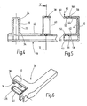
- the adapter 100 shown in Figures 4 to 6 in contrast to the adapter 10 is not rotatably held on the main bracket 12, but on the coupling portion 28 of the wiper arm.
- the adapter 100 has, in the region of its second contact section 36, which is U-shaped in cross-section, two latching lugs 56 projecting outwards.
- the locking lugs protrude in the assembled state, as can be seen in particular Figure 5, in the coupling portion 28 existing latching recesses 58.
- the coupling portion 28 shown in Figures 4 to 6 substantially corresponds to a coupling portion, as shown in FIG WO 00/73113 A1 has become known.
- actuating portions 60 are provided, which enable a disassembly of the adapter 100 from the coupling portion 28.
- the operating portions 60 are moved towards each other for disassembly in the direction of arrows 62.
- the latching lugs 56 pass out of the latching recesses 58, and the adapter 100 can be pivoted about the axis of the cylinder recess 24 or of the hinge pin 26 for release from the coupling section 28.
- the adapter 100 according to FIGS. 4, 5 and 6 has the advantage that when the wiper blade together with the adapter 100 is exchanged, all wearing parts are renewed. The coupling section 28 is then not subject to wear.
Landscapes
- Engineering & Computer Science (AREA)
- Mechanical Engineering (AREA)
- Pivots And Pivotal Connections (AREA)
- Dry Shavers And Clippers (AREA)
- Cleaning Implements For Floors, Carpets, Furniture, Walls, And The Like (AREA)
- Connector Housings Or Holding Contact Members (AREA)
Claims (14)
- Raccord (10, 100) permettant l'adaptation d'un étrier principal (12) d'un balai d'essuie-glace avec la section d'accouplement (28) d'un bras d'essuie-glace d'un dispositif d'essuie-glace,
comportant une cheville d'enfichage (22) maintenue à une extrémité pour l'introduction latérale dans une ouverture de réception (20) s'étendant transversalement par rapport à l'axe longitudinal du balai d'essuie-glace sur l'étrier principal (12),
comportant un évidement cylindrique (24) prévu sur la cheville d'enfichage (22), présentant une ouverture d'introduction (30) permettant de recevoir un axe d'articulation (26) de la section d'accouplement (28) du bras d'essuie-glace,
moyennant quoi, dans la zone de l'ouverture d'introduction (30), on prévoit une première section de positionnement (32), permettant de positionner la zone maintenant l'axe d'articulation (26), de la section d'accouplement (28),
caractérisé en ce que le raccord (10) présente une deuxième section de positionnement (36) disposée sur le côté opposé à l'ouverture d'introduction (30), qui permet de positionner la butée (38) d'un insert (40) recouvrant au moins par section le raccord (10, 100) à l'état monté de la section d'accouplement (28). - Raccord (10, 100) selon la revendication 1, caractérisé en ce que la première (32) et/ou la deuxième sections de positionnement (36) sont configurées en relief dans la direction transversale de telle sorte que, à l'état monté sur l'étrier principal (12), la face latérale (14, 16) respective de l'étrier principal (12) présente un élément en saillie.
- Raccord (10, 100) selon la revendication 1 ou 2, caractérisé en ce que la première section de positionnement (32) est disposée à une certaine distance de la deuxième section de positionnement (36) dans la direction longitudinale du balai d'essuie-glace.
- Raccord (10, 100) selon l'une quelconque des revendications 1, 2 ou 3, caractérisé en ce que l'évidement cylindrique (24) est configuré sous la forme d'un trou traversant ou d'un trou borgne.
- Raccord (10, 100) selon l'une quelconque des revendications précédentes, caractérisé en ce que la deuxième section de positionnement (36) présente au moins, à la manière d'un insert, une joue (44, 42), qui, à l'état monté, enveloppe au moins une paroi latérale (14, 16) de l'étrier principal (12), au moins dans certaines conditions.
- Raccord (10, 100) selon l'une quelconque des revendications précédentes, caractérisé en ce que la deuxième section de positionnement (36) est configurée sous forme de L ou de U en coupe.
- Raccord (10, 100) selon l'une quelconque des revendications précédentes, caractérisé en ce que la largeur dans la direction transversale de la deuxième section de positionnement (36), à l'état monté, est largement enveloppée par conjugaison de forme par l'insert et la butée (38, 40) de la section d'accouplement (28) du bras d'essuie-glace.
- Raccord (10, 100) selon l'une quelconque des revendications précédentes, caractérisé en ce que le raccord (10, 100) est maintenu de manière résistante à la rotation sur l'étrier principal (12) à l'état monté.
- Raccord (10, 100) selon l'une quelconque des revendications précédentes, caractérisé en ce que le raccord (10, 100) est maintenu de manière résistante à la rotation sur la section d'accouplement (28) du bras d'essuie-glace à l'état monté.
- Raccord (10, 100) selon l'une quelconque des revendications précédentes, caractérisé en ce que le raccord (10, 100) présente au moins une section d'encliquetage (48, 56) permettant l'encliquetage avec l'étrier principal (12) et/ou la section d'accouplement (28).
- Raccord (10, 100) selon l'une quelconque des revendications précédentes, caractérisé en ce que la section d'encliquetage ou les sections d'encliquetage (48, 56) sont disposées sur la deuxième section de positionnement (36).
- Raccord (10, 100) selon l'une quelconque des revendications précédentes, caractérisé en ce que la section d'encliquetage respectivement les sections d'encliquetage sont disposées sur l'extrémité libre (52) respectivement sur les extrémités libres des joues (42, 44) de la deuxième section de positionnement (36).
- Raccord (10, 100) selon l'une quelconque des revendications précédentes, caractérisé en ce que le raccord (10, 100) présente, entre la cheville d'enfichage (22) et la deuxième section de positionnement (36), une branche (42) s'étendant dans la direction longitudinale du balai d'essuie-glace qui repose, à l'état monté, au moins par section sur une paroi latérale (16) de l'étrier principal (12).
- Raccord (10, 100) selon la revendication 13, caractérisé en ce que la branche (42) ne dépasse pas des parois latérales de l'étrier principal (12).
Applications Claiming Priority (3)
| Application Number | Priority Date | Filing Date | Title |
|---|---|---|---|
| DE10251520 | 2002-11-04 | ||
| DE10251520A DE10251520A1 (de) | 2002-11-04 | 2002-11-04 | Adapter für ein Wischblatt |
| PCT/EP2003/012000 WO2004041605A1 (fr) | 2002-11-04 | 2003-10-29 | Adaptateur pour un balai d'essuie-glace |
Publications (2)
| Publication Number | Publication Date |
|---|---|
| EP1558476A1 EP1558476A1 (fr) | 2005-08-03 |
| EP1558476B1 true EP1558476B1 (fr) | 2007-08-08 |
Family
ID=32103354
Family Applications (1)
| Application Number | Title | Priority Date | Filing Date |
|---|---|---|---|
| EP03778293A Expired - Lifetime EP1558476B1 (fr) | 2002-11-04 | 2003-10-29 | Adaptateur pour un balai d'essuie-glace |
Country Status (8)
| Country | Link |
|---|---|
| US (1) | US7676881B2 (fr) |
| EP (1) | EP1558476B1 (fr) |
| CN (1) | CN100377935C (fr) |
| AT (1) | ATE369272T1 (fr) |
| AU (1) | AU2003285307A1 (fr) |
| DE (2) | DE10251520A1 (fr) |
| ES (1) | ES2291714T3 (fr) |
| WO (1) | WO2004041605A1 (fr) |
Families Citing this family (1)
| Publication number | Priority date | Publication date | Assignee | Title |
|---|---|---|---|---|
| ITMI20041965A1 (it) * | 2004-10-15 | 2005-01-15 | Augusto Amici | "dna codificante forme tronche e chimeriche della proteina p185neu e suoi usi terapeutici" |
Family Cites Families (13)
| Publication number | Priority date | Publication date | Assignee | Title |
|---|---|---|---|---|
| US4007511A (en) | 1975-04-07 | 1977-02-15 | Trico Products Corporation | Vehicle windshield wiper blade assemblies |
| US4132490A (en) | 1975-06-07 | 1979-01-02 | Paul Journee, S.A. | Device for securing a wiper blade to an arm |
| FR2324489A1 (fr) * | 1975-09-16 | 1977-04-15 | Journee Paul Sa | Dispositif de fixation d'un balai d'essuie-glace sur un bras |
| IT1144605B (it) * | 1981-06-09 | 1986-10-29 | Arman Spa | Dispositivo d attacco per tergicristalli |
| US4970751A (en) * | 1989-04-17 | 1990-11-20 | Tridon Limited | Adaptor for windshield wiper pin |
| US5715563A (en) * | 1996-11-04 | 1998-02-10 | Worktools, Inc. | Windshield wiper bracket |
| DE19838883A1 (de) * | 1998-08-27 | 2000-03-02 | Bosch Gmbh Robert | Vorrichtung zum Verbinden eines Wischblatts mit einem Wischerarm |
| HU226808B1 (en) * | 1999-05-28 | 2009-11-30 | Bosch Gmbh Robert | Wiper blade for the glass surfaces of a motor vehicle |
| DE19924662B4 (de) | 1999-05-28 | 2007-06-28 | Robert Bosch Gmbh | Wischvorrichtung für Scheiben von Kraftfahrzeugen |
| DE10100847A1 (de) * | 2001-01-05 | 2002-07-11 | Volkswagen Ag | Wischervorrichtung mit einem Anschlußelement zur Befestigung des Wischblatts an dem Wischerarm |
| DE10108200A1 (de) * | 2001-02-21 | 2002-08-22 | Bosch Gmbh Robert | Wischvorrichtung insbesondere für Scheiben von Kraftfahrzeugen |
| DE10162402B4 (de) * | 2001-12-19 | 2006-10-19 | Robert Bosch Gmbh | Wischblatt |
| DE102004017722A1 (de) * | 2004-04-10 | 2005-10-27 | Robert Bosch Gmbh | Adapter zum gelenkigen Verbinden eines Wischblatts mit einem Wischarm |
-
2002
- 2002-11-04 DE DE10251520A patent/DE10251520A1/de not_active Withdrawn
-
2003
- 2003-10-29 AT AT03778293T patent/ATE369272T1/de not_active IP Right Cessation
- 2003-10-29 WO PCT/EP2003/012000 patent/WO2004041605A1/fr not_active Ceased
- 2003-10-29 US US10/533,668 patent/US7676881B2/en not_active Expired - Fee Related
- 2003-10-29 AU AU2003285307A patent/AU2003285307A1/en not_active Abandoned
- 2003-10-29 ES ES03778293T patent/ES2291714T3/es not_active Expired - Lifetime
- 2003-10-29 EP EP03778293A patent/EP1558476B1/fr not_active Expired - Lifetime
- 2003-10-29 CN CNB2003801023617A patent/CN100377935C/zh not_active Expired - Fee Related
- 2003-10-29 DE DE50307904T patent/DE50307904D1/de not_active Expired - Lifetime
Non-Patent Citations (1)
| Title |
|---|
| None * |
Also Published As
| Publication number | Publication date |
|---|---|
| AU2003285307A1 (en) | 2004-06-07 |
| ATE369272T1 (de) | 2007-08-15 |
| CN100377935C (zh) | 2008-04-02 |
| CN1708428A (zh) | 2005-12-14 |
| DE10251520A1 (de) | 2004-05-13 |
| EP1558476A1 (fr) | 2005-08-03 |
| US20060143848A1 (en) | 2006-07-06 |
| ES2291714T3 (es) | 2008-03-01 |
| DE50307904D1 (de) | 2007-09-20 |
| US7676881B2 (en) | 2010-03-16 |
| WO2004041605A1 (fr) | 2004-05-21 |
Similar Documents
| Publication | Publication Date | Title |
|---|---|---|
| EP1565359B1 (fr) | Dispositif pour raccorder de maniere amovible un balai d'essuie-glace et un bras d'essuie-glace commandable | |
| EP2321160B1 (fr) | Dispositif de liaison articulée entre un balai d essuie-glace et un bras d essuie-glace | |
| EP2736775B1 (fr) | Dispositif de raccordement pour la liaison articulée d'une raclette à un porte-balais et un adaptateur | |
| EP1485280A1 (fr) | Dispositif d'essuie-glace comprenant un balai d'essuie-glace plat et un bras d'essuie-glace | |
| DE102008000708A1 (de) | Wischblatt | |
| DE10065014A1 (de) | Wischvorrichtung, insbesondere für Scheiben von Kraftfahrzeugen | |
| EP1056628A1 (fr) | Dispositif pour l'assemblage articule d'une raclette d'essuie-glace destinee aux vitres de vehicules automobiles avec un bras d'essuie-glace, et procede de realisation de cet assemblage | |
| EP1337420A1 (fr) | Levier d'essuie-glace comportant un bras d'essuie-glace entraine et une raclette d'essuie-glace articulee sur ledit bras pour le nettoyage de vitres, en particulier de vehicules automobiles | |
| WO2002052917A2 (fr) | Dispositif permettant de connecter de maniere amovible une raclette d'essuie-glace a un bras d'essuie-glace | |
| DE19857375A1 (de) | Wischervorrichtung | |
| DE10043427B4 (de) | Wischvorrichtung | |
| DE10230457B4 (de) | Anschlussvorrichtung für einen Scheibenwischer | |
| EP1824717B1 (fr) | Raclette d'essuie-glace | |
| EP1558476B1 (fr) | Adaptateur pour un balai d'essuie-glace | |
| EP0709267B1 (fr) | Dispositif d'essuie-glaces de véhicules automobiles | |
| DE8205994U1 (de) | Wischarm, insbesondere fuer scheibenwischeranlagen von kraftfahrzeugen | |
| EP2108552B1 (fr) | Essuie-glace, en particulier pour véhicules automobiles | |
| EP0966374A1 (fr) | Support d'articulation d'un balai d'essuie-glace | |
| WO2005002934A1 (fr) | Raccordement entre une raclette d'essuie-glace et un bras de monture d'essuie-glace d'un systeme d'essuie-glace pour vehicules a moteur, et systeme d'essuie-glace muni d'un tel raccordement | |
| DE102015011370A1 (de) | Wischblatt für eine Scheibenwischanlage eines Fahrzeugs und Verbindungsanordnung mit einem Wischblatt und einem Wischarm | |
| DE10040530A1 (de) | Wischvorrichtung, insbesondere für Kraftfahrzeuge | |
| DE10043426A1 (de) | Wischvorrichtung | |
| EP1567397A1 (fr) | Adaptateur pour balai d'essuie-glace | |
| EP1140587A1 (fr) | Assemblage articule | |
| DE10162402B4 (de) | Wischblatt |
Legal Events
| Date | Code | Title | Description |
|---|---|---|---|
| PUAI | Public reference made under article 153(3) epc to a published international application that has entered the european phase |
Free format text: ORIGINAL CODE: 0009012 |
|
| 17P | Request for examination filed |
Effective date: 20050425 |
|
| AK | Designated contracting states |
Kind code of ref document: A1 Designated state(s): AT BE BG CH CY CZ DE DK EE ES FI FR GB GR HU IE IT LI LU MC NL PT RO SE SI SK TR |
|
| AX | Request for extension of the european patent |
Extension state: AL LT LV MK |
|
| DAX | Request for extension of the european patent (deleted) | ||
| GRAP | Despatch of communication of intention to grant a patent |
Free format text: ORIGINAL CODE: EPIDOSNIGR1 |
|
| GRAS | Grant fee paid |
Free format text: ORIGINAL CODE: EPIDOSNIGR3 |
|
| GRAA | (expected) grant |
Free format text: ORIGINAL CODE: 0009210 |
|
| AK | Designated contracting states |
Kind code of ref document: B1 Designated state(s): AT BE BG CH CY CZ DE DK EE ES FI FR GB GR HU IE IT LI LU MC NL PT RO SE SI SK TR |
|
| REG | Reference to a national code |
Ref country code: GB Ref legal event code: FG4D Free format text: NOT ENGLISH |
|
| REG | Reference to a national code |
Ref country code: CH Ref legal event code: EP |
|
| REG | Reference to a national code |
Ref country code: IE Ref legal event code: FG4D Free format text: LANGUAGE OF EP DOCUMENT: GERMAN |
|
| REF | Corresponds to: |
Ref document number: 50307904 Country of ref document: DE Date of ref document: 20070920 Kind code of ref document: P |
|
| ET | Fr: translation filed | ||
| PG25 | Lapsed in a contracting state [announced via postgrant information from national office to epo] |
Ref country code: NL Free format text: LAPSE BECAUSE OF FAILURE TO SUBMIT A TRANSLATION OF THE DESCRIPTION OR TO PAY THE FEE WITHIN THE PRESCRIBED TIME-LIMIT Effective date: 20070808 Ref country code: BG Free format text: LAPSE BECAUSE OF FAILURE TO SUBMIT A TRANSLATION OF THE DESCRIPTION OR TO PAY THE FEE WITHIN THE PRESCRIBED TIME-LIMIT Effective date: 20071108 Ref country code: FI Free format text: LAPSE BECAUSE OF FAILURE TO SUBMIT A TRANSLATION OF THE DESCRIPTION OR TO PAY THE FEE WITHIN THE PRESCRIBED TIME-LIMIT Effective date: 20070808 |
|
| NLV1 | Nl: lapsed or annulled due to failure to fulfill the requirements of art. 29p and 29m of the patents act | ||
| REG | Reference to a national code |
Ref country code: ES Ref legal event code: FG2A Ref document number: 2291714 Country of ref document: ES Kind code of ref document: T3 |
|
| GBV | Gb: ep patent (uk) treated as always having been void in accordance with gb section 77(7)/1977 [no translation filed] |
Effective date: 20070808 |
|
| REG | Reference to a national code |
Ref country code: IE Ref legal event code: FD4D |
|
| PG25 | Lapsed in a contracting state [announced via postgrant information from national office to epo] |
Ref country code: GR Free format text: LAPSE BECAUSE OF FAILURE TO SUBMIT A TRANSLATION OF THE DESCRIPTION OR TO PAY THE FEE WITHIN THE PRESCRIBED TIME-LIMIT Effective date: 20071109 Ref country code: DK Free format text: LAPSE BECAUSE OF FAILURE TO SUBMIT A TRANSLATION OF THE DESCRIPTION OR TO PAY THE FEE WITHIN THE PRESCRIBED TIME-LIMIT Effective date: 20070808 |
|
| PGFP | Annual fee paid to national office [announced via postgrant information from national office to epo] |
Ref country code: GB Payment date: 20071016 Year of fee payment: 5 |
|
| PG25 | Lapsed in a contracting state [announced via postgrant information from national office to epo] |
Ref country code: GB Free format text: LAPSE BECAUSE OF FAILURE TO SUBMIT A TRANSLATION OF THE DESCRIPTION OR TO PAY THE FEE WITHIN THE PRESCRIBED TIME-LIMIT Effective date: 20070808 Ref country code: IE Free format text: LAPSE BECAUSE OF FAILURE TO SUBMIT A TRANSLATION OF THE DESCRIPTION OR TO PAY THE FEE WITHIN THE PRESCRIBED TIME-LIMIT Effective date: 20070808 Ref country code: MC Free format text: LAPSE BECAUSE OF NON-PAYMENT OF DUE FEES Effective date: 20071031 Ref country code: CZ Free format text: LAPSE BECAUSE OF FAILURE TO SUBMIT A TRANSLATION OF THE DESCRIPTION OR TO PAY THE FEE WITHIN THE PRESCRIBED TIME-LIMIT Effective date: 20070808 Ref country code: PT Free format text: LAPSE BECAUSE OF FAILURE TO SUBMIT A TRANSLATION OF THE DESCRIPTION OR TO PAY THE FEE WITHIN THE PRESCRIBED TIME-LIMIT Effective date: 20080108 Ref country code: SK Free format text: LAPSE BECAUSE OF FAILURE TO SUBMIT A TRANSLATION OF THE DESCRIPTION OR TO PAY THE FEE WITHIN THE PRESCRIBED TIME-LIMIT Effective date: 20070808 |
|
| PLBE | No opposition filed within time limit |
Free format text: ORIGINAL CODE: 0009261 |
|
| STAA | Information on the status of an ep patent application or granted ep patent |
Free format text: STATUS: NO OPPOSITION FILED WITHIN TIME LIMIT |
|
| REG | Reference to a national code |
Ref country code: CH Ref legal event code: PL |
|
| PG25 | Lapsed in a contracting state [announced via postgrant information from national office to epo] |
Ref country code: SE Free format text: LAPSE BECAUSE OF FAILURE TO SUBMIT A TRANSLATION OF THE DESCRIPTION OR TO PAY THE FEE WITHIN THE PRESCRIBED TIME-LIMIT Effective date: 20071108 Ref country code: RO Free format text: LAPSE BECAUSE OF FAILURE TO SUBMIT A TRANSLATION OF THE DESCRIPTION OR TO PAY THE FEE WITHIN THE PRESCRIBED TIME-LIMIT Effective date: 20070808 |
|
| 26N | No opposition filed |
Effective date: 20080509 |
|
| PG25 | Lapsed in a contracting state [announced via postgrant information from national office to epo] |
Ref country code: CH Free format text: LAPSE BECAUSE OF NON-PAYMENT OF DUE FEES Effective date: 20071031 Ref country code: LI Free format text: LAPSE BECAUSE OF NON-PAYMENT OF DUE FEES Effective date: 20071031 |
|
| PG25 | Lapsed in a contracting state [announced via postgrant information from national office to epo] |
Ref country code: EE Free format text: LAPSE BECAUSE OF FAILURE TO SUBMIT A TRANSLATION OF THE DESCRIPTION OR TO PAY THE FEE WITHIN THE PRESCRIBED TIME-LIMIT Effective date: 20070808 |
|
| PG25 | Lapsed in a contracting state [announced via postgrant information from national office to epo] |
Ref country code: AT Free format text: LAPSE BECAUSE OF NON-PAYMENT OF DUE FEES Effective date: 20071029 |
|
| PG25 | Lapsed in a contracting state [announced via postgrant information from national office to epo] |
Ref country code: SI Free format text: LAPSE BECAUSE OF FAILURE TO SUBMIT A TRANSLATION OF THE DESCRIPTION OR TO PAY THE FEE WITHIN THE PRESCRIBED TIME-LIMIT Effective date: 20070808 |
|
| PG25 | Lapsed in a contracting state [announced via postgrant information from national office to epo] |
Ref country code: CY Free format text: LAPSE BECAUSE OF FAILURE TO SUBMIT A TRANSLATION OF THE DESCRIPTION OR TO PAY THE FEE WITHIN THE PRESCRIBED TIME-LIMIT Effective date: 20070808 |
|
| PG25 | Lapsed in a contracting state [announced via postgrant information from national office to epo] |
Ref country code: LU Free format text: LAPSE BECAUSE OF NON-PAYMENT OF DUE FEES Effective date: 20071029 |
|
| PG25 | Lapsed in a contracting state [announced via postgrant information from national office to epo] |
Ref country code: TR Free format text: LAPSE BECAUSE OF FAILURE TO SUBMIT A TRANSLATION OF THE DESCRIPTION OR TO PAY THE FEE WITHIN THE PRESCRIBED TIME-LIMIT Effective date: 20070808 Ref country code: HU Free format text: LAPSE BECAUSE OF FAILURE TO SUBMIT A TRANSLATION OF THE DESCRIPTION OR TO PAY THE FEE WITHIN THE PRESCRIBED TIME-LIMIT Effective date: 20080209 |
|
| REG | Reference to a national code |
Ref country code: FR Ref legal event code: PLFP Year of fee payment: 13 |
|
| REG | Reference to a national code |
Ref country code: FR Ref legal event code: PLFP Year of fee payment: 14 |
|
| PGFP | Annual fee paid to national office [announced via postgrant information from national office to epo] |
Ref country code: ES Payment date: 20161027 Year of fee payment: 14 Ref country code: IT Payment date: 20161011 Year of fee payment: 14 Ref country code: BE Payment date: 20161027 Year of fee payment: 14 |
|
| REG | Reference to a national code |
Ref country code: FR Ref legal event code: PLFP Year of fee payment: 15 |
|
| REG | Reference to a national code |
Ref country code: BE Ref legal event code: MM Effective date: 20171031 |
|
| PG25 | Lapsed in a contracting state [announced via postgrant information from national office to epo] |
Ref country code: BE Free format text: LAPSE BECAUSE OF NON-PAYMENT OF DUE FEES Effective date: 20171031 |
|
| REG | Reference to a national code |
Ref country code: FR Ref legal event code: PLFP Year of fee payment: 16 |
|
| PG25 | Lapsed in a contracting state [announced via postgrant information from national office to epo] |
Ref country code: IT Free format text: LAPSE BECAUSE OF NON-PAYMENT OF DUE FEES Effective date: 20171029 |
|
| REG | Reference to a national code |
Ref country code: ES Ref legal event code: FD2A Effective date: 20181221 |
|
| PG25 | Lapsed in a contracting state [announced via postgrant information from national office to epo] |
Ref country code: ES Free format text: LAPSE BECAUSE OF NON-PAYMENT OF DUE FEES Effective date: 20171030 |
|
| PGFP | Annual fee paid to national office [announced via postgrant information from national office to epo] |
Ref country code: DE Payment date: 20191009 Year of fee payment: 17 |
|
| PGFP | Annual fee paid to national office [announced via postgrant information from national office to epo] |
Ref country code: FR Payment date: 20191031 Year of fee payment: 17 |
|
| REG | Reference to a national code |
Ref country code: DE Ref legal event code: R119 Ref document number: 50307904 Country of ref document: DE |
|
| PG25 | Lapsed in a contracting state [announced via postgrant information from national office to epo] |
Ref country code: FR Free format text: LAPSE BECAUSE OF NON-PAYMENT OF DUE FEES Effective date: 20201031 Ref country code: DE Free format text: LAPSE BECAUSE OF NON-PAYMENT OF DUE FEES Effective date: 20210501 |