EP1558434B1 - Procede et dispositif pour le traitement ulterieur et le refroidissement de preformes - Google Patents
Procede et dispositif pour le traitement ulterieur et le refroidissement de preformes Download PDFInfo
- Publication number
- EP1558434B1 EP1558434B1 EP03702261A EP03702261A EP1558434B1 EP 1558434 B1 EP1558434 B1 EP 1558434B1 EP 03702261 A EP03702261 A EP 03702261A EP 03702261 A EP03702261 A EP 03702261A EP 1558434 B1 EP1558434 B1 EP 1558434B1
- Authority
- EP
- European Patent Office
- Prior art keywords
- cooling
- preforms
- removal
- preform
- injection moulding
- Prior art date
- Legal status (The legal status is an assumption and is not a legal conclusion. Google has not performed a legal analysis and makes no representation as to the accuracy of the status listed.)
- Expired - Lifetime
Links
Images


Classifications
-
- B—PERFORMING OPERATIONS; TRANSPORTING
- B29—WORKING OF PLASTICS; WORKING OF SUBSTANCES IN A PLASTIC STATE IN GENERAL
- B29C—SHAPING OR JOINING OF PLASTICS; SHAPING OF MATERIAL IN A PLASTIC STATE, NOT OTHERWISE PROVIDED FOR; AFTER-TREATMENT OF THE SHAPED PRODUCTS, e.g. REPAIRING
- B29C45/00—Injection moulding, i.e. forcing the required volume of moulding material through a nozzle into a closed mould; Apparatus therefor
- B29C45/17—Component parts, details or accessories; Auxiliary operations
- B29C45/72—Heating or cooling
- B29C45/7207—Heating or cooling of the moulded articles
- B29C2045/7214—Preform carriers for cooling preforms
-
- B—PERFORMING OPERATIONS; TRANSPORTING
- B29—WORKING OF PLASTICS; WORKING OF SUBSTANCES IN A PLASTIC STATE IN GENERAL
- B29C—SHAPING OR JOINING OF PLASTICS; SHAPING OF MATERIAL IN A PLASTIC STATE, NOT OTHERWISE PROVIDED FOR; AFTER-TREATMENT OF THE SHAPED PRODUCTS, e.g. REPAIRING
- B29C49/00—Blow-moulding, i.e. blowing a preform or parison to a desired shape within a mould; Apparatus therefor
- B29C49/42—Component parts, details or accessories; Auxiliary operations
- B29C49/4242—Means for deforming the parison prior to the blowing operation
- B29C49/42421—Means for deforming the parison prior to the blowing operation before laying into the mould
-
- B—PERFORMING OPERATIONS; TRANSPORTING
- B29—WORKING OF PLASTICS; WORKING OF SUBSTANCES IN A PLASTIC STATE IN GENERAL
- B29C—SHAPING OR JOINING OF PLASTICS; SHAPING OF MATERIAL IN A PLASTIC STATE, NOT OTHERWISE PROVIDED FOR; AFTER-TREATMENT OF THE SHAPED PRODUCTS, e.g. REPAIRING
- B29C49/00—Blow-moulding, i.e. blowing a preform or parison to a desired shape within a mould; Apparatus therefor
- B29C49/42—Component parts, details or accessories; Auxiliary operations
- B29C49/64—Heating or cooling preforms, parisons or blown articles
- B29C49/6409—Thermal conditioning of preforms
- B29C49/6427—Cooling of preforms
-
- B—PERFORMING OPERATIONS; TRANSPORTING
- B29—WORKING OF PLASTICS; WORKING OF SUBSTANCES IN A PLASTIC STATE IN GENERAL
- B29K—INDEXING SCHEME ASSOCIATED WITH SUBCLASSES B29B, B29C OR B29D, RELATING TO MOULDING MATERIALS OR TO MATERIALS FOR MOULDS, REINFORCEMENTS, FILLERS OR PREFORMED PARTS, e.g. INSERTS
- B29K2105/00—Condition, form or state of moulded material or of the material to be shaped
- B29K2105/25—Solid
- B29K2105/253—Preform
Definitions
- the invention relates to a method for aftercooling of preforms after removal from the open mold halves of an injection molding machine, wherein the preforms are removed in a still hot state by means of a removal device from the open molds and cooled in controllable phases by means of water-cooled cooling sleeves, wherein the preforms in a removal phase "A" removed directly from the open molds and the cooling sleeves are introduced and, in a phase "B” subjected to intensive cooling and then fully cooled in a Nachksselphase, which is a multiple of the injection cycle time.
- the invention further relates to a device for aftercooling of preforms after their removal from the open mold halves of an injection molding machine, which aids for repelling the semi-rigid preforms of the part molds and a Nachkühlung the preforms in a removal station and a Nachkühl responded by means of water-cooled cooling sleeves and Blasdorne, wherein the removal station has a removal device with horizontally arranged cooling sleeves, which are assigned to the preforms insertable mandrels, and the device has a controller for controlling all movements for handling the preforms and the mandrels and for the use of compressed air and optionally suction air.
- the cooling time is a determining factor for the total time of a full cycle.
- the main cooling performance still takes place in the mold halves.
- Both mold halves are intensively water-cooled during the casting process, so that the temperature of the injection-molded parts can still be reduced in the form of about 280 ° C, at least in the outer layers to a range of 70 ° C to 120 ° C. It is in the outer layers very quickly pass through the so-called glass transition temperature of about 140 ° C.
- the actual casting process up to the removal of the injection molding parts has been reduced in the recent past in the case of the production of thick-walled preforms to about 12 to 15 seconds and thin-walled preforms to less than 10 seconds become.
- the preforms must be so strongly solidified in the mold halves that they can be handled with relatively large forces by the ejection aids and transferred without deformation or damage to a removal device.
- the removal device has a shape adapted to the dimensions of the injection molded parts.
- the intensive water cooling in the mold halves takes place especially with large wall thicknesses from the outside to the inside, due to physical reasons, strongly delayed in time. This means that the said 70 ° C to 120 ° C are not uniformly achieved in the entire cross section. The consequence is that seen in the material cross-section, a rapid re-heating, from the inside out; as soon as the intensive water cooling is interrupted by the molds. Aftercooling is of great importance for two reasons.
- the U.S. Patent 4,592,719 proposes to increase the production rate of the preforms by using atmospheric air for cooling.
- the air is used as cooling air during transport or "handling" by targeted flow guidance, both inside and outside, on the preforms with maximum cooling effect.
- a sampling device which has as many suction pipes as parts are produced in a molding cycle, enters between the two open mold halves. The suction pipes are then pushed over the preforms. At the same time, air begins to flow through a suction line in the area of the entire circumference surface of each blow molded part encompassed by the intake pipes, so that they are cooled from the moment they are taken into the suction sleeve with the air from outside.
- the removal device moves out after complete adoption of all injection molded parts of a Giesszyklusses from the range of motion of the mold halves.
- the mold halves are immediately free again and are closed again for the subsequent casting cycle.
- the removal device pivots the preforms after the extension movement from a horizontal to an upright position.
- a transfer device moves exactly into a transfer position above the removal device.
- the transfer device has an equal number of internal grippers, as the removal device has suction tubes.
- the removal device is pivoted back into the retracted position, so that the next batch of injection molded parts can be removed from the molds.
- the transfer device transfers the injection molded parts to a conveyor and moves without the preforms back to the transfer position for the next batch.
- the EP 0 947 304 had the task to improve the cooling efficiency and the quality of the preforms and to shorten the overall cycle time.
- the document primarily describes the problem of crystal formation with poor guidance of aftercooling. It is proposed to primarily cool the inner compartment with air by means of a controlled and positively guided tuyere, the cooling insert being made immediately after removal of the preforms from the open halves of the mold and thus preventing local crystallization.
- the U.S. Patent 6,332,770 (Husky ) solves the same problem as the one EP 0 947 304 but by cooling by a local effect via convection cooling.
- An internally cooled mandrel is inserted into the inner dome area.
- the division of the preforms is treated by convective cooling.
- the major disadvantage of the proposal with the convective contact cooling by means of a mandrel insertable into the preform is the problem of precise, mechanically forced introduction of the mandrel to the production of a contact with each relevant inner wall surface of the preforms and especially the required precision for the introduction of 100 and more thorns.
- the entire machine with all movements must be designed with the utmost precision, so that every single preform is contacted equally and without pressure damage.
- the internal cooling takes place via the blowing mandrels, which have a blast air channel inside.
- the relative movement for the introduction of Blasdorne takes place forcibly by a removal robot.
- the blowing mandrels have at first a blowing air opening.
- the blast air jet is directed directly perpendicular to the dome-shaped bottom of the preforms and can then be guided in the opposite direction along the inner wall of the preform and freely flow out at the open end of the preform.
- the object of the new invention was to optimize the cooling with regard to a shortened injection molding cycle time with as high a quality as possible and with the smallest possible amount of crystallization of the preforms, without major procedural expenses or additional costs for the production of the injection molding machine.
- the invention is solved by a method according to claim 1 and a device according to claim 6.
- the first aftercooling phase is particularly sensitive, since the preforms are still insufficiently dimensionally stable.
- the danger that the blow molded part "bends" slightly with respect to the threaded part from the thread axis is actually a real problem in the phase of removing the preform in a lying position in horizontally operating injection molding machines. This is especially true when the cooling time within the injection molds is kept to a minimum and the preforms are still relatively hot and correspondingly soft. If the preforms are in a lying position during the first phase of the aftercooling, then they tend to hang down on the corresponding cooling sleeve part.
- the new invention is based primarily on the cooling concept, in which the individual preforms are introduced in the aftercooling only with the blow molded in cooling sleeves.
- the threaded parts project beyond the cooling sleeves.
- the new solution suggests optimal contact with the cooling sleeve, especially in the phase of intensive cooling immediately after removal from the casting molds, thereby achieving a short, maximum intensified temperature reduction and stabilization of the preforms in the first post-cooling phase for the subsequent final cooling.
- the dynamic introduction of the preforms to the complete wall contact in the cooling sleeves, directly after the removal of the preforms from the molds, but before the prolonged pre-cooling, has decisive advantages:
- the cooling effect is, for physical reasons, at the greatest temperature difference between hot preforms and cooling sleeves directly after removal from the molds largest.
- the forced, rich and full-surface concerns of the preforms to the inner surface of the cooling sleeves results in the greatest possible profit by maximizing the direct heat conduction.
- the formation of crystalline fractions is thus reduced to a minimum. They are still hot Preforms are pushed into a cooling mold with the least possible play immediately after their removal from the molds to maintain the dimensional accuracy.
- the rapidly cooled preform after removal thus retains its shape accuracy during subsequent handling with respect to symmetry.
- the cooling sleeve is selected in the inner diameter at most by a few hundredths of a millimeter larger than the outer dimensions of the still hot preforms.
- a swelling pressure can be generated and the preform be brought to complete concern to the entire inner wall surface of the cooling sleeve.
- the surface contact is maintained for several seconds, thereby maximizing the cooling effect.
- a calibration effect is generated for each individual preform. The calibration effect gives the possibility of a production and quality standard in the production of preforms, as it was not possible in the context of the prior art.
- the preforms are pressed shortly after removal from the molds again in an exact shape, so that any dimensional changes after the first critical handling of the molds in the cooling sleeves, in particular a bending of the preforms can be turned off by one-sided resting in the cooling sleeve.
- the calibration effect allows the preforms to be removed even earlier from the molds, thereby achieving an even shorter casting cycle time, as well as an improved first phase of aftercooling. This is very advantageous especially with regard to the fastest possible passage through the glass transition temperature and thus the harmful crystal formation.
- the subsequent after-cooling can be carried out more problem-free with respect to all qualitative parameters in the required time, produces preforms of the highest quality and at the same time increases the productivity of the injection molding machine.
- the invention allows a number of advantageous embodiments. Reference is made to the claims 2 to 5 and 7 to 15 reference.
- the cooling insert is stepped during intensive cooling.
- the remaining temperature differences in the preform are removed as soon as possible after removal from the molds.
- the intensive cooling is only a fraction of the total aftercooling. During the intensive cooling, the temperature is lowered on average by 20 ° C to 40 ° C. A strong prolongation of the intensive cooling phase is not advantageous because the heat migration within the preform material can not be increased.
- the blowing mandrels have a base formed as a shell, which has on the one hand Ausblasö Maschinenen for cooling air and on the other hand via the support plate with a compressed air source is connected, wherein the jacket is preferably guided over less than half the length of the suction tube.
- the carrier plate is formed with two chambers, a first chamber connected to a vacuum source and a second chamber connected to a compressed air source, wherein the suction pipe passed through the second chamber and the first chamber directly connected to the space between the jacket and the suction tube is.
- the suction air as well as for the blown air controllable valves are arranged, so that the temporal use can be optimized.
- the new solution has a removal device with cooling sleeves and a movable to a sealing closure support plate of the transfer gripper with a Cooling air connection on.
- the support plate is equipped with bladders according to the number of cooling sleeves with sealing rings, which form a sealing point for each preform in Preforminneren to generate a slight inflation pressure in the interior of the preforms.
- the sealing point is arranged with respect to the open end of the preforms and acts only at the end of the insertion movement of the blowing mandrels.
- the sealing point between the individual blowing mandrels and the outer edge of the threaded portion of the preforms is made by a soft seal and the edge of the threaded portion held over the elastic seal.
- a third embodiment is characterized in that the device for internal cooling in the preforms insertable mandrels of a controllably displaceable support plate, wherein the individual mandrels are formed with respect to the preforms in the direction of insertion movement, such that each mandrel with controlled force until to the contact of the inner Dompartie the preforms is insertable.
- the blowing mandrels may have a contact head arranged displaceably and an air bore guided continuously up to the contact head, which opens into a blowing air chamber which can be changed in size between the mandrel and the contact head.
- each mandrel for generating a controlled pressing force on a compression spring may have a contact head arranged displaceably and an air bore guided continuously up to the contact head, which opens into a blowing air chamber which can be changed in size between the mandrel and the contact head.
- the blowing mandrels are formed with a contact cooling head, for mechanical contacting and contact cooling of the corresponding inner Dompartie of the respective preform, wherein the controlled force can be generated by blowing air and / or by a compression spring.
- the contact head is preferably arranged sleeve-like manner on the mandrel between a maximally pushed-out and tightened position freely displaceable.
- each mandrel has a slidably disposed contact head.
- a blowing air bore which is guided continuously up to the contact head is provided which opens into a blow-air chamber which can be changed in size.
- Each contact head is sleeve-like arranged freely displaceable on the mandrel between a maximally pushed-out and tightened position, wherein the ejected position can be produced by the blowing air and / or a compression spring and the tightened position by negative pressure.
- the contact heads may have in the region of the contact tip at least one blown air opening, which are connected to the blown air chamber.
- the contact tip can be formed closed in the sprue area of the preform for purely mechanical contacting of the corresponding innermost part of the Dompartie of the respective preform.
- Each mandrel advantageously has a fixable on the support plate Blasdornsockel with a tubular extension in Blas Kunststoffraum on, wherein the contact head relative to the tubular extension is displaceable.
- the contact head and the mandrel base are at least approximately cylindrical in shape, such that between the cylindrical forms and the Preforminnenseite forms a bottleneck with increased speed for the outflowing blast air.
- transverse bores can be arranged, which can be connected to a vacuum source to ensure safe removal of the preforms from the cooling sleeves and a transfer to the actual aftercooler.
- the new solution has a Nachkühlstation and an intensive cooling station, wherein in the intensive cooling station both the Preforminnenseite as the Preformaussenseite within the time of Spritzgiesszyklusses is intensively coolable.
- the intensive cooling station can be designed as a structurally independently controllable removal station or as part of an aftercooler, which has a quantity of cooling sleeves, corresponding to several batches of an injection molding cycle, particularly preferably four batches.
- the entire aftercooling has a control to control all movements for the handling of the preforms and the mandrels and for a cyclically timed use of compressed air and suction air, also a removal robot with cooling sleeves, a transfer gripper with the support plate with controllable movements with respect to the mandrels, wherein the preforms are transferable by the transfer gripper after intensive cooling in the cooling sleeves of the removal robot to the aftercooler for complete cooling.
- a further advantageous embodiment is characterized in that the outer water-cooled cooling sleeves have an inner shape which corresponds to the inclusion of the curved bottom part of the outer mold of the preform and the cooling sleeve is formed with the inclusion of the curved bottom part as thin as possible, so that over the entire cooling sleeve and from the cooling sleeve on the Preformaussenseite by the short-term concerns a maximum heat transfer or heat transfer is made.
- the casting cycle lasts 10 to 15 seconds and the total cycle including the entire after-cooling takes 30 to 60 seconds.
- the performance of the machine is determined by the casting cycle time.
- the calibration takes place during the first phase of the after-cooling, whereby in a first phase compressed air of 1 to 10 bar is injected.
- the cooling of the preforms from the removal from the mold halves is not interrupted until the final cooling.
- the blowing mandrels have a sealing ring made of soft rubber. In this way it is ensured that act on the threaded portion no deformation forces.
- a local cooling and solidification of the surface is also generated during retraction of the blowing mandrels, which is directed in a first phase to the open threaded end and the bottom part of the preform.
- FIG. 1 shows the main steps for handling the preforms. From the position "B" , the sleeve-shaped preforms 10 arranged vertically one above the other are taken over by the transfer gripper 12 and 12 'and, by pivoting the transfer device 12 in the direction of the arrow P, into a position, horizontally next to one another, according to phase "C" ,
- the transfer gripper 12 consists of a pivotable about an axis 13 holding arm 14 which carries a holding plate 15, to the parallel spacing a support plate 16 is arranged for the blowing mandrels 22.
- the support plate 16 is by means of two controllable and controllable servomotors 17 and 18 according to arrow parallel to Retaining plate 15 can be raised, so that in the position "B" the sleeve-shaped injection molded parts 10 can be retrieved from the removal device 11 and pushed into the position in the "C" position in the overlying Nachkühl interference 19.
- the respective transfer takes place by increasing the distance between the holding plate 15 and the support plate 16.
- the more than 70 ° C warm preforms 10 are ready-cooled in the Nachkssel issued 19 and then, after a displacement of the Nachkssel designed 19, in the position "D" expelled and thrown on a conveyor belt 20.
- the pivoting movement of the transfer gripper, the linear loading movement for the insertion of the blowing mandrels and the transverse and longitudinal displacement of the Nachkühl founded on the electric servo drive so that each movement is controllable both in terms of time and with respect to the path with high accuracy.
- the servo motors can be controlled both in terms of travel and speed as well as the force to be built, so that the handling and especially the insertion movement can be performed with the highest fineness and accuracy.
- the removal device 11 is in dashed representation in a waiting position, whereby the end of the injection phase is indicated.
- the reference numeral 30 is the water cooling with corresponding supply and discharge lines, which are shown for simplicity with arrows and are assumed to be known.
- the reference numeral 31/32 denotes the air side, wherein 31 for injection resp. Compressed air supply and 32 for vacuum resp. Air suction stands.
- the preforms are simultaneously cooled internally and externally during the injection cycle. In the cooling sleeves of the removal device 11, only an external cooling takes place at first.
- the aftercooling device 19 can be moved horizontally independently from a pickup position to a dropping position (shown by dashed lines).
- the aftercooler 19 has a multiple of capacity compared to the number of cavities in the injection mold halves.
- the discharge of the finished cooled preforms 10 is thus carried out only after two, three or more injection molding cycles, so that correspondingly the after-cooling time is extended relative to the casting cycle.
- the transfer gripper 12 to the post-cooler 19 the latter can also be moved transversely and set in the appropriate position.
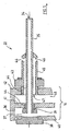
- FIGS. 2 and 3 two situations with the respective cooling engagement means are also shown schematically.
- the FIG. 2 shows the beginning of the removal of the preform 10 from the mold halves. Not shown are the tools for the rejection of semi-rigid preforms of the part forms 8 '.
- the support plate 16 with the blowing mandrels 22 is in the retracted position.
- FIG. 3 a situation for the core function of the new solution.
- the transfer gripper 12 is in the position according to FIG. 2 However, wherein the support plate 16 is shown with the Blasdornen 22 in the extended position.
- blowing mandrels 22 are completely inserted into the cooling sleeves 21, while the preforms are cooled intensively in the cooling sleeves.
- the remainder of the aftercooling takes place only in the aftercooler, after the preforms are dimensionally stabilized by the transfer gripper removed from the sampling device and introduced into the aftercooler.
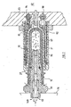
- the FIG. 4 shows the phase of intensive cooling. As an example, only five cooling positions are shown.
- the preforms 10 are cooled both externally and internally. The preforms are held in this phase permanently to the inner bottom part of the cooling sleeves by negative pressure in the space 23 of the removal device 11 or tightened.
- the FIG. 4 shows the use of blown air and suction air via two separate air systems. As an example, only five cooling positions are shown.
- the preforms 10 are cooled both externally and internally.
- the preforms are held in this phase permanently to the inner bottom part of the cooling sleeves by negative pressure in the space 42 of the removal device 11 or tightened.
- the space 23 can be switched as required by valves 24/25 of negative pressure to positive pressure.
- the FIG. 5 shows a blow pin 22 on a larger scale.
- the concept of the cooling pin is based on the assumption that cooling air is extracted at the mouth 34 of a suction pipe 35.
- the suction tube 35 is connected to a vacuum chamber 36 of the support plate 16 via a connection opening 37.
- the suction tube 35 is guided into a sealing screw 38 and sealed by an O-ring 39.
- the support plate 16 is shadowed with a rear wall 40, a middle wall 41 and a front wall 42.
- the vacuum chamber 36 is formed by the rear wall 40 and the middle wall 41.
- the sealing screw 38 is screwed with a thread 44 fixed in the middle wall 41.
- the mandrel 22 is screwed via a cooling pin base 43 and a thread 44 in the front wall 42 and has a jacket 45 with blow holes 46.
- Between coat 45 and the suction pipe 35 is an annular air channel 49 which is connected in the threaded portion via an opening 47 with a pressure chamber 48, so that compressed air via the pressure chamber 48, the opening 47, the annular space 29 and the blowing openings 46 can be blown into the preform interior.
- the pressure chamber 48 is limited by the middle wall 41 and the front wall 42nd
- a blow pin 22 is shown.
- a screw thread 50 by means of which the blowing mandrels 22 are screwed to the support plate 16.
- the support plate 16 has a larger number of nozzles 22, which are each arranged in a plurality of rows.
- two air systems 52 and 53 are arranged, wherein the air system 52 is designed for vacuum and the air system 53 for compressed air with corresponding, not shown, connections for a compressed air generator or a vacuum blower or a vacuum pump.
- the Saugluftitati 61 passes through an annular channel 62 and a plurality of transverse bores 63, which connect the annular channel 62 to the outside close to the sealing ring 60. As a result, air can be blown out via the blowing orifice 64 and drawn in again via the transverse bores 63.
- Flexible and pressure-resistant air hoses 31 and 32 provide the connection to the corresponding compressed air or suction air generators ( FIG. 1 ).
- the air hoses are designed for high pressure and vacuum.
- the entire air system has tube-like connections, which is optimal for the strength issue, both for the high pressure and negative pressure.
- Reference numeral 65 denotes the centering base of the blowing mandrels 22. Die FIG.
- FIG. 6a shows an end portion of the support plate 16 with a screwed-in air nozzle 66.
- the outer diameter DB on the cooling mandrel 22 is slightly smaller than the corresponding inner diameter of the preform 10. This results, supported by the air flow forces, a centering effect for the preform 10 on the tuyeres 22nd ,
- FIG. 6d shows the tuyere in the working position during calibration and the FIG. 6c a preform on average.
- the blow molding 71 has three sections: a neck portion 72, a conical portion 73, and a cylindrical portion 74.
- the neck portion 72 has a substantially smaller wall thickness Ws-2 relative to the cylindrical portion 74 having a wall thickness Ws-1.
- the wall material of the blow-molded part becomes necessary for the enormous enlargement in the blowing process or in the production of PET bottles.
- the tuyere 22 has an annular groove 75 into which a sealing ring 76 is inserted.
- FIG. 6d shows the tuyere 22 in calibration position.
- a gap 79 remains between the shoulder 77 and the edge 78 of the open preform side.
- the sealing ring 76 rests in the conical region 73 on the inner wall of the preform 10 and forms the sealing point 80.
- the sealing point 80 divides the preform inner part into two sections: one front pressure chamber 81 and a rear cooling chamber 82nd
- FIG. 7 shows the situation in the calibration of a preform 10 while external cooling in cooling sleeves according to the embodiment of FIGS. 6a to 6d ,
- the rear refrigerator 82 is indicated with + sign that for the calibration of an overpressure is made.
- the preform insofar as it is located in the cooling sleeve 21, has direct wall contact. This is especially true for the whole bottom part of the preform and the inner bottom part of the cooling sleeve.
- FIG. 8 shows a solution which is particularly in two areas of the solution according to FIG. 7 different.
- the tuyere 22 has a seal 90, 90 ', 90 ", which rises up on the edge 78 and forms the sealing point at the relevant point At the same time, the bottom area 83 is pushed against the arched inner bottom part 91 of the cooling sleeve
- the cooling sleeve 21 has a thin-walled design This is especially true for the dome-like bottom part 91.
- the dome-like bottom part 91 has a neck piece 92, which in one
- the cooling water 30 is introduced via a feed channel 94 into an inner cooling chamber 95, flows along the outer wall surface of the cooling sleeve 21 and leaves it via an opening 96 via an outer cooling chamber 96 and via the return channel 98.
- the air system is designed as a closed system is blown into the interior of the preform 10 via a blow pipe 57 and a Blasmündung 64 of the tuyere. The air is sucked through transverse bores 63 and an annular channel 62 by a vacuum source, not shown. Both sides can be finely tuned by exact control of movements and forces, both mechanical and air forces, especially in the most critical phase of the beginning of calibration with fully inserted preforms.
Claims (15)
- Procédé pour le refroidissement ultérieur de préformes (10) après le prélèvement hors des moitiés de moule ouvertes (8, 9) d'une machine de moulage par injection, dans lequel les préformes (10) sont prélevées des moitiés de moule ouvertes (8, 9) à l'état encore chaud via un dispositif de prélèvement avec des douilles de refroidissement (21) refroidies par eau et sont refroidies par phases pouvant être commandées, sachant que le dispositif de prélèvement (11) est mobile entre les moules ouverts (8, 9), sachant que les préformes sont prélevées dans une phase de prélèvement « A » directement des moules de coulée ouverts (8, 9) et sont introduites de manière dynamique dans les douilles de refroidissement (21) et soumises dans une phase « B » à un refroidissement intensif qui inclut la face intérieure et également extérieure d'une pièce moulée par soufflage des préformes (10) et sont ensuite complètement refroidies dans une phase de refroidissement ultérieur qui fait plusieurs fois la durée de cycle d'injection,
caractérisé en ce que
les préformes (10), peu après la phase de prélèvement « A » dans les douilles de refroidissement (21) dont le diamètre intérieur est choisi supérieur aux dimensions extérieures des préformes encore chaudes, sont placées, via une pression de soufflage produite par une commande ciblée d'air comprimé et d'air d'aspiration, complètement sur la surface de paroi intérieure des douilles de refroidissement (21) du dispositif de prélèvement (11) et amenées encore une fois dans une forme exacte, et en ce qu'un calibrage des préformes (10) est effectué via la pression de soufflage et un refroidissement intensif pendant la phase « B ». - Procédé selon la revendication 1, caractérisé en ce que le déplacement de tuyères de soufflage (22) est cadencé de manière temporelle dans le rythme du cycle de moulage par injection et le mouvement d'introduction est commandé à distance et/ou par force.
- Procédé selon la revendication 1 ou 2, caractérisé en ce que chaque tuyère de soufflage (22) est placée en étanchéité par rapport à la préforme respective (10) et que de l'air de soufflage ou d'aspiration est commandé de façon à ce que pendant le refroidissement intensif, une surpression soit produite dans chaque préforme (10) et que la préforme (10) soit comprimée sur la paroi intérieure du manchon de refroidissement (21) et en soit calibrée.
- Procédé selon la revendication 1, caractérisé en ce que la tuyère de soufflage (22) est entourée d'une enveloppe gonflable (150), sachant qu'à l'intérieur de l'enveloppe (150), un liquide de refroidissement respectivement sous pression circule pour calibrer et refroidir la préforme (10).
- Procédé selon l'une des revendications 1 à 4, caractérisé en ce que l'introduction dynamique dans le dispositif de prélèvement (11) s'effectue par la production commandée d'une dépression sur les côtés des douilles de refroidissement (21), respectivement sur les fonds extérieurs des préformes (84), et le prélèvement hors du dispositif de prélèvement (11) par le passage à la surpression sur les fonds extérieurs des préformes (84).
- Système de moulage par injection comprenant des parties de moule (8', 9') et un dispositif, en particulier pour exécuter un procédé selon la revendication 1, pour le refroidissement ultérieur de préformes (10) après leur prélèvement hors des moitiés de moule ouvertes (8, 9) d'une machine de moulage par injection, lequel dispositif comprend des moyens pour repousser les préformes semi-rigides (10) des parties de moule (8', 9') et présente un refroidissement ultérieur des préformes (10) dans un poste de prélèvement ainsi que dans un dispositif de refroidissement ultérieur (19) présentant une contenance multiple par rapport au nombre de cavités dans une moitié de moule de moulage par injection, sachant que le poste de prélèvement présente un dispositif de prélèvement (11) avec des douilles de refroidissement (21) refroidies par eau disposées horizontalement, auxquelles sont attribuées des tuyères de soufflage (22) pouvant être introduites dans les préformes (10), sachant que le dispositif de prélèvement (11) est mobile entre les moules ouverts, et le dispositif présente une commande pour commander tous les mouvements de manipulation des préformes (10) et des tuyères de soufflage (22) ainsi que pour un emploi d'air comprimé et le cas échéant, d'air d'aspiration,
caractérisé en ce que
la forme intérieure des douilles de refroidissement (21) disposées horizontalement du dispositif de prélèvement (11) est ainsi ajustée à la forme intérieure correspondante de la partie de moule (9') que le diamètre intérieur des douilles de refroidissement (21) est choisi supérieur aux dimensions extérieures des préformes encore chaudes et que les préformes (10), directement après le prélèvement hors des moules d'injection (8, 9), pour un refroidissement rapide de la face extérieure des préformes, peuvent être introduites de manière dynamique par un mouvement linéaire jusqu'à reposer de toute leur surface sur les douilles de refroidissement (21) refroidies par eau et peuvent à nouveau être amenées dans une forme exacte, sachant que le dispositif de prélèvement (11) est conçu en tant que poste de refroidissement intensif dans lequel les préformes (10) peuvent être soumises à une phase de calibrage ainsi qu'à une phase de refroidissement intensif, sachant que via les tuyères de soufflage (22), une pression de soufflage peut être produite par une commande ciblée d'air comprimé et d'air d'aspiration, de façon à ce que les préformes (10), via la pression de soufflage, puissent être placées complètement sur la surface de paroi intérieure des douilles de refroidissement (21) refroidies par eau, et sachant que la phase de refroidissement intensif inclut la face intérieure et également extérieure d'une pièce moulée par soufflage des préformes (10). - Système de moulage par injection selon la revendication 6,
caractérisé en ce que chaque tuyère de soufflage (22) présente une enveloppe formée comme un socle (100) qui peut être reliée à une source d'air comprimé par le plateau porteur (16). - Système de moulage par injection selon la revendication 7,
caractérisé en ce qu'il présente un dispositif de prélèvement (11) avec des douilles de refroidissement (21) et un plateau porteur (16) du grappin de transfert (12, 12') mobile par rapport à celui-ci jusqu'à une fermeture d'étanchéité comprenant un raccordement d'air comprimé pour produire une pression de soufflage brève à l'intérieur des préformes (10), de façon à ce que chaque préforme (10), directement après le prélèvement hors des moitiés de moule ouvertes (8, 9), puisse être calibrée à l'état encore chaud dans les douilles de refroidissement (21) du dispositif de prélèvement (11). - Système de moulage par injection selon la revendication 8,
caractérisé en ce que le plateau porteur (16) présente en fonction du nombre de douilles de refroidissement (21), des tuyères de soufflage avec des joints élastiques (76), lesquels forment un point d'étanchéité (80) à l'intérieur de chaque préforme (10), pour produire la pression de soufflage à l'intérieur des préformes (10). - Système de moulage par injection selon la revendication 8,
caractérisé en ce que le point d'étanchéité est disposé par rapport à l'extrémité ouverte des préformes (10) et peut être créé à la fin du mouvement d'introduction des tuyères d'étanchéité (22) pour produire une pression de soufflage suffisante à l'intérieur des préformes (10) respectivement sur la surface intérieure du manchon de soufflage (21), sachant que le point d'étanchéité peut être créé entre les tuyères de soufflage (22) individuelles et le bord extérieur de la partie filetée des préformes (10) par un joint souple (90, 90', 90"). - Système de moulage par injection selon la revendication 6,
caractérisé en ce que les tuyères de soufflage (22) sont conçues en tant que tuyères de soufflage et présentent une tête de contact (103) disposée de manière à pouvoir être déplacée et un alésage d'air de soufflage (111) amené de manière traversante jusqu'à la tête de contact (103), lequel débouche dans une chambre d'air de soufflage (112) modifiable en taille entre la tuyère de soufflage (22) et la tête de contact (103/106). - Système de moulage par injection selon la revendication 11,
caractérisé en ce que les tuyères de soufflage (22) sont conçues avec une tête de refroidissement par contact, pour la mise en contact mécanique et le refroidissement par contact (106) de la partie de tuyère intérieure correspondante (99) de la préforme respective, sachant que la force contrôlée peut être produite par de l'air comprimé et/ou par un ressort de pression (134). - Système de moulage par injection selon la revendication 11,
caractérisé en ce que la tête de contact (103) est disposée à la manière d'un manchon en pouvant être déplacée librement entre une position sortie et rentrée au maximum, sachant que la force de poussée s'effectue par l'air de soufflage et/ou par un ressort de pression (134). - Système de moulage par injection selon l'une des revendications 6 à 13,
caractérisé en ce que le poste de refroidissement intensif est conçu en tant que poste de prélèvement de construction pouvant être commandée de manière indépendante ou en tant que partie d'un refroidisseur ultérieur (19), lequel présente une pluralité de douilles de refroidissement (21) correspondant à plusieurs charges d'un cycle de moulage par injection. - Système de moulage par injection selon l'une des revendications 6 à 14,
caractérisé en ce qu'il comprend un robot de prélèvement avec des douilles de refroidissement (21), un grappin de transfert (12) avec le plateau porteur (16) avec des mouvements pouvant être commandés par rapport aux tuyères de soufflage (22), sachant que les préformes (10) peuvent être transférées par le grappin de transfert (12), après un refroidissement intensif dans les douilles de refroidissement (21) du robot de prélèvement, au refroidisseur ultérieur (19) pour le refroidissement complet, sachant que le dispositif présente une commande pour commander tous les mouvements de manipulation des préformes (10) et des tuyères de soufflage (22) ainsi que pour un emploi cadencé de manière cyclique d'air comprimé et le cas échéant, d'air d'aspiration.
Applications Claiming Priority (7)
| Application Number | Priority Date | Filing Date | Title |
|---|---|---|---|
| CH185002 | 2002-11-05 | ||
| CH18502002 | 2002-11-05 | ||
| CH63032003 | 2003-01-17 | ||
| CH632003 | 2003-01-17 | ||
| CH2472003 | 2003-02-19 | ||
| CH247032003 | 2003-02-19 | ||
| PCT/CH2003/000132 WO2004041510A1 (fr) | 2002-11-05 | 2003-02-21 | Procede et dispositif pour le traitement ulterieur et le refroidissement de preformes |
Publications (3)
| Publication Number | Publication Date |
|---|---|
| EP1558434A1 EP1558434A1 (fr) | 2005-08-03 |
| EP1558434B1 true EP1558434B1 (fr) | 2012-11-21 |
| EP1558434B2 EP1558434B2 (fr) | 2017-11-22 |
Family
ID=32314667
Family Applications (1)
| Application Number | Title | Priority Date | Filing Date |
|---|---|---|---|
| EP03702261.3A Expired - Lifetime EP1558434B2 (fr) | 2002-11-05 | 2003-02-21 | Procede et dispositif pour le traitement ulterieur et le refroidissement de preformes |
Country Status (5)
| Country | Link |
|---|---|
| US (1) | US20060138696A1 (fr) |
| EP (1) | EP1558434B2 (fr) |
| AU (1) | AU2003205489A1 (fr) |
| CA (1) | CA2505201C (fr) |
| WO (1) | WO2004041510A1 (fr) |
Families Citing this family (30)
| Publication number | Priority date | Publication date | Assignee | Title |
|---|---|---|---|---|
| CN101287583B (zh) * | 2005-10-11 | 2011-05-18 | 东洋制罐株式会社 | 预成形体冷却装置 |
| DE102006028725A1 (de) * | 2005-11-30 | 2007-10-18 | Mht Mold & Hotrunner Technology Ag | Verfahren und System zur Nachbehandlung von Vorformlingen |
| DE102006007639A1 (de) | 2006-02-18 | 2007-08-23 | Mht Mold & Hotrunner Technology Ag | Aufnahmesystem |
| DE202007008217U1 (de) | 2006-06-29 | 2007-09-13 | Netstal-Maschinen Ag | Hilfsvorrichtung mit Greifer mit einer Vielzahl von Nippeln |
| US20080166209A1 (en) * | 2007-01-10 | 2008-07-10 | Husky Injection Molding Systems Ltd. | Molded Article Picker |
| EP2125327A1 (fr) | 2007-01-25 | 2009-12-02 | Netstal-Maschinen AG | Dispositif de refroidissement secondaire et procédé pour le refroidissement secondaire de préformes |
| US8776391B1 (en) * | 2007-04-13 | 2014-07-15 | Align Technology, Inc. | System for post-processing orthodontic appliance molds |
| EP2160277A2 (fr) | 2007-06-25 | 2010-03-10 | Netstal-Maschinen AG | Dispositif et procédé pour le refroidissement secondaire de préformes |
| US7780884B2 (en) | 2007-08-20 | 2010-08-24 | Husky Injection Molding Systems Ltd. | Method for post-mold treatment of a molded article and an apparatus for implementing the method |
| US7473093B1 (en) * | 2007-09-28 | 2009-01-06 | Husky Injection Molding Systems Ltd. | Molded article picker |
| US7946836B2 (en) * | 2008-05-23 | 2011-05-24 | Roberto Sicilia | Injection molding and temperature conditioning apparatus |
| DE102008027472B3 (de) * | 2008-06-09 | 2009-08-27 | Netstal-Maschinen Ag | Handlingsvorrichtung für eine Spritzgießmaschine und Verfahren zum Betrieb derselben |
| EP2358513B1 (fr) * | 2008-12-12 | 2012-10-24 | MHT Mold & Hotrunner Technology AG | Système de post-traitement et de transfert de préformes |
| GB2469276B (en) * | 2009-04-06 | 2011-03-09 | Constantinos Sideris | Improved injection moulding of plastics articles |
| DE102012004613A1 (de) * | 2012-02-24 | 2013-07-11 | Mahir Aktas | Verfahren und Vorrichtung zur Herstellung einer optimierten Bodenkontur von Preformen |
| AT514631B1 (de) * | 2012-03-12 | 2016-06-15 | Athena Automation Ltd | Kühlen von Spritzgussteilen nach dem Formen |
| DE102013011315A1 (de) * | 2013-07-01 | 2015-01-08 | Mahir Aktas | Vorrichtung zur Herstellung von Vorformlingen sowie für die Blasformung von Behältern |
| WO2015031989A1 (fr) * | 2013-09-05 | 2015-03-12 | Husky Injection Molding Systems Ltd. | Procédé et système de production, de traitement et d'affichage d'un indicateur de performance d'une machine à mouler par injection |
| CA2955227C (fr) * | 2014-07-17 | 2022-07-26 | Sacmi Imola S.C. | Dispositif pour le dechargement et le stockage de preformes pour la production de recipients en plastique |
| DE102014112438A1 (de) * | 2014-08-29 | 2016-03-03 | Mht Mold & Hotrunner Technology Ag | System zur Weiterbehandlung von mittels Spritzgießen hergestellter Vorformlinge |
| CN107107416B (zh) * | 2014-10-21 | 2019-05-07 | 尼根机械有限公司 | 模制后保持装置和方法 |
| JP6437379B2 (ja) * | 2015-04-30 | 2018-12-12 | 株式会社吉野工業所 | 液体ブロー成形装置および液体ブロー成形方法 |
| US10357911B2 (en) * | 2015-08-25 | 2019-07-23 | Niigon Machines Ltd. | Cooling plate assembly for an injection molding machine |
| DE102016204019B4 (de) * | 2016-03-11 | 2022-10-13 | Zumtobel Lighting Gmbh | Spritzgussvorrichtung, Spritzgussverfahren sowie Linsenoptik |
| IT201600095904A1 (it) * | 2016-09-23 | 2018-03-23 | Sipa Progettazione Automaz | Apparato di raffreddamento e manipolazione di preforme in materiale plastico |
| KR102164809B1 (ko) * | 2018-05-17 | 2020-10-14 | (주)이너보틀 | 용기 제조 방법 및 용기 제조 장치 |
| WO2020158919A1 (fr) * | 2019-01-31 | 2020-08-06 | 日精エー・エス・ビー機械株式会社 | Dispositif de réglage de température et méthode de réglage de température pour préforme et dispositif de fabrication et méthode de fabrication pour récipient de moulage de résine |
| WO2020189723A1 (fr) * | 2019-03-20 | 2020-09-24 | 日精エー・エス・ビー機械株式会社 | Procédé de fabrication d'un récipient en résine et procédé de moulage par soufflage |
| CN109773167B (zh) * | 2019-04-04 | 2023-09-26 | 安徽省含山县林头振皖铸造厂 | 一种可调节铸件冷却装置的铸件座 |
| IT201900012876A1 (it) | 2019-07-25 | 2021-01-25 | Sipa Progettazione Automaz | Pin di raffreddamento e trattenimento per apparato di raffreddamento e manipolazione di preforme in materiale plastico |
Citations (2)
| Publication number | Priority date | Publication date | Assignee | Title |
|---|---|---|---|---|
| WO1997039874A1 (fr) * | 1996-04-18 | 1997-10-30 | Sipa S.P.A. | Ameliorations apportees a un procede et a une installation de fabrication d'ebauches de resine thermoplastique |
| WO2003097326A1 (fr) * | 2002-05-17 | 2003-11-27 | Husky Injection Molding Systems Ltd. | Procede et dispositif de refroidissement apres-moulage de pieces en plastique |
Family Cites Families (8)
| Publication number | Priority date | Publication date | Assignee | Title |
|---|---|---|---|---|
| US3816046A (en) * | 1972-04-24 | 1974-06-11 | J Farrell | Balloon blown plastic molding |
| FR2561166B1 (fr) * | 1984-03-16 | 1986-10-10 | Pont A Mousson | Procede de fabrication de bouteilles en matiere plastique a partir d'ebauches creuses obtenues par moulage et dispositifs pour la mise en oeuvre de ce procede |
| US4721452A (en) * | 1987-03-23 | 1988-01-26 | Husky Injection Molding Systems Ltd. | Apparatus for producing hollow plastic articles |
| US5447426A (en) * | 1993-07-06 | 1995-09-05 | Husky Injection Molding Systems Ltd. | Take-off plate device |
| US5702734A (en) * | 1994-12-19 | 1997-12-30 | Electra Form, Inc. | Take-out and cooling apparatus |
| US5707662A (en) * | 1995-11-01 | 1998-01-13 | Electra Form, Inc. | Parison molding and cooling apparatus |
| JP2002528293A (ja) * | 1998-10-22 | 2002-09-03 | ネッツタール マシーネン アクチエンゲゼルシャフト | スリーブ形の射出成形品を製作する方法並びに射出成形機 |
| US6332770B1 (en) * | 1999-06-09 | 2001-12-25 | Husky Injection Molding Systems, Ltd. | Apparatus for localized preform cooling outside the mold |
-
2003
- 2003-02-21 CA CA2505201A patent/CA2505201C/fr not_active Expired - Lifetime
- 2003-02-21 EP EP03702261.3A patent/EP1558434B2/fr not_active Expired - Lifetime
- 2003-02-21 WO PCT/CH2003/000132 patent/WO2004041510A1/fr not_active Application Discontinuation
- 2003-02-21 US US10/533,774 patent/US20060138696A1/en not_active Abandoned
- 2003-02-21 AU AU2003205489A patent/AU2003205489A1/en not_active Abandoned
Patent Citations (2)
| Publication number | Priority date | Publication date | Assignee | Title |
|---|---|---|---|---|
| WO1997039874A1 (fr) * | 1996-04-18 | 1997-10-30 | Sipa S.P.A. | Ameliorations apportees a un procede et a une installation de fabrication d'ebauches de resine thermoplastique |
| WO2003097326A1 (fr) * | 2002-05-17 | 2003-11-27 | Husky Injection Molding Systems Ltd. | Procede et dispositif de refroidissement apres-moulage de pieces en plastique |
Also Published As
| Publication number | Publication date |
|---|---|
| CA2505201A1 (fr) | 2004-05-21 |
| CA2505201C (fr) | 2011-02-08 |
| AU2003205489A1 (en) | 2004-06-07 |
| US20060138696A1 (en) | 2006-06-29 |
| EP1558434B2 (fr) | 2017-11-22 |
| WO2004041510A1 (fr) | 2004-05-21 |
| EP1558434A1 (fr) | 2005-08-03 |
Similar Documents
| Publication | Publication Date | Title |
|---|---|---|
| EP1558434B1 (fr) | Procede et dispositif pour le traitement ulterieur et le refroidissement de preformes | |
| EP1123189B2 (fr) | Machine de moulage par injection et procede de production de pieces moulees par injection en forme d'enveloppes, notamment de preformes | |
| EP2463075B1 (fr) | Dispositif auxiliaire et procédé de post-traitement de préforms | |
| EP2817130B1 (fr) | Procédé et dispositif de fabrication de préformes à fond présentant un profil optimisé | |
| EP1984161B1 (fr) | Système de réception | |
| DE2825866A1 (de) | Verfahren und vorrichtung zur herstellung von molekular orientierten kunststoff-flaschen | |
| CH398954A (de) | Verfahren und Vorrichtung zur Herstellung von Hohlkörpern aus thermoplastischem Material | |
| DE1046867B (de) | Verfahren zur Herstellung hohler Gegenstaende, insbesondere Flaschen, aus thermoplastischem Kunststoff und Vorrichtung zur Durchfuehrung des Verfahrens | |
| DE2166733A1 (de) | Spritz- blas-formwerkzeug fuer eine kunststoff-spritzgussmaschine | |
| DE19534773A1 (de) | Spritzblasvorrichtung und -verfahren | |
| DE1679963C3 (de) | Vorrichtung zum Steuern der Öffnungsund Schließbewegung der Halsformteile und der Abstreifeinrichtung bei einer Spritzblasmaschine | |
| EP3016793B1 (fr) | Procédé et dispositif de réalisation d'un profil de fond optimisé sur des préformes | |
| EP3197655B1 (fr) | Procédé et dispositif pour réaliser un contour de col optimisé sur des préformes | |
| EP2125327A1 (fr) | Dispositif de refroidissement secondaire et procédé pour le refroidissement secondaire de préformes | |
| CH420582A (de) | Verfahren zur Herstellung von Hohlkörpern aus thermoplastischem Kunststoff im Blasverfahren sowie Vorrichtung zur Ausübung des Verfahrens | |
| DE202007002285U1 (de) | Vorrichtung zur Kalibration von Preformen | |
| CH695332A5 (de) | Nachkühler für hülsenförmige Spritzgiessteile, sowie die Verwendung des Nachkühlers. | |
| EP2160277A2 (fr) | Dispositif et procédé pour le refroidissement secondaire de préformes | |
| DE2922195A1 (de) | Vorrichtung zur herstellung von kunststoffhohlkoerpern | |
| DE3039741A1 (de) | Vorrichtung zum formen von im wesentlichen rohrfoermigen kunststoff-vorformlingen | |
| DE1479777B2 (de) | Vorrichtung zum Spritz-Blas-Formen eines hohlen Gegenstandes aus thermoplastischem Kunststoff |
Legal Events
| Date | Code | Title | Description |
|---|---|---|---|
| PUAI | Public reference made under article 153(3) epc to a published international application that has entered the european phase |
Free format text: ORIGINAL CODE: 0009012 |
|
| 17P | Request for examination filed |
Effective date: 20050321 |
|
| AK | Designated contracting states |
Kind code of ref document: A1 Designated state(s): AT BE BG CH CY CZ DE DK EE ES FI FR GB GR HU IE IT LI LU MC NL PT SE SI SK TR |
|
| AX | Request for extension of the european patent |
Extension state: AL LT LV MK RO |
|
| DAX | Request for extension of the european patent (deleted) | ||
| 17Q | First examination report despatched |
Effective date: 20080912 |
|
| GRAP | Despatch of communication of intention to grant a patent |
Free format text: ORIGINAL CODE: EPIDOSNIGR1 |
|
| GRAS | Grant fee paid |
Free format text: ORIGINAL CODE: EPIDOSNIGR3 |
|
| GRAA | (expected) grant |
Free format text: ORIGINAL CODE: 0009210 |
|
| AK | Designated contracting states |
Kind code of ref document: B1 Designated state(s): AT BE BG CH CY CZ DE DK EE ES FI FR GB GR HU IE IT LI LU MC NL PT SE SI SK TR |
|
| REG | Reference to a national code |
Ref country code: GB Ref legal event code: FG4D Free format text: NOT ENGLISH |
|
| REG | Reference to a national code |
Ref country code: CH Ref legal event code: EP |
|
| REG | Reference to a national code |
Ref country code: AT Ref legal event code: REF Ref document number: 584812 Country of ref document: AT Kind code of ref document: T Effective date: 20121215 |
|
| REG | Reference to a national code |
Ref country code: IE Ref legal event code: FG4D Free format text: LANGUAGE OF EP DOCUMENT: GERMAN |
|
| REG | Reference to a national code |
Ref country code: CH Ref legal event code: NV Representative=s name: KIRKER AND CIE S.A., CH Ref country code: CH Ref legal event code: PCOW Free format text: NEW ADDRESS: TSCHACHENSTRASSE, 8752 NAEFELS (CH) |
|
| REG | Reference to a national code |
Ref country code: DE Ref legal event code: R096 Ref document number: 50314588 Country of ref document: DE Effective date: 20130117 |
|
| REG | Reference to a national code |
Ref country code: CH Ref legal event code: PVP |
|
| REG | Reference to a national code |
Ref country code: NL Ref legal event code: T3 |
|
| PG25 | Lapsed in a contracting state [announced via postgrant information from national office to epo] |
Ref country code: ES Free format text: LAPSE BECAUSE OF FAILURE TO SUBMIT A TRANSLATION OF THE DESCRIPTION OR TO PAY THE FEE WITHIN THE PRESCRIBED TIME-LIMIT Effective date: 20130304 Ref country code: FI Free format text: LAPSE BECAUSE OF FAILURE TO SUBMIT A TRANSLATION OF THE DESCRIPTION OR TO PAY THE FEE WITHIN THE PRESCRIBED TIME-LIMIT Effective date: 20121121 Ref country code: SE Free format text: LAPSE BECAUSE OF FAILURE TO SUBMIT A TRANSLATION OF THE DESCRIPTION OR TO PAY THE FEE WITHIN THE PRESCRIBED TIME-LIMIT Effective date: 20121121 |
|
| PG25 | Lapsed in a contracting state [announced via postgrant information from national office to epo] |
Ref country code: PT Free format text: LAPSE BECAUSE OF FAILURE TO SUBMIT A TRANSLATION OF THE DESCRIPTION OR TO PAY THE FEE WITHIN THE PRESCRIBED TIME-LIMIT Effective date: 20130321 Ref country code: GR Free format text: LAPSE BECAUSE OF FAILURE TO SUBMIT A TRANSLATION OF THE DESCRIPTION OR TO PAY THE FEE WITHIN THE PRESCRIBED TIME-LIMIT Effective date: 20130222 Ref country code: SI Free format text: LAPSE BECAUSE OF FAILURE TO SUBMIT A TRANSLATION OF THE DESCRIPTION OR TO PAY THE FEE WITHIN THE PRESCRIBED TIME-LIMIT Effective date: 20121121 |
|
| PG25 | Lapsed in a contracting state [announced via postgrant information from national office to epo] |
Ref country code: BG Free format text: LAPSE BECAUSE OF FAILURE TO SUBMIT A TRANSLATION OF THE DESCRIPTION OR TO PAY THE FEE WITHIN THE PRESCRIBED TIME-LIMIT Effective date: 20130221 Ref country code: CZ Free format text: LAPSE BECAUSE OF FAILURE TO SUBMIT A TRANSLATION OF THE DESCRIPTION OR TO PAY THE FEE WITHIN THE PRESCRIBED TIME-LIMIT Effective date: 20121121 Ref country code: SK Free format text: LAPSE BECAUSE OF FAILURE TO SUBMIT A TRANSLATION OF THE DESCRIPTION OR TO PAY THE FEE WITHIN THE PRESCRIBED TIME-LIMIT Effective date: 20121121 Ref country code: DK Free format text: LAPSE BECAUSE OF FAILURE TO SUBMIT A TRANSLATION OF THE DESCRIPTION OR TO PAY THE FEE WITHIN THE PRESCRIBED TIME-LIMIT Effective date: 20121121 Ref country code: EE Free format text: LAPSE BECAUSE OF FAILURE TO SUBMIT A TRANSLATION OF THE DESCRIPTION OR TO PAY THE FEE WITHIN THE PRESCRIBED TIME-LIMIT Effective date: 20121121 |
|
| PLBI | Opposition filed |
Free format text: ORIGINAL CODE: 0009260 |
|
| BERE | Be: lapsed |
Owner name: NETSTAL-MASCHINEN A.G. Effective date: 20130228 |
|
| 26 | Opposition filed |
Opponent name: HUSKY INJECTION MOLDING SYSTEMS LTD. Effective date: 20130814 |
|
| PLAX | Notice of opposition and request to file observation + time limit sent |
Free format text: ORIGINAL CODE: EPIDOSNOBS2 |
|
| PG25 | Lapsed in a contracting state [announced via postgrant information from national office to epo] |
Ref country code: MC Free format text: LAPSE BECAUSE OF NON-PAYMENT OF DUE FEES Effective date: 20130228 |
|
| REG | Reference to a national code |
Ref country code: DE Ref legal event code: R026 Ref document number: 50314588 Country of ref document: DE Effective date: 20130814 |
|
| PLAF | Information modified related to communication of a notice of opposition and request to file observations + time limit |
Free format text: ORIGINAL CODE: EPIDOSCOBS2 |
|
| PG25 | Lapsed in a contracting state [announced via postgrant information from national office to epo] |
Ref country code: BE Free format text: LAPSE BECAUSE OF NON-PAYMENT OF DUE FEES Effective date: 20130228 |
|
| PLBB | Reply of patent proprietor to notice(s) of opposition received |
Free format text: ORIGINAL CODE: EPIDOSNOBS3 |
|
| PGFP | Annual fee paid to national office [announced via postgrant information from national office to epo] |
Ref country code: DE Payment date: 20140219 Year of fee payment: 12 Ref country code: CH Payment date: 20140218 Year of fee payment: 12 Ref country code: NL Payment date: 20140218 Year of fee payment: 12 Ref country code: IE Payment date: 20140221 Year of fee payment: 12 |
|
| PGFP | Annual fee paid to national office [announced via postgrant information from national office to epo] |
Ref country code: FR Payment date: 20140219 Year of fee payment: 12 Ref country code: TR Payment date: 20140127 Year of fee payment: 12 |
|
| PGFP | Annual fee paid to national office [announced via postgrant information from national office to epo] |
Ref country code: GB Payment date: 20140218 Year of fee payment: 12 |
|
| PGFP | Annual fee paid to national office [announced via postgrant information from national office to epo] |
Ref country code: LU Payment date: 20150225 Year of fee payment: 13 |
|
| PG25 | Lapsed in a contracting state [announced via postgrant information from national office to epo] |
Ref country code: CY Free format text: LAPSE BECAUSE OF FAILURE TO SUBMIT A TRANSLATION OF THE DESCRIPTION OR TO PAY THE FEE WITHIN THE PRESCRIBED TIME-LIMIT Effective date: 20121121 |
|
| PG25 | Lapsed in a contracting state [announced via postgrant information from national office to epo] |
Ref country code: HU Free format text: LAPSE BECAUSE OF FAILURE TO SUBMIT A TRANSLATION OF THE DESCRIPTION OR TO PAY THE FEE WITHIN THE PRESCRIBED TIME-LIMIT; INVALID AB INITIO Effective date: 20030221 |
|
| REG | Reference to a national code |
Ref country code: DE Ref legal event code: R119 Ref document number: 50314588 Country of ref document: DE |
|
| REG | Reference to a national code |
Ref country code: NL Ref legal event code: V1 Effective date: 20150901 |
|
| PG25 | Lapsed in a contracting state [announced via postgrant information from national office to epo] |
Ref country code: NL Free format text: LAPSE BECAUSE OF NON-PAYMENT OF DUE FEES Effective date: 20150901 |
|
| REG | Reference to a national code |
Ref country code: CH Ref legal event code: PL |
|
| GBPC | Gb: european patent ceased through non-payment of renewal fee |
Effective date: 20150221 |
|
| PG25 | Lapsed in a contracting state [announced via postgrant information from national office to epo] |
Ref country code: LI Free format text: LAPSE BECAUSE OF NON-PAYMENT OF DUE FEES Effective date: 20150228 Ref country code: CH Free format text: LAPSE BECAUSE OF NON-PAYMENT OF DUE FEES Effective date: 20150228 |
|
| REG | Reference to a national code |
Ref country code: IE Ref legal event code: MM4A |
|
| REG | Reference to a national code |
Ref country code: FR Ref legal event code: ST Effective date: 20151030 |
|
| PG25 | Lapsed in a contracting state [announced via postgrant information from national office to epo] |
Ref country code: GB Free format text: LAPSE BECAUSE OF NON-PAYMENT OF DUE FEES Effective date: 20150221 Ref country code: DE Free format text: LAPSE BECAUSE OF NON-PAYMENT OF DUE FEES Effective date: 20150901 Ref country code: IE Free format text: LAPSE BECAUSE OF NON-PAYMENT OF DUE FEES Effective date: 20150221 |
|
| PG25 | Lapsed in a contracting state [announced via postgrant information from national office to epo] |
Ref country code: FR Free format text: LAPSE BECAUSE OF NON-PAYMENT OF DUE FEES Effective date: 20150302 |
|
| PG25 | Lapsed in a contracting state [announced via postgrant information from national office to epo] |
Ref country code: LU Free format text: LAPSE BECAUSE OF NON-PAYMENT OF DUE FEES Effective date: 20160221 |
|
| APAH | Appeal reference modified |
Free format text: ORIGINAL CODE: EPIDOSCREFNO |
|
| APBM | Appeal reference recorded |
Free format text: ORIGINAL CODE: EPIDOSNREFNO |
|
| APBP | Date of receipt of notice of appeal recorded |
Free format text: ORIGINAL CODE: EPIDOSNNOA2O |
|
| APBU | Appeal procedure closed |
Free format text: ORIGINAL CODE: EPIDOSNNOA9O |
|
| PG25 | Lapsed in a contracting state [announced via postgrant information from national office to epo] |
Ref country code: TR Free format text: LAPSE BECAUSE OF NON-PAYMENT OF DUE FEES Effective date: 20150221 |
|
| PUAH | Patent maintained in amended form |
Free format text: ORIGINAL CODE: 0009272 |
|
| STAA | Information on the status of an ep patent application or granted ep patent |
Free format text: STATUS: PATENT MAINTAINED AS AMENDED |
|
| 27A | Patent maintained in amended form |
Effective date: 20171122 |
|
| AK | Designated contracting states |
Kind code of ref document: B2 Designated state(s): AT BE BG CH CY CZ DE DK EE ES FI FR GB GR HU IE IT LI LU MC NL PT SE SI SK TR |
|
| REG | Reference to a national code |
Ref country code: DE Ref legal event code: R102 Ref document number: 50314588 Country of ref document: DE |
|
| PGFP | Annual fee paid to national office [announced via postgrant information from national office to epo] |
Ref country code: AT Payment date: 20190219 Year of fee payment: 17 |
|
| PGFP | Annual fee paid to national office [announced via postgrant information from national office to epo] |
Ref country code: IT Payment date: 20200225 Year of fee payment: 18 |
|
| REG | Reference to a national code |
Ref country code: AT Ref legal event code: MM01 Ref document number: 584812 Country of ref document: AT Kind code of ref document: T Effective date: 20200221 |
|
| PG25 | Lapsed in a contracting state [announced via postgrant information from national office to epo] |
Ref country code: AT Free format text: LAPSE BECAUSE OF NON-PAYMENT OF DUE FEES Effective date: 20200221 |
|
| PG25 | Lapsed in a contracting state [announced via postgrant information from national office to epo] |
Ref country code: IT Free format text: LAPSE BECAUSE OF NON-PAYMENT OF DUE FEES Effective date: 20210221 |