EP1558434B1 - Method and device for the secondary treatment and the cooling of preforms - Google Patents
Method and device for the secondary treatment and the cooling of preforms Download PDFInfo
- Publication number
- EP1558434B1 EP1558434B1 EP03702261A EP03702261A EP1558434B1 EP 1558434 B1 EP1558434 B1 EP 1558434B1 EP 03702261 A EP03702261 A EP 03702261A EP 03702261 A EP03702261 A EP 03702261A EP 1558434 B1 EP1558434 B1 EP 1558434B1
- Authority
- EP
- European Patent Office
- Prior art keywords
- cooling
- preforms
- removal
- preform
- injection moulding
- Prior art date
- Legal status (The legal status is an assumption and is not a legal conclusion. Google has not performed a legal analysis and makes no representation as to the accuracy of the status listed.)
- Expired - Lifetime
Links
Images


Classifications
-
- B—PERFORMING OPERATIONS; TRANSPORTING
- B29—WORKING OF PLASTICS; WORKING OF SUBSTANCES IN A PLASTIC STATE IN GENERAL
- B29C—SHAPING OR JOINING OF PLASTICS; SHAPING OF MATERIAL IN A PLASTIC STATE, NOT OTHERWISE PROVIDED FOR; AFTER-TREATMENT OF THE SHAPED PRODUCTS, e.g. REPAIRING
- B29C45/00—Injection moulding, i.e. forcing the required volume of moulding material through a nozzle into a closed mould; Apparatus therefor
- B29C45/17—Component parts, details or accessories; Auxiliary operations
- B29C45/72—Heating or cooling
- B29C45/7207—Heating or cooling of the moulded articles
- B29C2045/7214—Preform carriers for cooling preforms
-
- B—PERFORMING OPERATIONS; TRANSPORTING
- B29—WORKING OF PLASTICS; WORKING OF SUBSTANCES IN A PLASTIC STATE IN GENERAL
- B29C—SHAPING OR JOINING OF PLASTICS; SHAPING OF MATERIAL IN A PLASTIC STATE, NOT OTHERWISE PROVIDED FOR; AFTER-TREATMENT OF THE SHAPED PRODUCTS, e.g. REPAIRING
- B29C49/00—Blow-moulding, i.e. blowing a preform or parison to a desired shape within a mould; Apparatus therefor
- B29C49/42—Component parts, details or accessories; Auxiliary operations
- B29C49/4242—Means for deforming the parison prior to the blowing operation
- B29C49/42421—Means for deforming the parison prior to the blowing operation before laying into the mould
-
- B—PERFORMING OPERATIONS; TRANSPORTING
- B29—WORKING OF PLASTICS; WORKING OF SUBSTANCES IN A PLASTIC STATE IN GENERAL
- B29C—SHAPING OR JOINING OF PLASTICS; SHAPING OF MATERIAL IN A PLASTIC STATE, NOT OTHERWISE PROVIDED FOR; AFTER-TREATMENT OF THE SHAPED PRODUCTS, e.g. REPAIRING
- B29C49/00—Blow-moulding, i.e. blowing a preform or parison to a desired shape within a mould; Apparatus therefor
- B29C49/42—Component parts, details or accessories; Auxiliary operations
- B29C49/64—Heating or cooling preforms, parisons or blown articles
- B29C49/6409—Thermal conditioning of preforms
- B29C49/6427—Cooling of preforms
-
- B—PERFORMING OPERATIONS; TRANSPORTING
- B29—WORKING OF PLASTICS; WORKING OF SUBSTANCES IN A PLASTIC STATE IN GENERAL
- B29K—INDEXING SCHEME ASSOCIATED WITH SUBCLASSES B29B, B29C OR B29D, RELATING TO MOULDING MATERIALS OR TO MATERIALS FOR MOULDS, REINFORCEMENTS, FILLERS OR PREFORMED PARTS, e.g. INSERTS
- B29K2105/00—Condition, form or state of moulded material or of the material to be shaped
- B29K2105/25—Solid
- B29K2105/253—Preform
Definitions
- the invention relates to a method for aftercooling of preforms after removal from the open mold halves of an injection molding machine, wherein the preforms are removed in a still hot state by means of a removal device from the open molds and cooled in controllable phases by means of water-cooled cooling sleeves, wherein the preforms in a removal phase "A" removed directly from the open molds and the cooling sleeves are introduced and, in a phase "B” subjected to intensive cooling and then fully cooled in a Nachksselphase, which is a multiple of the injection cycle time.
- the invention further relates to a device for aftercooling of preforms after their removal from the open mold halves of an injection molding machine, which aids for repelling the semi-rigid preforms of the part molds and a Nachkühlung the preforms in a removal station and a Nachkühl responded by means of water-cooled cooling sleeves and Blasdorne, wherein the removal station has a removal device with horizontally arranged cooling sleeves, which are assigned to the preforms insertable mandrels, and the device has a controller for controlling all movements for handling the preforms and the mandrels and for the use of compressed air and optionally suction air.
- the cooling time is a determining factor for the total time of a full cycle.
- the main cooling performance still takes place in the mold halves.
- Both mold halves are intensively water-cooled during the casting process, so that the temperature of the injection-molded parts can still be reduced in the form of about 280 ° C, at least in the outer layers to a range of 70 ° C to 120 ° C. It is in the outer layers very quickly pass through the so-called glass transition temperature of about 140 ° C.
- the actual casting process up to the removal of the injection molding parts has been reduced in the recent past in the case of the production of thick-walled preforms to about 12 to 15 seconds and thin-walled preforms to less than 10 seconds become.
- the preforms must be so strongly solidified in the mold halves that they can be handled with relatively large forces by the ejection aids and transferred without deformation or damage to a removal device.
- the removal device has a shape adapted to the dimensions of the injection molded parts.
- the intensive water cooling in the mold halves takes place especially with large wall thicknesses from the outside to the inside, due to physical reasons, strongly delayed in time. This means that the said 70 ° C to 120 ° C are not uniformly achieved in the entire cross section. The consequence is that seen in the material cross-section, a rapid re-heating, from the inside out; as soon as the intensive water cooling is interrupted by the molds. Aftercooling is of great importance for two reasons.
- the U.S. Patent 4,592,719 proposes to increase the production rate of the preforms by using atmospheric air for cooling.
- the air is used as cooling air during transport or "handling" by targeted flow guidance, both inside and outside, on the preforms with maximum cooling effect.
- a sampling device which has as many suction pipes as parts are produced in a molding cycle, enters between the two open mold halves. The suction pipes are then pushed over the preforms. At the same time, air begins to flow through a suction line in the area of the entire circumference surface of each blow molded part encompassed by the intake pipes, so that they are cooled from the moment they are taken into the suction sleeve with the air from outside.
- the removal device moves out after complete adoption of all injection molded parts of a Giesszyklusses from the range of motion of the mold halves.
- the mold halves are immediately free again and are closed again for the subsequent casting cycle.
- the removal device pivots the preforms after the extension movement from a horizontal to an upright position.
- a transfer device moves exactly into a transfer position above the removal device.
- the transfer device has an equal number of internal grippers, as the removal device has suction tubes.
- the removal device is pivoted back into the retracted position, so that the next batch of injection molded parts can be removed from the molds.
- the transfer device transfers the injection molded parts to a conveyor and moves without the preforms back to the transfer position for the next batch.
- the EP 0 947 304 had the task to improve the cooling efficiency and the quality of the preforms and to shorten the overall cycle time.
- the document primarily describes the problem of crystal formation with poor guidance of aftercooling. It is proposed to primarily cool the inner compartment with air by means of a controlled and positively guided tuyere, the cooling insert being made immediately after removal of the preforms from the open halves of the mold and thus preventing local crystallization.
- the U.S. Patent 6,332,770 (Husky ) solves the same problem as the one EP 0 947 304 but by cooling by a local effect via convection cooling.
- An internally cooled mandrel is inserted into the inner dome area.
- the division of the preforms is treated by convective cooling.
- the major disadvantage of the proposal with the convective contact cooling by means of a mandrel insertable into the preform is the problem of precise, mechanically forced introduction of the mandrel to the production of a contact with each relevant inner wall surface of the preforms and especially the required precision for the introduction of 100 and more thorns.
- the entire machine with all movements must be designed with the utmost precision, so that every single preform is contacted equally and without pressure damage.
- the internal cooling takes place via the blowing mandrels, which have a blast air channel inside.
- the relative movement for the introduction of Blasdorne takes place forcibly by a removal robot.
- the blowing mandrels have at first a blowing air opening.
- the blast air jet is directed directly perpendicular to the dome-shaped bottom of the preforms and can then be guided in the opposite direction along the inner wall of the preform and freely flow out at the open end of the preform.
- the object of the new invention was to optimize the cooling with regard to a shortened injection molding cycle time with as high a quality as possible and with the smallest possible amount of crystallization of the preforms, without major procedural expenses or additional costs for the production of the injection molding machine.
- the invention is solved by a method according to claim 1 and a device according to claim 6.
- the first aftercooling phase is particularly sensitive, since the preforms are still insufficiently dimensionally stable.
- the danger that the blow molded part "bends" slightly with respect to the threaded part from the thread axis is actually a real problem in the phase of removing the preform in a lying position in horizontally operating injection molding machines. This is especially true when the cooling time within the injection molds is kept to a minimum and the preforms are still relatively hot and correspondingly soft. If the preforms are in a lying position during the first phase of the aftercooling, then they tend to hang down on the corresponding cooling sleeve part.
- the new invention is based primarily on the cooling concept, in which the individual preforms are introduced in the aftercooling only with the blow molded in cooling sleeves.
- the threaded parts project beyond the cooling sleeves.
- the new solution suggests optimal contact with the cooling sleeve, especially in the phase of intensive cooling immediately after removal from the casting molds, thereby achieving a short, maximum intensified temperature reduction and stabilization of the preforms in the first post-cooling phase for the subsequent final cooling.
- the dynamic introduction of the preforms to the complete wall contact in the cooling sleeves, directly after the removal of the preforms from the molds, but before the prolonged pre-cooling, has decisive advantages:
- the cooling effect is, for physical reasons, at the greatest temperature difference between hot preforms and cooling sleeves directly after removal from the molds largest.
- the forced, rich and full-surface concerns of the preforms to the inner surface of the cooling sleeves results in the greatest possible profit by maximizing the direct heat conduction.
- the formation of crystalline fractions is thus reduced to a minimum. They are still hot Preforms are pushed into a cooling mold with the least possible play immediately after their removal from the molds to maintain the dimensional accuracy.
- the rapidly cooled preform after removal thus retains its shape accuracy during subsequent handling with respect to symmetry.
- the cooling sleeve is selected in the inner diameter at most by a few hundredths of a millimeter larger than the outer dimensions of the still hot preforms.
- a swelling pressure can be generated and the preform be brought to complete concern to the entire inner wall surface of the cooling sleeve.
- the surface contact is maintained for several seconds, thereby maximizing the cooling effect.
- a calibration effect is generated for each individual preform. The calibration effect gives the possibility of a production and quality standard in the production of preforms, as it was not possible in the context of the prior art.
- the preforms are pressed shortly after removal from the molds again in an exact shape, so that any dimensional changes after the first critical handling of the molds in the cooling sleeves, in particular a bending of the preforms can be turned off by one-sided resting in the cooling sleeve.
- the calibration effect allows the preforms to be removed even earlier from the molds, thereby achieving an even shorter casting cycle time, as well as an improved first phase of aftercooling. This is very advantageous especially with regard to the fastest possible passage through the glass transition temperature and thus the harmful crystal formation.
- the subsequent after-cooling can be carried out more problem-free with respect to all qualitative parameters in the required time, produces preforms of the highest quality and at the same time increases the productivity of the injection molding machine.
- the invention allows a number of advantageous embodiments. Reference is made to the claims 2 to 5 and 7 to 15 reference.
- the cooling insert is stepped during intensive cooling.
- the remaining temperature differences in the preform are removed as soon as possible after removal from the molds.
- the intensive cooling is only a fraction of the total aftercooling. During the intensive cooling, the temperature is lowered on average by 20 ° C to 40 ° C. A strong prolongation of the intensive cooling phase is not advantageous because the heat migration within the preform material can not be increased.
- the blowing mandrels have a base formed as a shell, which has on the one hand Ausblasö Maschinenen for cooling air and on the other hand via the support plate with a compressed air source is connected, wherein the jacket is preferably guided over less than half the length of the suction tube.
- the carrier plate is formed with two chambers, a first chamber connected to a vacuum source and a second chamber connected to a compressed air source, wherein the suction pipe passed through the second chamber and the first chamber directly connected to the space between the jacket and the suction tube is.
- the suction air as well as for the blown air controllable valves are arranged, so that the temporal use can be optimized.
- the new solution has a removal device with cooling sleeves and a movable to a sealing closure support plate of the transfer gripper with a Cooling air connection on.
- the support plate is equipped with bladders according to the number of cooling sleeves with sealing rings, which form a sealing point for each preform in Preforminneren to generate a slight inflation pressure in the interior of the preforms.
- the sealing point is arranged with respect to the open end of the preforms and acts only at the end of the insertion movement of the blowing mandrels.
- the sealing point between the individual blowing mandrels and the outer edge of the threaded portion of the preforms is made by a soft seal and the edge of the threaded portion held over the elastic seal.
- a third embodiment is characterized in that the device for internal cooling in the preforms insertable mandrels of a controllably displaceable support plate, wherein the individual mandrels are formed with respect to the preforms in the direction of insertion movement, such that each mandrel with controlled force until to the contact of the inner Dompartie the preforms is insertable.
- the blowing mandrels may have a contact head arranged displaceably and an air bore guided continuously up to the contact head, which opens into a blowing air chamber which can be changed in size between the mandrel and the contact head.
- each mandrel for generating a controlled pressing force on a compression spring may have a contact head arranged displaceably and an air bore guided continuously up to the contact head, which opens into a blowing air chamber which can be changed in size between the mandrel and the contact head.
- the blowing mandrels are formed with a contact cooling head, for mechanical contacting and contact cooling of the corresponding inner Dompartie of the respective preform, wherein the controlled force can be generated by blowing air and / or by a compression spring.
- the contact head is preferably arranged sleeve-like manner on the mandrel between a maximally pushed-out and tightened position freely displaceable.
- each mandrel has a slidably disposed contact head.
- a blowing air bore which is guided continuously up to the contact head is provided which opens into a blow-air chamber which can be changed in size.
- Each contact head is sleeve-like arranged freely displaceable on the mandrel between a maximally pushed-out and tightened position, wherein the ejected position can be produced by the blowing air and / or a compression spring and the tightened position by negative pressure.
- the contact heads may have in the region of the contact tip at least one blown air opening, which are connected to the blown air chamber.
- the contact tip can be formed closed in the sprue area of the preform for purely mechanical contacting of the corresponding innermost part of the Dompartie of the respective preform.
- Each mandrel advantageously has a fixable on the support plate Blasdornsockel with a tubular extension in Blas Kunststoffraum on, wherein the contact head relative to the tubular extension is displaceable.
- the contact head and the mandrel base are at least approximately cylindrical in shape, such that between the cylindrical forms and the Preforminnenseite forms a bottleneck with increased speed for the outflowing blast air.
- transverse bores can be arranged, which can be connected to a vacuum source to ensure safe removal of the preforms from the cooling sleeves and a transfer to the actual aftercooler.
- the new solution has a Nachkühlstation and an intensive cooling station, wherein in the intensive cooling station both the Preforminnenseite as the Preformaussenseite within the time of Spritzgiesszyklusses is intensively coolable.
- the intensive cooling station can be designed as a structurally independently controllable removal station or as part of an aftercooler, which has a quantity of cooling sleeves, corresponding to several batches of an injection molding cycle, particularly preferably four batches.
- the entire aftercooling has a control to control all movements for the handling of the preforms and the mandrels and for a cyclically timed use of compressed air and suction air, also a removal robot with cooling sleeves, a transfer gripper with the support plate with controllable movements with respect to the mandrels, wherein the preforms are transferable by the transfer gripper after intensive cooling in the cooling sleeves of the removal robot to the aftercooler for complete cooling.
- a further advantageous embodiment is characterized in that the outer water-cooled cooling sleeves have an inner shape which corresponds to the inclusion of the curved bottom part of the outer mold of the preform and the cooling sleeve is formed with the inclusion of the curved bottom part as thin as possible, so that over the entire cooling sleeve and from the cooling sleeve on the Preformaussenseite by the short-term concerns a maximum heat transfer or heat transfer is made.
- the casting cycle lasts 10 to 15 seconds and the total cycle including the entire after-cooling takes 30 to 60 seconds.
- the performance of the machine is determined by the casting cycle time.
- the calibration takes place during the first phase of the after-cooling, whereby in a first phase compressed air of 1 to 10 bar is injected.
- the cooling of the preforms from the removal from the mold halves is not interrupted until the final cooling.
- the blowing mandrels have a sealing ring made of soft rubber. In this way it is ensured that act on the threaded portion no deformation forces.
- a local cooling and solidification of the surface is also generated during retraction of the blowing mandrels, which is directed in a first phase to the open threaded end and the bottom part of the preform.
- FIG. 1 shows the main steps for handling the preforms. From the position "B" , the sleeve-shaped preforms 10 arranged vertically one above the other are taken over by the transfer gripper 12 and 12 'and, by pivoting the transfer device 12 in the direction of the arrow P, into a position, horizontally next to one another, according to phase "C" ,
- the transfer gripper 12 consists of a pivotable about an axis 13 holding arm 14 which carries a holding plate 15, to the parallel spacing a support plate 16 is arranged for the blowing mandrels 22.
- the support plate 16 is by means of two controllable and controllable servomotors 17 and 18 according to arrow parallel to Retaining plate 15 can be raised, so that in the position "B" the sleeve-shaped injection molded parts 10 can be retrieved from the removal device 11 and pushed into the position in the "C" position in the overlying Nachkühl interference 19.
- the respective transfer takes place by increasing the distance between the holding plate 15 and the support plate 16.
- the more than 70 ° C warm preforms 10 are ready-cooled in the Nachkssel issued 19 and then, after a displacement of the Nachkssel designed 19, in the position "D" expelled and thrown on a conveyor belt 20.
- the pivoting movement of the transfer gripper, the linear loading movement for the insertion of the blowing mandrels and the transverse and longitudinal displacement of the Nachkühl founded on the electric servo drive so that each movement is controllable both in terms of time and with respect to the path with high accuracy.
- the servo motors can be controlled both in terms of travel and speed as well as the force to be built, so that the handling and especially the insertion movement can be performed with the highest fineness and accuracy.
- the removal device 11 is in dashed representation in a waiting position, whereby the end of the injection phase is indicated.
- the reference numeral 30 is the water cooling with corresponding supply and discharge lines, which are shown for simplicity with arrows and are assumed to be known.
- the reference numeral 31/32 denotes the air side, wherein 31 for injection resp. Compressed air supply and 32 for vacuum resp. Air suction stands.
- the preforms are simultaneously cooled internally and externally during the injection cycle. In the cooling sleeves of the removal device 11, only an external cooling takes place at first.
- the aftercooling device 19 can be moved horizontally independently from a pickup position to a dropping position (shown by dashed lines).
- the aftercooler 19 has a multiple of capacity compared to the number of cavities in the injection mold halves.
- the discharge of the finished cooled preforms 10 is thus carried out only after two, three or more injection molding cycles, so that correspondingly the after-cooling time is extended relative to the casting cycle.
- the transfer gripper 12 to the post-cooler 19 the latter can also be moved transversely and set in the appropriate position.
- FIGS. 2 and 3 two situations with the respective cooling engagement means are also shown schematically.
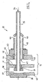
- the FIG. 2 shows the beginning of the removal of the preform 10 from the mold halves. Not shown are the tools for the rejection of semi-rigid preforms of the part forms 8 '.
- the support plate 16 with the blowing mandrels 22 is in the retracted position.
- FIG. 3 a situation for the core function of the new solution.
- the transfer gripper 12 is in the position according to FIG. 2 However, wherein the support plate 16 is shown with the Blasdornen 22 in the extended position.
- blowing mandrels 22 are completely inserted into the cooling sleeves 21, while the preforms are cooled intensively in the cooling sleeves.
- the remainder of the aftercooling takes place only in the aftercooler, after the preforms are dimensionally stabilized by the transfer gripper removed from the sampling device and introduced into the aftercooler.
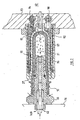
- the FIG. 4 shows the phase of intensive cooling. As an example, only five cooling positions are shown.
- the preforms 10 are cooled both externally and internally. The preforms are held in this phase permanently to the inner bottom part of the cooling sleeves by negative pressure in the space 23 of the removal device 11 or tightened.
- the FIG. 4 shows the use of blown air and suction air via two separate air systems. As an example, only five cooling positions are shown.
- the preforms 10 are cooled both externally and internally.
- the preforms are held in this phase permanently to the inner bottom part of the cooling sleeves by negative pressure in the space 42 of the removal device 11 or tightened.
- the space 23 can be switched as required by valves 24/25 of negative pressure to positive pressure.
- the FIG. 5 shows a blow pin 22 on a larger scale.
- the concept of the cooling pin is based on the assumption that cooling air is extracted at the mouth 34 of a suction pipe 35.
- the suction tube 35 is connected to a vacuum chamber 36 of the support plate 16 via a connection opening 37.
- the suction tube 35 is guided into a sealing screw 38 and sealed by an O-ring 39.
- the support plate 16 is shadowed with a rear wall 40, a middle wall 41 and a front wall 42.
- the vacuum chamber 36 is formed by the rear wall 40 and the middle wall 41.
- the sealing screw 38 is screwed with a thread 44 fixed in the middle wall 41.
- the mandrel 22 is screwed via a cooling pin base 43 and a thread 44 in the front wall 42 and has a jacket 45 with blow holes 46.
- Between coat 45 and the suction pipe 35 is an annular air channel 49 which is connected in the threaded portion via an opening 47 with a pressure chamber 48, so that compressed air via the pressure chamber 48, the opening 47, the annular space 29 and the blowing openings 46 can be blown into the preform interior.
- the pressure chamber 48 is limited by the middle wall 41 and the front wall 42nd
- a blow pin 22 is shown.
- a screw thread 50 by means of which the blowing mandrels 22 are screwed to the support plate 16.
- the support plate 16 has a larger number of nozzles 22, which are each arranged in a plurality of rows.
- two air systems 52 and 53 are arranged, wherein the air system 52 is designed for vacuum and the air system 53 for compressed air with corresponding, not shown, connections for a compressed air generator or a vacuum blower or a vacuum pump.
- the Saugluftitati 61 passes through an annular channel 62 and a plurality of transverse bores 63, which connect the annular channel 62 to the outside close to the sealing ring 60. As a result, air can be blown out via the blowing orifice 64 and drawn in again via the transverse bores 63.
- Flexible and pressure-resistant air hoses 31 and 32 provide the connection to the corresponding compressed air or suction air generators ( FIG. 1 ).
- the air hoses are designed for high pressure and vacuum.
- the entire air system has tube-like connections, which is optimal for the strength issue, both for the high pressure and negative pressure.
- Reference numeral 65 denotes the centering base of the blowing mandrels 22. Die FIG.
- FIG. 6a shows an end portion of the support plate 16 with a screwed-in air nozzle 66.
- the outer diameter DB on the cooling mandrel 22 is slightly smaller than the corresponding inner diameter of the preform 10. This results, supported by the air flow forces, a centering effect for the preform 10 on the tuyeres 22nd ,
- FIG. 6d shows the tuyere in the working position during calibration and the FIG. 6c a preform on average.
- the blow molding 71 has three sections: a neck portion 72, a conical portion 73, and a cylindrical portion 74.
- the neck portion 72 has a substantially smaller wall thickness Ws-2 relative to the cylindrical portion 74 having a wall thickness Ws-1.
- the wall material of the blow-molded part becomes necessary for the enormous enlargement in the blowing process or in the production of PET bottles.
- the tuyere 22 has an annular groove 75 into which a sealing ring 76 is inserted.
- FIG. 6d shows the tuyere 22 in calibration position.
- a gap 79 remains between the shoulder 77 and the edge 78 of the open preform side.
- the sealing ring 76 rests in the conical region 73 on the inner wall of the preform 10 and forms the sealing point 80.
- the sealing point 80 divides the preform inner part into two sections: one front pressure chamber 81 and a rear cooling chamber 82nd
- FIG. 7 shows the situation in the calibration of a preform 10 while external cooling in cooling sleeves according to the embodiment of FIGS. 6a to 6d ,
- the rear refrigerator 82 is indicated with + sign that for the calibration of an overpressure is made.
- the preform insofar as it is located in the cooling sleeve 21, has direct wall contact. This is especially true for the whole bottom part of the preform and the inner bottom part of the cooling sleeve.
- FIG. 8 shows a solution which is particularly in two areas of the solution according to FIG. 7 different.
- the tuyere 22 has a seal 90, 90 ', 90 ", which rises up on the edge 78 and forms the sealing point at the relevant point At the same time, the bottom area 83 is pushed against the arched inner bottom part 91 of the cooling sleeve
- the cooling sleeve 21 has a thin-walled design This is especially true for the dome-like bottom part 91.
- the dome-like bottom part 91 has a neck piece 92, which in one
- the cooling water 30 is introduced via a feed channel 94 into an inner cooling chamber 95, flows along the outer wall surface of the cooling sleeve 21 and leaves it via an opening 96 via an outer cooling chamber 96 and via the return channel 98.
- the air system is designed as a closed system is blown into the interior of the preform 10 via a blow pipe 57 and a Blasmündung 64 of the tuyere. The air is sucked through transverse bores 63 and an annular channel 62 by a vacuum source, not shown. Both sides can be finely tuned by exact control of movements and forces, both mechanical and air forces, especially in the most critical phase of the beginning of calibration with fully inserted preforms.
Description
Die Erfindung betrifft ein Verfahren zur Nachkühlung von Preformen nach der Entnahme aus den offenen Formhälften einer Spritzgiessmaschine, wobei die Preformen in noch heissem Zustand mittels einer Entnahmevorrichtung aus den offenen Formen entnommen und in steuerbaren Phasen mittels wassergekühlten Kühlhülsen nachgekühlt werden, wobei die Preformen in einer Entnahmephase "A" direkt aus den offenen Giessformen entnommen und die Kühlhülsen eingeführt werden und, in einer Phase "B" einer Intensivkühlung unterworfen und anschliessend in einer Nachkühlphase, welche ein Mehrfaches der Spritzzykluszeit beträgt, vollständig gekühlt werden. Die Erfindung betrifft ferner eine Vorrichtung zur Nachkühlung von Preformen nach deren Entnahme aus den offenen Formhälften einer Spritzgiessmaschine, welche Hilfsmittel für das Abstossen der halbstarren Preformen von den Teileformen und eine Nachkühlung der Preformen in einer Entnahmestation sowie einer Nachkühleinrichtung mittels wassergekühlten Kühlhülsen und Blasdorne aufweist, wobei die Entnahmestation eine Entnahmevorrichtung mit horizontal liegend angeordneten Kühlhülsen aufweist, denen in die Preformen einführbare Blasdorne zugeordnet sind, und die Vorrichtung eine Steuerung aufweist zur Steuerung aller Bewegungen für das Handling der Preformen und der Blasdorne sowie für einen Einsatz von Druckluft und gegebenenfalls Saugluft.The invention relates to a method for aftercooling of preforms after removal from the open mold halves of an injection molding machine, wherein the preforms are removed in a still hot state by means of a removal device from the open molds and cooled in controllable phases by means of water-cooled cooling sleeves, wherein the preforms in a removal phase "A" removed directly from the open molds and the cooling sleeves are introduced and, in a phase "B" subjected to intensive cooling and then fully cooled in a Nachkühlphase, which is a multiple of the injection cycle time. The invention further relates to a device for aftercooling of preforms after their removal from the open mold halves of an injection molding machine, which aids for repelling the semi-rigid preforms of the part molds and a Nachkühlung the preforms in a removal station and a Nachkühleinrichtung by means of water-cooled cooling sleeves and Blasdorne, wherein the removal station has a removal device with horizontally arranged cooling sleeves, which are assigned to the preforms insertable mandrels, and the device has a controller for controlling all movements for handling the preforms and the mandrels and for the use of compressed air and optionally suction air.
Bei der Herstellung von Spritzgiessteilen ist für die totale Zeit eines vollen Zyklus die Kühlzeit ein bestimmender Faktor. Die Hauptkühlleistung findet noch in den Giessformhälften statt. Beide Giessformhälften werden während dem Giessprozess intensiv wassergekühlt, so dass die Temperatur der Spritzgiessteile noch in der Form von etwa 280°C, zumindest in den Randschichten, auf einen Bereich von 70° C bis 120° C gesenkt werden kann. Es wird in den äusseren Schichten sehr rasch die sogenannte Glastemperatur von etwa 140° C durchfahren. Der eigentliche Giessvorgang bis zur Entnahme der Spritzgiessteile konnte in der jüngsten Vergangenheit im Falle der Herstellung von dickwandigen Preformen auf etwa 12 bis 15 Sekunden und bei dünnwandigen Preformen auf unter 10 Sekunden gesenkt werden. Dies bei optimalen Qualitäten in Bezug auf die noch halbstarren Preformen. Die Preformen müssen in den Formhälften so stark verfestigt werden, dass diese mit relativ grossen Kräften von den Auswurfhilfen angefasst und ohne Deformation bzw. Schäden einer Entnahmevorrichtung übergeben werden können. Die Entnahmevorrichtung weist eine den Spritzgiessteile-Aussenabmessungen angepasste Form auf. Die intensive Wasserkühlung in den Giessformhälften erfolgt vor allem bei grossen Wandstärken von aussen nach innen, physikalisch bedingt, stark zeitverzögert. Dies bedeutet, dass die genannten 70°C bis 120°C nicht einheitlich im ganzen Querschnitt erreicht werden. Die Folge ist, dass im Materialquerschnitt gesehen eine rasche Rückerwärmung, von innen nach aussen erfolgt; sobald die intensive Wasserkühlung durch die Formen unterbrochen wird. Der Nachkühlung kommt aus zwei Gründen grösste Bedeutung zu. Erstens sollen Formänderungen bis zum formstabilen Lagerzustand aber auch Oberflächenschäden, etwa Druckstellen, usw., vermieden werden. Es muss zweitens verhindert werden, dass die Abkühlung im höheren Temperaturbereich zu langsam erfolgt und sich z.B. durch Rückerwärmungen örtlich schädliche Kristallbildungen einstellen. Ziel ist ein gleichmässig amorpher Zustand im Material der fertigen Preform. Die Resttemperatur soll so tief sein, dass in den relativ grossen Abpackgebinden mit Tausenden von lose eingeschütteten Teilen an den Berührungspunkten keine Haftschäden entstehen können. Die Spritzgiessteile dürfen auch nach leichter Rückenrvärmung eine Oberflächentemperatur von 40°C nicht überschreiten. Die Nachkühlung nach der Entnahme der Preformen aus der Spritzgiessform ist so wichtig wie die Hauptkühlung in den Giessformen.In the production of injection molded parts, the cooling time is a determining factor for the total time of a full cycle. The main cooling performance still takes place in the mold halves. Both mold halves are intensively water-cooled during the casting process, so that the temperature of the injection-molded parts can still be reduced in the form of about 280 ° C, at least in the outer layers to a range of 70 ° C to 120 ° C. It is in the outer layers very quickly pass through the so-called glass transition temperature of about 140 ° C. The actual casting process up to the removal of the injection molding parts has been reduced in the recent past in the case of the production of thick-walled preforms to about 12 to 15 seconds and thin-walled preforms to less than 10 seconds become. This with optimal qualities in relation to the still semi-rigid preforms. The preforms must be so strongly solidified in the mold halves that they can be handled with relatively large forces by the ejection aids and transferred without deformation or damage to a removal device. The removal device has a shape adapted to the dimensions of the injection molded parts. The intensive water cooling in the mold halves takes place especially with large wall thicknesses from the outside to the inside, due to physical reasons, strongly delayed in time. This means that the said 70 ° C to 120 ° C are not uniformly achieved in the entire cross section. The consequence is that seen in the material cross-section, a rapid re-heating, from the inside out; as soon as the intensive water cooling is interrupted by the molds. Aftercooling is of great importance for two reasons. First, shape changes to the dimensionally stable state but also surface damage, such as bruises, etc., should be avoided. Secondly, it must be prevented that the cooling takes place too slowly in the higher temperature range and that, for example, due to rewarming, locally harmful crystal formations occur. The goal is a uniform amorphous state in the material of the finished preform. The residual temperature should be so deep that in the relatively large packaging containers with thousands of loose poured parts at the points of contact no adhesion damage can occur. The injection-molded parts must not exceed a surface temperature of 40 ° C even after slight back heating. Aftercooling after removal of the preforms from the injection mold is as important as the main cooling in the molds.
Die
Bei der
Es wird davon ausgegangen, dass die Bodenkühlung am Wichtigsten ist und es nicht nachteilig ist, wenn durch das Schrumpfen der Preformen in den Kühlhülsen direkt nach der Entnahme aus den Formhälften sich ein geringfügiges Spiel zu den Kühlhülsen bildet. Dies im Gegensatz zu der
Die
Die
Eine ganz besonders interessante Lösung für die Nachkühlung von Preformen nach deren Entnahme aus dem Produktionswerkzeug wird in der
Jede der dargestellten Lösungen hat für sich Vorteile. Dabei werden aber die Vorteile durch spezifische Beschränkungen oder grössere Aufwendungen erkauft. Ein wichtiges Ziel bei der Nachkühlung von Preformen ist neben der Verhinderung von Kristallbildung die grösstmögliche Formerhaltung. Im Rahmen der Nachkühlung besteht die Gefahr, dass sich die Preformen verbiegen und nicht mehr vollkommen achssymmetrisch sind. Die Folge kann sein, dass einzelne Preformen in dem Nachkühler stecken bleiben, so dass bei der nächsten Charge sogenannte Doppelstecker entstehen. Es wird dabei in der selben Kühlhülse eine zweite Preform eingeschoben. Es hat sich gezeigt, dass die ganze Nachkühlung in zwei Abschnitte aufgeteilt werden kann. Eine erste Phase direkt nach der Entnahme der Preformen aus den Formhälften und eine zweite Phase in der relativ lang dauernden Nachkühlung. Die eigentlich heikle Phase ist die erste, welche starken Einfluss auf die Endqualität der Preformen hat. Eine wichtige Erkenntnis der jüngsten Zeit besagt, dass es nicht Ziel ist, die Kristallbildung total zu unterbinden, sondern vielmehr, den kristallinen Anteil im ganzen Preform möglichst tief zu halten.Each of the illustrated solutions has advantages for itself. However, the benefits are paid for by specific restrictions or larger expenses. An important goal in the aftercooling of preforms is, in addition to the prevention of crystal formation, the greatest possible retention of shape. As part of the aftercooling, there is a risk that the preforms bend and are no longer completely axisymmetric. The result may be that individual preforms get stuck in the aftercooler, so that so-called double-plugs arise in the next batch. It is inserted in the same cooling sleeve, a second preform. It has been shown that all aftercooling can be divided into two sections. A first phase immediately after removal of the preforms from the mold halves and a second phase in the relatively long aftercooling. The actually delicate phase is the first to have a strong influence on the final quality of the preforms. One important recent finding is that it is not a goal to totally inhibit crystal formation, but rather to keep the crystalline content as low as possible throughout the preform.
Der neuen Erfindung wurde nun die Aufgabe gestellt, die Kühlung im Hinblick auf eine verkürzte Spritzgiesszykluszeit zu optimieren mit möglichst maximaler Qualität und mit dem kleinstmöglichen Anteil an Kristallbildung der Preformen zu erreichen, ohne grössere verfahrenstechnische Aufwendungen oder Mehrkosten für die Herstellung der Spritzgiessmaschine.The object of the new invention was to optimize the cooling with regard to a shortened injection molding cycle time with as high a quality as possible and with the smallest possible amount of crystallization of the preforms, without major procedural expenses or additional costs for the production of the injection molding machine.
Die Erfindung wird durch ein verfahren gemäß Anspruch 1 und eine Vorrichtung gemäß Anspruch 6 gelößt.The invention is solved by a method according to
Es hat sich gezeigt, dass die erste Nachkühlphase ganz besonders heikel ist, da die Preformen noch ungenügend formstabil sind. Die Gefahr, dass sich der Blasformteil in Bezug auf den Gewindeteil leicht aus der Gewindeachse "verbiegt", ist in der Phase der Entnahme der Preform in liegender Position bei horizontal arbeitenden Spritzgiessmaschinen tatsächlich ein echtes Problem. Dies gilt vor allem, wenn die Kühlzeit innerhalb der Spritzgiessformen auf ein Minimum gebracht und die Preformen noch relativ heiss und entsprechend weich sind. Sind die Preformen in der ersten Phase der Nachkühlung in liegender Lage, dann neigen sie dazu, sich nach unten auf das entsprechende Kühlhülsenteil aufzulegen. Durch einen besseren Kühlkontakt im unteren Bereich wird die Kühlhülse unten stärker abgekühlt, so dass in der Preform Spannungen auftreten und die Preform eine Tendenz zum Verbiegen hat. Wenn in der ersten Phase der Nachkühlung bei verkürzter Kühlung in den Giessformen einzelne Preformen sich leicht deformieren, dann kann die entsprechende Formänderung der zunehmend verfestigten Preformen nicht mehr korrigiert werden.It has been shown that the first aftercooling phase is particularly sensitive, since the preforms are still insufficiently dimensionally stable. The danger that the blow molded part "bends" slightly with respect to the threaded part from the thread axis is actually a real problem in the phase of removing the preform in a lying position in horizontally operating injection molding machines. This is especially true when the cooling time within the injection molds is kept to a minimum and the preforms are still relatively hot and correspondingly soft. If the preforms are in a lying position during the first phase of the aftercooling, then they tend to hang down on the corresponding cooling sleeve part. A better cooling contact in the lower region of the cooling sleeve is cooled down more, so that occur in the preform stresses and the preform has a tendency to bend. If in the first phase of the aftercooling with shortened cooling in the molds individual preforms deform slightly, then the corresponding change in shape of the increasingly solidified preforms can not be corrected.
Die neue Erfindung geht primär von dem Kühlkonzept aus, bei dem die einzelnen Preformen in der Nachkühlung nur mit dem Blasformteil in Kühlhülsen eingeführt werden. Dabei überragen die Gewindeteile die Kühlhülsen. Dies hat den grossen Vorteil, dass die Preformen durch eine Linearbewegung in die Kühlhülsen der Entnahmevorrichtung eingeführt und wieder ausgezogen werden können. Die neue Lösung schlägt besonders in der Phase der Intensivkühlung direkt nach der Entnahme aus den Giessformen einen optimalen Kontakt mit der Kühlhülse vor und erreicht dadurch eine kurze, maximal intensivierte Temperaturabsenkung und Stabilisierung der Preformen in der ersten Nachkühlphase für die anschliessende Fertigkühlung. Die dynamische Einführung der Preformen bis zum vollständigen Wandkontakt in den Kühlhülsen, direkt nach der Entnahme der Preformen aus den Giessformen, jedoch vor dem länger dauernden Fertigkühlen, hat entscheidende Vorteile:The new invention is based primarily on the cooling concept, in which the individual preforms are introduced in the aftercooling only with the blow molded in cooling sleeves. The threaded parts project beyond the cooling sleeves. This has the great advantage that the preforms can be introduced by a linear movement in the cooling sleeves of the removal device and pulled out again. The new solution suggests optimal contact with the cooling sleeve, especially in the phase of intensive cooling immediately after removal from the casting molds, thereby achieving a short, maximum intensified temperature reduction and stabilization of the preforms in the first post-cooling phase for the subsequent final cooling. The dynamic introduction of the preforms to the complete wall contact in the cooling sleeves, directly after the removal of the preforms from the molds, but before the prolonged pre-cooling, has decisive advantages:
Der Kühleffekt ist, physikalisch bedingt, bei der grössten Temperaturdifferenz zwischen heissen Preformen und Kühlhülsen direkt nach der Entnahme aus den Giessformen am grössten. Hierbei ergibt das erzwungene, satte und vollflächige Anliegen der Preformen an die Innenfläche der Kühlhülsen den grösstmöglichen Gewinn durch eine Maximierung der direkten Wärmeleitung. Es findet eine sehr rasche Abkühlung der Preformaussenseite statt. Die Bildung von kristallinen Anteilen wird so auf ein Minimum gesenkt. Die noch heissen Preformen werden direkt nach deren Entnahme aus den Giessformen zur Erhaltung der Formgenauigkeit mit dem geringstmöglichen Spiel in eine Kühlform geschoben. Die nach der Entnahme rasch abgekühlte Preform behält damit beim anschliessenden Handling in Bezug auf die Symmetrie die Formgenauigkeit.The cooling effect is, for physical reasons, at the greatest temperature difference between hot preforms and cooling sleeves directly after removal from the molds largest. In this case, the forced, rich and full-surface concerns of the preforms to the inner surface of the cooling sleeves results in the greatest possible profit by maximizing the direct heat conduction. There is a very rapid cooling of Preformaussen instead. The formation of crystalline fractions is thus reduced to a minimum. They are still hot Preforms are pushed into a cooling mold with the least possible play immediately after their removal from the molds to maintain the dimensional accuracy. The rapidly cooled preform after removal thus retains its shape accuracy during subsequent handling with respect to symmetry.
Bereits erste Tastversuche zeigten, dass die neue Lösung bei vollständiger Erhaltung der Qualitätsparameter eine Verkürzung der Giesszykluszeit von einer halben Sekunde erlaubte, was einer Steigerung der Produktivität von etwa 5% entspricht. Dies, weil die Preformen mit noch höherer Temperatur, somit schneller als im Stand der Technik, aus den Formen entnommen werden können. In der allerersten Phase der Nachkühlung ist das Anliegen des noch weichen Blasformteiles an die Innenwand der Kühlhülsen mit minimalen Luftdruckkräften möglich. Die Bewegung der Blasdorne erfolgt zeitlich im Rhythmus des Spritzgiesszyklus getaktet und die Einführbewegung weg- und/oder kraftgesteuert.Already first tactile tests showed that the new solution allowed a reduction of the casting cycle time of half a second with complete preservation of the quality parameters, which corresponds to an increase of the productivity of about 5%. This is because the preforms with even higher temperature, thus faster than in the prior art, can be removed from the molds. In the very first phase of the aftercooling of the still-soft blow molding is possible to the inner wall of the cooling sleeves with minimal air pressure forces. The movement of the blowing mandrels is timed in the rhythm of the injection molding cycle and the insertion movement away and / or force controlled.
Die Kühlhülse wird im inneren Durchmesser höchstens um einige Hundertstel Millimeter grösser gewählt als die Aussenabmessungen der noch heissen Preformen. Durch eine gezielte Steuerung von Saug- und Blasluft kann ein Blähdruck erzeugt und die Preform zum vollständigen Anliegen an die ganze Innenwandfläche der Kühlhülse gebracht werden. Nach dem erstmaligen Anliegen der Preformen an die Innenwandfläche der Kühlhülsen wird der Flächenkontakt über mehrere Sekunden aufrechterhalten und dadurch die Kühlwirkung maximiert. Gleichzeitig wird ein Kalibrationseffekt für jede einzelne Preform erzeugt. Der Kalibrationseffekt gibt bei der Herstellung von Preformen die Möglichkeit für einen Produktions- und Qualitätsstandard, wie er im Rahmen des Standes der Technik nicht möglich war. Die Preformen werden kurz nach der Entnahme aus den Giessformen nochmals in eine exakte Form gepresst, so dass allfällige Massveränderungen nach dem ersten kritischen Handling aus den Giessformen in die Kühlhülsen, insbesondere ein Biegen der Preformen durch einseitiges Aufliegen in der Kühlhülse, ausgeschaltet werden können. Der Kalibrationseffekt gestattet, die Preformen noch früher den Formen zu entnehmen und dadurch eine noch kürzere Giesszykluszeit, ferner eine verbesserte erste Phase der Nachkühlung zu erreichen. Dies ist besonders im Hinblick auf das raschest mögliche Durchfahren der Glastemperatur und damit der schädlichen Kristallbildung sehr vorteilhaft. Die anschliessende Nachkühlung kann problemfreier in Bezug auf alle qualitativen Parameter in der erforderlichen Zeit durchgeführt, Preformen mit höchster Qualität erzeugt und gleichzeitig die Produktivität der Spritzgiessmaschine gesteigert werden. Die Erfindung erlaubt eine ganze Anzahl vorteilhafter Ausgestaltungen. Es wird dazu auf die Ansprüche 2 bis 5 sowie 7 bis 15 Bezug genommen.The cooling sleeve is selected in the inner diameter at most by a few hundredths of a millimeter larger than the outer dimensions of the still hot preforms. Through targeted control of suction and blowing air, a swelling pressure can be generated and the preform be brought to complete concern to the entire inner wall surface of the cooling sleeve. After the preforms have been applied to the inner wall surface of the cooling sleeves for the first time, the surface contact is maintained for several seconds, thereby maximizing the cooling effect. At the same time, a calibration effect is generated for each individual preform. The calibration effect gives the possibility of a production and quality standard in the production of preforms, as it was not possible in the context of the prior art. The preforms are pressed shortly after removal from the molds again in an exact shape, so that any dimensional changes after the first critical handling of the molds in the cooling sleeves, in particular a bending of the preforms can be turned off by one-sided resting in the cooling sleeve. The calibration effect allows the preforms to be removed even earlier from the molds, thereby achieving an even shorter casting cycle time, as well as an improved first phase of aftercooling. This is very advantageous especially with regard to the fastest possible passage through the glass transition temperature and thus the harmful crystal formation. The subsequent after-cooling can be carried out more problem-free with respect to all qualitative parameters in the required time, produces preforms of the highest quality and at the same time increases the productivity of the injection molding machine. The invention allows a number of advantageous embodiments. Reference is made to the
Im Stand der Technik ist eine Lösung bekannt, bei der die Preform aussen konisch ausgebildet wird, wobei die Preform anfänglich nur teilweise eingeschoben, mit entsprechendem Unterdruck auf der Gegenseite schrittweise eingezogen und dauernd über die ganze Nachkühlzeit ein guter Wandkontakt mit der Kühlhülse aufrechterhalten wird. Der grosse Nachteil liegt darin, dass die Bodenpartien der Preformen nur sehr schlecht von aussen gekühlt werden. Bei der neuen Lösung wird das vollständige Einschieben dynamisch möglichst ohne Zeitverzug, im Wesentlichen innert Sekunden, durchgeführt. Der Wandkontakt kann mit dem leichten Blähdruck während dem Rest der Intensivkühlung aufrechterhalten werden. Für die Erzeugung des Blähdruckes weist jeder Blasdorn Blasluftöffnungen auf und wird gegenüber der jeweiligen Preform leicht abdichtend aufgesetzt. Blasluft und Saugluft werden dabei derart gesteuert, dass während der intensiven Kühlung ein leichter Überdruck in jeder Preform erzeugt, die Preform an die Innenwandung der Kühlhülse angepresst und dadurch kalibriert wird.In the prior art, a solution is known in which the preform is formed externally conical, the preform initially inserted only partially, with corresponding negative pressure on the opposite side gradually retracted and maintained a good wall contact with the cooling sleeve over the entire post-cooling time. The big disadvantage is that the bottom parts of the preforms are cooled very badly from the outside. With the new solution, the complete insertion is performed dynamically as far as possible without delay, essentially within seconds. The wall contact can be maintained with the slight inflation pressure during the remainder of the intensive cooling. For the generation of the inflation pressure, each mandrel has blown air openings and is placed slightly sealingly relative to the respective preform. Blowing air and suction air are controlled in such a way that generates a slight overpressure in each preform during intensive cooling, the preform is pressed against the inner wall of the cooling sleeve and thereby calibrated.
Ein wichtiges Ziel der neuen Lösung liegt darin, dass der Kühleinsatz während der intensiven Kühlung gestuft erfolgt. Die noch vorhandenen Temperaturunterschiede in den Preform werden nach der Entnahme aus den Giessformen so rasch wie möglich beseitigt. Gleichzeitig gelingt es, kristalline Anteile in der ganzen Preform auf den tiefstmöglichen Wert zu senken, wobei die Preform für die anschliessende Nachkühlung in einen vollständig formstabilen Zustand gebracht wird. Wenn die Preform bereits am Beginn der Nachkühlung die bestmögliche Symmetrie in Bezug auf die ganze äussere Form hat, kann nahezu mit Sicherheit die Gefahr von sogenannten Doppelsteckern auf Grund von verbogenen Preformen und entsprechenden Betriebsstörungen ausgeschlossen werden.An important goal of the new solution is that the cooling insert is stepped during intensive cooling. The remaining temperature differences in the preform are removed as soon as possible after removal from the molds. At the same time, it is possible to reduce crystalline proportions in the entire preform to the lowest possible value, with the preform being brought into a completely dimensionally stable state for the subsequent after-cooling. If the preform has the best possible symmetry with respect to the outer shape already at the beginning of aftercooling, the danger of so-called double plugs due to bent preforms and corresponding malfunctions can almost certainly be ruled out.
Die intensive Kühlung beträgt nur ein Bruchteil der ganzen Nachkühlung. Während der intensiven Kühlung wird die Temperatur im Mittel um 20 °C bis 40 °C abgesenkt. Eine starke Verlängerung der intensiven Kühlphase ist nicht vorteilhaft, weil die Wärmewanderung innerhalb dem Preformmaterial nicht gesteigert werden kann.The intensive cooling is only a fraction of the total aftercooling. During the intensive cooling, the temperature is lowered on average by 20 ° C to 40 ° C. A strong prolongation of the intensive cooling phase is not advantageous because the heat migration within the preform material can not be increased.
Die Blasdorne weisen einen als Sockel ausgebildeten Mantel auf, welcher einerseits Ausblasöffnungen für Kühlluft hat und andererseits über die Trägerplatte mit einer Druckluftquelle verbindbar ist, wobei der Mantel vorzugsweise über weniger als die halbe Länge des Saugrohres geführt ist. Die Trägerplatte wird mit zwei Kammern ausgebildet, eine erste Kammer mit Anschluss an eine Vakuumquelle und eine zweite Kammer mit Anschluss an eine Druckluftquelle, wobei das Saugrohr durch die zweite Kammer hindurch geführt und die erste Kammer direkt mit dem Raum zwischen dem Mantel und dem Saugrohr verbunden ist. Sowohl für die Saugluft wie für die Blasluft werden steuerbare Ventile angeordnet, so dass der zeitliche Einsatz optimierbar ist.The blowing mandrels have a base formed as a shell, which has on the one hand Ausblasöffnungen for cooling air and on the other hand via the support plate with a compressed air source is connected, wherein the jacket is preferably guided over less than half the length of the suction tube. The carrier plate is formed with two chambers, a first chamber connected to a vacuum source and a second chamber connected to a compressed air source, wherein the suction pipe passed through the second chamber and the first chamber directly connected to the space between the jacket and the suction tube is. For the suction air as well as for the blown air controllable valves are arranged, so that the temporal use can be optimized.
Die neue Lösung weist eine Entnahmevorrichtung mit Kühlhülsen und eine dazu bis zu einem Dichtschluss bewegbare Trägerplatte des Transfergreifers mit einem Kühlluftanschluss auf. Die Trägerplatte ist entsprechend der Zahl der Kühlhülsen mit Blasdorne mit Dichtungsringen bestückt, welche zu je einer Preform im Preforminneren eine Dichtstelle bilden zur Erzeugung eines leichten Blähdruckes im Inneren der Preformen. Die Dichtstelle ist in Bezug auf das offene Ende der Preformen angeordnet und wirkt erst am Ende der Einführbewegung der Blasdorne. Bevorzugt wird die Dichtstelle zwischen den einzelnen Blasdorne und dem äusseren Rand des Gewindeteiles der Preformen durch eine Weichdichtung hergestellt und der Rand des Gewindeteiles über die elastische Dichtung gehalten.The new solution has a removal device with cooling sleeves and a movable to a sealing closure support plate of the transfer gripper with a Cooling air connection on. The support plate is equipped with bladders according to the number of cooling sleeves with sealing rings, which form a sealing point for each preform in Preforminneren to generate a slight inflation pressure in the interior of the preforms. The sealing point is arranged with respect to the open end of the preforms and acts only at the end of the insertion movement of the blowing mandrels. Preferably, the sealing point between the individual blowing mandrels and the outer edge of the threaded portion of the preforms is made by a soft seal and the edge of the threaded portion held over the elastic seal.
Eine dritte Ausgestaltung ist dadurch gekennzeichnet, dass die Vorrichtung für eine Innenkühlung in die Preformen einführbare Blasdorne einer gesteuert verschiebbaren Trägerplatte aufweist, wobei die einzelnen Blasdorne in Bezug auf die Preformen in Richtung der Einführbewegung nachgebend ausgebildet sind, derart, dass jeder Blasdorn mit kontrollierter Kraft bis zum Kontakt der inneren Dompartie der Preformen einführbar ist. Die Blasdorne können einen verschiebbar angeordneten Kontaktkopf und eine bis zum Kontaktkopf durchgehend geführte Luftbohrung aufweisen, welche in eine zwischen Blasdorn und Kontaktkopf in der Grösse veränderbare Blasluftkammer mündet. Vorteilhafterweise weist jeder Blasdorn für die Erzeugung einer kontrollierten Andrückkraft eine Druckfeder auf. Die Blasdorne werden mit einem Kontaktkühlkopf ausgebildet, zur mechanischen Kontaktierung und Kontaktkühlung der entsprechenden inneren Dompartie des jeweiligen Preforms, wobei die kontrollierte Kraft durch Blasluft und/oder durch eine Druckfeder erzeugbar ist. Der Kontaktkopf wird bevorzugt hülsenartig auf dem Blasdorn zwischen einer maximal ausgeschobenen und angezogenen Lage frei verschiebbar angeordnet.A third embodiment is characterized in that the device for internal cooling in the preforms insertable mandrels of a controllably displaceable support plate, wherein the individual mandrels are formed with respect to the preforms in the direction of insertion movement, such that each mandrel with controlled force until to the contact of the inner Dompartie the preforms is insertable. The blowing mandrels may have a contact head arranged displaceably and an air bore guided continuously up to the contact head, which opens into a blowing air chamber which can be changed in size between the mandrel and the contact head. Advantageously, each mandrel for generating a controlled pressing force on a compression spring. The blowing mandrels are formed with a contact cooling head, for mechanical contacting and contact cooling of the corresponding inner Dompartie of the respective preform, wherein the controlled force can be generated by blowing air and / or by a compression spring. The contact head is preferably arranged sleeve-like manner on the mandrel between a maximally pushed-out and tightened position freely displaceable.
Als einfachste und preisgünstigste konstruktive Gestaltung weist jeder Blasdorn einen verschiebbar angeordneten Kontaktkopf auf. Dabei wird bei jedem der Blasdorne eine bis zum Kontaktkopf durchgehend geführte Blasluftbohrung vorgesehen, welche in eine in der Grösse veränderbare Blasluftkammer mündet. Jeder Kontaktkopf ist hülsenartig auf dem Blasdorn zwischen einer maximal ausgeschobenen und angezogenen Lage frei verschiebbar angeordnet, wobei die ausgeschobene Lage durch die Blasluft und/oder eine Druckfeder und die angezogene Lage durch Unterdruck herstellbar ist. Die Kontaktköpfe können in dem Bereich der Kontaktspitze wenigstens eine Blasluftöffnung aufweisen, welche mit der Blasluftkammer verbunden sind. Die Kontaktspitze kann in dem Angussbereich der Preform geschlossen ausgebildet werden zur rein mechanischen Kontaktierung des entsprechenden innersten Teiles der Dompartie des jeweiligen Preforms. Jeder Blasdorn weist vorteilhafterweise einen an der Trägerplatte fixierbaren Blasdornsockel mit einer rohrförmigen Verlängerung in Blasluftrichtung auf, wobei der Kontaktkopf gegenüber der rohrförmigen Verlängerung verschiebbar ist. Der Kontaktkopf und der Blasdornsockel werden zumindest angenähert zylindrisch ausgestaltet, derart, dass zwischen den zylindrischen Formen und der Preforminnenseite sich eine Engstelle mit erhöhter Geschwindigkeit für die abströmende Blasluft bildet. In dem Bereich des Blasdornsockels können Querbohrungen angeordnet werden, welche an einer Vakuumquelle anschliessbar sind, um eine sichere Entnahme der Preformen aus den Kühlhülsen und eine Übergabe an den eigentlichen Nachkühler zu gewährleisten.As the simplest and cheapest structural design, each mandrel has a slidably disposed contact head. In this case, in each of the blowing mandrels, a blowing air bore which is guided continuously up to the contact head is provided which opens into a blow-air chamber which can be changed in size. Each contact head is sleeve-like arranged freely displaceable on the mandrel between a maximally pushed-out and tightened position, wherein the ejected position can be produced by the blowing air and / or a compression spring and the tightened position by negative pressure. The contact heads may have in the region of the contact tip at least one blown air opening, which are connected to the blown air chamber. The contact tip can be formed closed in the sprue area of the preform for purely mechanical contacting of the corresponding innermost part of the Dompartie of the respective preform. Each mandrel advantageously has a fixable on the support plate Blasdornsockel with a tubular extension in Blasluftrichtung on, wherein the contact head relative to the tubular extension is displaceable. The contact head and the mandrel base are at least approximately cylindrical in shape, such that between the cylindrical forms and the Preforminnenseite forms a bottleneck with increased speed for the outflowing blast air. In the area of the Blasdornsockels transverse bores can be arranged, which can be connected to a vacuum source to ensure safe removal of the preforms from the cooling sleeves and a transfer to the actual aftercooler.
Die neue Lösung weist eine Nachkühlstation sowie eine Intensivkühlstation auf, wobei in der Intensivkühlstation sowohl die Preforminnenseite wie die Preformaussenseite innerhalb der Zeit eines Spritzgiesszyklusses intensiv kühlbar ist. Die Intensivkühistation kann als baulich unabhängig steuerbare Entnahmestation oder als Teil eines Nachkühlers ausgebildet sein, welcher eine Menge an Kühlhülsen aufweist, entsprechend mehrerer Chargen eines Spritzgiesszyklusses, besonders vorzugsweise von vier Chargen. Die ganze Nachkühlung weist eine Steuerung auf zur Steuerung aller Bewegungen für das Handling der Preformen und der Blasdorne sowie für einen zyklisch getakteten Einsatz von Druckluft und Saugluft, ferner einen Entnahmeroboter mit Kühlhülsen, einen Transfergreifer mit der Trägerplatte mit steuerbaren Bewegungen in Bezug auf die Blasdorne, wobei die Preformen durch den Transfergreifer nach einer Intensivkühlung in den Kühlhülsen des Entnahmeroboters an den Nachkühler zur vollständigen Abkühlung übergebbar sind.The new solution has a Nachkühlstation and an intensive cooling station, wherein in the intensive cooling station both the Preforminnenseite as the Preformaussenseite within the time of Spritzgiesszyklusses is intensively coolable. The intensive cooling station can be designed as a structurally independently controllable removal station or as part of an aftercooler, which has a quantity of cooling sleeves, corresponding to several batches of an injection molding cycle, particularly preferably four batches. The entire aftercooling has a control to control all movements for the handling of the preforms and the mandrels and for a cyclically timed use of compressed air and suction air, also a removal robot with cooling sleeves, a transfer gripper with the support plate with controllable movements with respect to the mandrels, wherein the preforms are transferable by the transfer gripper after intensive cooling in the cooling sleeves of the removal robot to the aftercooler for complete cooling.
Eine weitere vorteilhafte Ausgestaltung ist dadurch gekennzeichnet, dass die aussen wassergekühlten Kühlhülsen eine innere Form aufweisen, welche mit Einschluss des gewölbten Bodenteiles der äusseren Form der Preform entspricht und die Kühlhülse mit Einschluss des gewölbten Bodenteiles möglichst dünnwandig ausgebildet ist, so dass über die ganze Kühlhülse und von der Kühlhülse auf die Preformaussenseite durch das kurzzeitige Anliegen ein maximaler Wärmedurchgang bzw. Wärmeübergang hergestellt wird.A further advantageous embodiment is characterized in that the outer water-cooled cooling sleeves have an inner shape which corresponds to the inclusion of the curved bottom part of the outer mold of the preform and the cooling sleeve is formed with the inclusion of the curved bottom part as thin as possible, so that over the entire cooling sleeve and from the cooling sleeve on the Preformaussenseite by the short-term concerns a maximum heat transfer or heat transfer is made.
Je nach Wandstärke dauert der Giesszyklus 10 bis 15 Sekunden und der totale Zyklus mit Einschluss der ganzen Nachkühlung 30 bis 60 Sekunden. Die Leistungsfähigkeit der Maschine wird jedoch durch die Giesszykluszeit bestimmt. Die Kalibrierung findet während der ersten Phase der Nachkühlung statt, wobei in einer ersten Phase Druckluft von 1 bis 10 bar eingeblasen wird.Depending on the wall thickness, the casting cycle lasts 10 to 15 seconds and the total cycle including the entire after-cooling takes 30 to 60 seconds. However, the performance of the machine is determined by the casting cycle time. The calibration takes place during the first phase of the after-cooling, whereby in a first phase compressed air of 1 to 10 bar is injected.
Bevorzugt wird die Kühlung der Preformen von der Entnahme aus den Formhälften bis zur Fertigkühlung nicht unterbrochen. Die Blasdorne weisen einen Dichtring aus Weichgummi auf. Auf diese Weise wird sichergestellt, dass auf das Gewindeteil keine Deformationskräfte wirken. Vorteilhafterweise wird auch während dem Einfahren der Blasdorne eine örtliche Kühlung und eine Verfestigung der Oberfläche erzeugt, welche in einer ersten Phase auf das offene Gewindeende sowie das Bodenteil der Preform gerichtet ist.Preferably, the cooling of the preforms from the removal from the mold halves is not interrupted until the final cooling. The blowing mandrels have a sealing ring made of soft rubber. In this way it is ensured that act on the threaded portion no deformation forces. Advantageously, a local cooling and solidification of the surface is also generated during retraction of the blowing mandrels, which is directed in a first phase to the open threaded end and the bottom part of the preform.
Die neue Lösung teilt die Nachkühlung in zwei unabhängig steuerbare Phasen:
- eine erste Intensivkühlung beschränkt sich auf den Zeitraum eines Spritzzyklus. Die Intensivkühlung findet statt, während der nächste Spritzzyklus abläuft, während einer Zeitspanne von z.B. 5
bis 15 Sekunden. - Die eigentliche Nachkühlung benötigt ein Mehrfaches an Zeit, meistens das 3- bis 4-fache der Spritzgiesszeit. Hier macht eine Intensivkühlung wirtschaftlich wenig Sinn, weil die Wärmewanderung innerhalb der Wandstärken der Preformen wenig beeinflussbar ist.
- a first intensive cooling is limited to the duration of one injection cycle. The intensive cooling takes place while the next injection cycle is in progress for a period of
eg 5 to 15 seconds. - The actual after-cooling requires a multiple of time, usually 3 to 4 times the injection molding time. In this case, intensive cooling makes little economic sense, because the heat migration within the wall thicknesses of the preforms is hardly influenceable.
In der Folge wird die neue Erfindung an Hand einer Anzahl Ausführungsbeispiele mit weiteren Einzelheiten erläutert. Es zeigen:
- die
Figur 1 - schematisch eine Gesamtansicht einer Spritzgiessmaschine für die Herstellung von Preformen mit einer Entnahmevorrichtung sowie einem Transfergreifer, ausgerüstet mit einer Vielzahl von Blasdornen;
- die
Figuren 2 - und 3 je einen Schritt nach Beendigung des Spritzzyklus; bei der
Figur 2 übernimmt die Entnahmevorrichtung die noch heissen Preformen aus den offenen Formhälften. DieFigur 3 zeigt den Moment der Intensivkühlung der Preformen; - die Figur 4
- ausschnittsweise eine Übersicht der Phase der Intensivkühlung in der Entnahmevorrichtung;
- die
Figuren 5 - zeigt ein Trägerplattenstück mit einer Blasdüse;
- die Figuren 6a
- bis 6d zeigen einen Kühlstift als Blasdüse ausgebildet in verschiedenen Situationen, die
Figur 6a ein Trägerplattenstück mit einer Blasdüse, dieFigur 6b eine einzelne Blasdüse, dieFigur 6c eine Preform und dieFigur 6d die Blasdüse in Kalibrierposition; - die Figur 7
- ein Beispiel für eine Situation in der Phase einer eigentlichen Kalibration einer einzelnen Preform;
- die
Figur 8 - eine optimierte Lösung in Bezug auf die Kalibration einer Preform sowie die Ausgestaltung einer wassergekühlten Kühlhülse hinsichtlich Wärmeübergang bzw. Wärmedurchgang.
- the figure 1
- schematically an overall view of an injection molding machine for the production of preforms with a removal device and a transfer gripper equipped with a plurality of Blasdornen;
- Figures 2
- and 3 each one step after completion of the injection cycle; in the
FIG. 2 the removal device takes over the still hot preforms from the open mold halves. TheFIG. 3 shows the moment of intensive cooling of the preforms; - FIG. 4
- a detailed overview of the phase of intensive cooling in the sampling device;
- Figures 5
- shows a carrier plate piece with a blowing nozzle;
- Figures 6a
- to 6d show a cooling pin as a blowing nozzle formed in different situations, the
FIG. 6a a carrier plate piece with a tuyere, theFIG. 6b a single tuyere thatFIG. 6c a preform and theFIG. 6d the tuyere in calibration position; - the figure 7
- an example of a situation in the phase of actual calibration of a single preform;
- the figure 8
- an optimized solution in relation to the calibration of a preform and the design of a water-cooled cooling sleeve with respect to heat transfer or heat transfer.
Die
- "A" ist die Entnahme der Spritzgiessteile oder Preformen 10 aus den beiden Formhälften. Die noch halbstarren hülsenförmigen Teile werden dabei mittels Kühlhülsen 21 von einer in den Raum zwischen den geöffneten Formhälften und in die Position "A"
abgesenkten Entnahmevorrichtung 11 aufgenommen und mit dieser in die Übergabeposition "B" angehoben. - "B" ist die Phase der Intensivkühlung,
wobei Blasdorne 22 auf einer gesteuert bewegbaren Trägerplatte gehalten und indie Preformen 10 eingeführt werden (Figur 2b). - "C" ist die
Übergabe der Preformen 10von einem Transfergreifer 12 aneine Nachkühleinrichtung 19. - "D" ist der Abwurf der abgekühlten und in einen vollständig formstabilen Zustand gebrachten Preforms aus der
Nachkühleinrichtung 19.
- "A" is the removal of the injection molded parts or preforms 10 from the two mold halves. The still semi-rigid sleeve-shaped parts are thereby taken by means of cooling
sleeves 21 of a lowered into the space between the open mold halves and in the position "A"removal device 11 and raised with this in the transfer position "B". - "B" is the phase of intensive cooling, wherein
tuyeres 22 are held on a controlled movable support plate and inserted into the preforms 10 (Figure 2b). - "C" is the transfer of the
preforms 10 from atransfer gripper 12 to a post-cooler 19. - "D" is the discharge of the cooled and placed in a completely dimensionally stable state preforms from the Nachkühleinrichtung 19th
Die
Die grösste Temperaturabsenkung der Spritzgiessteile 10 von etwa 280° C auf 120° C geschieht noch innerhalb der geschlossenen Formen 8 und 9, wozu ein enormer Kühlwasserdurchsatz sichergestellt werden muss. Die Entnahmevorrichtung 11 ist in strichlierter Darstellung in einer Warteposition, womit das Ende der Spritzphase angedeutet ist. Das Bezugszeichen 30 ist die Wasserkühlung mit entsprechenden Zu- bzw. Abführleitungen, welche zur Vereinfachung mit Pfeilen dargestellt sind und als bekannt vorausgesetzt werden. Das Bezugszeichen 31/32 bezeichnet die Luftseite, wobei 31 für Einblasen resp. Druckluftzufuhr und 32 für Vakuum resp. Luftabsaugen steht. In den Spritzgiessformen 8 und 9 werden die Preformen noch während dem Spritzzyklus gleichzeitig innen und aussen gekühlt. In den Kühlhülsen der Entnahmevorrichtung 11 findet zuerst nur eine Aussenkühlung statt. Ein weiterer interessanter Punkt ist das Handling in dem Bereich der Nachkühlvorrichtung 19. Die Nachkühlvorrichtung kann während der Entnahmephase "A" gemäss Pfeil L horizontal unabhängig verfahren werden von einer Aufnahmeposition in eine Abwurfposition (strichliert dargestellt). Die Nachkühlvorrichtung 19 weist ein Mehrfaches an Fassungsvermögen gegenüber der Kavitätenzahl in den Spritzgiessformhälften auf. Der Abwurf der fertig gekühlten Preforms 10 erfolgt dadurch erst nach zwei, drei oder mehr Spritzgiesszyklen, so dass entsprechend die Nachkühlzeit gegenüber dem Giesszyklus verlängert wird. Für die Übergabe der Preformen von dem Transfergreifer 12 an die Nachkühleinrichtung 19 kann letztere zusätzlich querverschoben und in die passende Position gesetzt werden.The largest temperature reduction of the injection molded
In den
Die
Die
In den
Die
Die
Die
Claims (15)
- A method for the secondary cooling of preforms (10) after removal from the open mould halves (8, 9) of an injection moulding machine, wherein the preforms (10) are removed with water-cooled cooling sleeves (21) from the open moulds (8, 9) while still hot by means of a removal device (11) and undergo secondary cooling in controllable phases, wherein the removal device (11) is movable between the open moulds (8, 9), wherein the preforms in a removal phase "A" are removed directly from the open casting moulds (8, 9) and are dynamically introduced into the cooling sleeves (21) and in a phase "B" are subjected to an intensive cooling which includes the inside as well as the outside of a blow mould part of the preforms (10), and are subsequently completely cooled in a secondary cooling phase which is a multiple of the injection cycle time,
characterized in that
the preforms (10) shortly after the removal phase "A" in the cooling sleeves (21), the internal diameters of which are selected to be greater than the external dimensions of the still hot preforms, are applied completely against the entire inner wall surface of the water-cooled cooling sleeves (21) of the removal device (11) by means of a swelling pressure, which is generated by a targeted controlling of compressed air and suction air, and are brought again into an exact form, and that during phase "B" a calibration of the preforms (10) by means of the swelling pressure and an intensive cooling take place. - The method according to Claim 1,
characterized in that
the movement of blow pins (22) is synchronized chronologically with the rhythm of the injection moulding cycle and the introduction movement takes place in a controlled manner with respect to displacement and/or power. - The method according to Claim 1 or 2,
characterized in that
each blow pin (22) is placed in a sealing manner relative to the respective preform (10) and blast air or suction air are controlled so that an overpressure is generated in each preform (10) during the intensive cooling and the preform (10) is pressed against the inner wall of the cooling sleeve (21) and thereby calibrated. - The method according to Claim 1,
characterized in that
the blow pin (22) is surrounded by an inflatable casing (150), wherein a cooling- or respectively pressure fluid circulates in the interior of the casing (150) to calibrate and cool the preform (10). - The method according to one of Claims 1 to 4,
characterized in that
the dynamic introduction in the removal device (11) takes place through the controlled generation of negative pressure on sides of the cooling sleeves (21) or respectively on the outer perform base (84) and the removal from the removal device (11) takes place by switching to overpressure on the outer preform base (84). - An injection moulding system with partial moulds (8', 9') and a device in particular to carry out a method according to Claim 1, for the secondary cooling of preforms (10) after they have been removed from the open mould halves (8, 9) of an injection moulding machine, which device comprises auxiliary means for ejecting the semi-rigid preforms (10) from the partial moulds (8', 9') and a secondary cooling of the preforms (10) in a removal station as well as in a secondary cooling means (19) having a multiple of volumetric capacity with respect to the cavity number in an injection moulding half, wherein the removal station has a removal device (11) with water-cooled cooling sleeves (21) arranged lying horizontally, to which blow pins (22) to be introduced into the preforms (10) are assigned, wherein the removal device (11) is movable between the open moulds, and the device has a control to control all movements for the handling of the preforms (10) and the blow pins (22) as well as for a use of compressed air and suction air, if applicable,
characterized in that
the inner form of the horizontally lying cooling sleeves (21) of the removal device (11) are adapted to the corresponding inner form of the partial mould (9') in such a way that the internal diameter of the cooling sleeves (21) is selected to be greater than the external dimensions of the preforms (10) which are still hot, and that the preforms (10) directly after removal from the casting moulds (8, 9) can be introduced dynamically by a linear movement until they lie with the entire surface against the water-cooled cooling sleeves (21) for a quick cooling of the outside of the preform, and can again be brought into an exact form, wherein the removal device (11) is constructed as an intensive cooling station in which the preforms (10) are able to be subjected to a calibration- and intensive cooling phase wherein by means of the blow pins (22) by targeted controlling of compressed air and suction air a swelling pressure can be generated so that the preforms (10) can be applied by means of the swelling pressure completely against the entire inner wall surface of the water-cooled cooling sleeves (21), and wherein the intensive cooling phase includes the inner and the outer side of a blow mould part of the preforms (10). - The injection moulding system according to Claim 6,
characterized in that
each blow pin (22) has a casing constructed as a base (100), which can be connected with a compressed air source via the supporting plate (16). - The injection moulding system according to Claim 7,
characterized in that
it has a removal device (11) with cooling sleeves (21) and a supporting plate (16) of the transfer gripper (12, 12'), which can be moved up to a tight closure with a compressed air connection to generate a brief swelling pressure inside the preforms (10) such that each preform (10), directly after removal from the mould halves (8, 8'), can be calibrated in the cooling sleeves (21) of the removal device (11) while it is still hot. - The injection moulding system according to Claim 8,
characterized in that
the supporting plate (16) has blow pins with elastic seals (76) corresponding to the number of cooling sleeves (21), which form a sealing site (80) to each respective preform (10) in the inside of the preform to generate the swelling pressure in the interior of the performs (10). - The injection moulding system according to Claim 8,
characterized in that
the sealing site is arranged relative to the open end of the preforms (10) and can be established at the end of the introduction movement of the blow pins (22) to generate a sufficient swelling pressure inside the preforms (10) or respectively over the inner area of the cooling sleeve (21), wherein the sealing side between the individual blow pins (22) and the outer edge of the threaded part of the preforms (10) is able to be established by a soft seal (90, 90', 90"). - The injection moulding system according to Claim 6,
characterized in that
the blow pins (22) are constructed as blow pins and have a movably arranged contact head (103) and a blast air bore (111) guided continually up to the contact head (103), which runs into a blast air chamber (112) between the blow pin (22) and the contact head (103/106) and is variable in size. - The injection moulding system according to Claim 11,
characterized in that
the blow pins (22) are constructed with a contact cooling head for the mechanical contacting and contact cooling (106) of the corresponding inner pin part (99) of the respective preform, wherein the controlled power is able to be generated by blast air and/or by a compression spring (134). - The injection moulding system according to Claim 11,
characterized in that
the contact head (103) is arranged in the manner of a sleeve on the blow pin (22) between a maximally extended and tightened position so as to move freely, wherein the moving force is effected by the blast air and/or by a compression spring (134). - The injection moulding system according to Claims 6 to 13,
characterized in that
the intensive cooling station is constructed as a structurally independently controllable removal station or as part of a secondary cooler (19) which has a number of cooling sleeves (21) corresponding to several batches of an injection moulding cycle. - The injection moulding system according to one of Claims 6 to 14,
characterized in that
it has a removal robot with cooling sleeves (21), a transfer gripper (12) with the supporting plate (16) with controllable movements relative to the blow pins (22), wherein the preforms (10) are able to be transferred by the transfer gripper (12) to the secondary cooling means (19) for complete cooling after an intensive cooling in the cooling sleeves (21) of the removal robot, wherein the device has a control means to control all movements for the handling of the preforms (10) and the blow pins (22) as well as for a cyclically clocked use of compressed air and, if applicable, suction air.
Applications Claiming Priority (7)
| Application Number | Priority Date | Filing Date | Title |
|---|---|---|---|
| CH185002 | 2002-11-05 | ||
| CH18502002 | 2002-11-05 | ||
| CH632003 | 2003-01-17 | ||
| CH63032003 | 2003-01-17 | ||
| CH247032003 | 2003-02-19 | ||
| CH2472003 | 2003-02-19 | ||
| PCT/CH2003/000132 WO2004041510A1 (en) | 2002-11-05 | 2003-02-21 | Method and device for the secondary treatment and the cooling of preforms |
Publications (3)
| Publication Number | Publication Date |
|---|---|
| EP1558434A1 EP1558434A1 (en) | 2005-08-03 |
| EP1558434B1 true EP1558434B1 (en) | 2012-11-21 |
| EP1558434B2 EP1558434B2 (en) | 2017-11-22 |
Family
ID=32314667
Family Applications (1)
| Application Number | Title | Priority Date | Filing Date |
|---|---|---|---|
| EP03702261.3A Expired - Lifetime EP1558434B2 (en) | 2002-11-05 | 2003-02-21 | Method and device for the secondary treatment and the cooling of preforms |
Country Status (5)
| Country | Link |
|---|---|
| US (1) | US20060138696A1 (en) |
| EP (1) | EP1558434B2 (en) |
| AU (1) | AU2003205489A1 (en) |
| CA (1) | CA2505201C (en) |
| WO (1) | WO2004041510A1 (en) |
Families Citing this family (30)
| Publication number | Priority date | Publication date | Assignee | Title |
|---|---|---|---|---|
| US7887319B2 (en) * | 2005-10-11 | 2011-02-15 | Toyo Seikan Kaisha, Ltd. | Apparatus for cooling preformed articles and method of cooling preformed articles |
| DE102006028725A1 (en) * | 2005-11-30 | 2007-10-18 | Mht Mold & Hotrunner Technology Ag | Process and system for post-treatment of preforms |
| DE102006007639A1 (en) * | 2006-02-18 | 2007-08-23 | Mht Mold & Hotrunner Technology Ag | recording system |
| DE202007008217U1 (en) | 2006-06-29 | 2007-09-13 | Netstal-Maschinen Ag | Auxiliary device with gripper with a variety of nipples |
| US20080166209A1 (en) * | 2007-01-10 | 2008-07-10 | Husky Injection Molding Systems Ltd. | Molded Article Picker |
| CN101588910B (en) | 2007-01-25 | 2014-07-30 | 内兹塔尔机械公司 | Aftercooling device and method for aftercooling preforms |
| US8776391B1 (en) * | 2007-04-13 | 2014-07-15 | Align Technology, Inc. | System for post-processing orthodontic appliance molds |
| EP2160277A2 (en) | 2007-06-25 | 2010-03-10 | Netstal-Maschinen AG | Device and method for aftercooling preforms |
| US7780884B2 (en) * | 2007-08-20 | 2010-08-24 | Husky Injection Molding Systems Ltd. | Method for post-mold treatment of a molded article and an apparatus for implementing the method |
| US7473093B1 (en) * | 2007-09-28 | 2009-01-06 | Husky Injection Molding Systems Ltd. | Molded article picker |
| US7946836B2 (en) * | 2008-05-23 | 2011-05-24 | Roberto Sicilia | Injection molding and temperature conditioning apparatus |
| DE102008027472B3 (en) * | 2008-06-09 | 2009-08-27 | Netstal-Maschinen Ag | Handling device for an injection molding machine and method for operating the same |
| JP5325305B2 (en) | 2008-12-12 | 2013-10-23 | エムハーテー モルド アンド ホットランナー テクノロジー アーゲー | System for post-processing and transfer of preforms |
| GB2469276B (en) | 2009-04-06 | 2011-03-09 | Constantinos Sideris | Improved injection moulding of plastics articles |
| DE102012004613A1 (en) * | 2012-02-24 | 2013-07-11 | Mahir Aktas | Method and device for producing an optimized bottom contour of preforms |
| DE112013001398T5 (en) * | 2012-03-12 | 2014-12-11 | Athena Automation Ltd. | Cooling of injection molded parts after molding |
| DE102013011315A1 (en) * | 2013-07-01 | 2015-01-08 | Mahir Aktas | Apparatus for the production of preforms and for the blow molding of containers |
| CA2922201C (en) * | 2013-09-05 | 2021-06-15 | Husky Injection Molding Systems Ltd. | A method and system for generating, processing and displaying an indicator of performance of an injection molding machine |
| WO2016008928A1 (en) * | 2014-07-17 | 2016-01-21 | Sacmi Imola S.C. | Device for unloading and storing preforms for the production of containers made of plastics |
| DE102014112438A1 (en) * | 2014-08-29 | 2016-03-03 | Mht Mold & Hotrunner Technology Ag | System for the further treatment of preforms produced by injection molding |
| DE112015004773B4 (en) | 2014-10-21 | 2022-08-04 | Niigon Machines Ltd. | Holding device and method after injection molding |
| JP6437379B2 (en) * | 2015-04-30 | 2018-12-12 | 株式会社吉野工業所 | Liquid blow molding apparatus and liquid blow molding method |
| CN108290331B (en) * | 2015-08-25 | 2021-07-20 | 尼根机械有限公司 | Cooling plate assembly for injection molding machine |
| DE102016204019B4 (en) * | 2016-03-11 | 2022-10-13 | Zumtobel Lighting Gmbh | Injection molding device, injection molding process and lens optics |
| IT201600095904A1 (en) * | 2016-09-23 | 2018-03-23 | Sipa Progettazione Automaz | COOLING AND HANDLING SYSTEM OF PREFORMATIONS IN PLASTIC MATERIAL |
| KR102164809B1 (en) * | 2018-05-17 | 2020-10-14 | (주)이너보틀 | Method for manufacturing contanier and apparatus for manufacturing contanier |
| EP3919255A4 (en) * | 2019-01-31 | 2022-10-12 | Nissei Asb Machine Co., Ltd. | Temperature adjustment device and temperature adjustment method for preform and manufacturing device and manufacturing method for resin molding container |
| WO2020189723A1 (en) * | 2019-03-20 | 2020-09-24 | 日精エー・エス・ビー機械株式会社 | Method for manufacturing resin container and blow molding method |
| CN109773167B (en) * | 2019-04-04 | 2023-09-26 | 安徽省含山县林头振皖铸造厂 | Casting seat with adjustable casting cooling device |
| IT201900012876A1 (en) | 2019-07-25 | 2021-01-25 | Sipa Progettazione Automaz | COOLING AND HOLDING PINS FOR COOLING AND MANIPULATION OF PLASTIC PREFORMS |
Citations (2)
| Publication number | Priority date | Publication date | Assignee | Title |
|---|---|---|---|---|
| WO1997039874A1 (en) * | 1996-04-18 | 1997-10-30 | Sipa S.P.A. | Improvement in the method and plant for manufacturing thermoplastic-resin parisons |
| WO2003097326A1 (en) * | 2002-05-17 | 2003-11-27 | Husky Injection Molding Systems Ltd. | Method and apparatus for post mold cooling of plastic pieces |
Family Cites Families (8)
| Publication number | Priority date | Publication date | Assignee | Title |
|---|---|---|---|---|
| US3816046A (en) * | 1972-04-24 | 1974-06-11 | J Farrell | Balloon blown plastic molding |
| FR2561166B1 (en) * | 1984-03-16 | 1986-10-10 | Pont A Mousson | PROCESS FOR THE MANUFACTURE OF PLASTIC BOTTLES FROM HOLLOW BLANKS OBTAINED BY MOLDING AND DEVICES FOR CARRYING OUT SAID METHOD |
| US4721452A (en) * | 1987-03-23 | 1988-01-26 | Husky Injection Molding Systems Ltd. | Apparatus for producing hollow plastic articles |
| US5447426A (en) * | 1993-07-06 | 1995-09-05 | Husky Injection Molding Systems Ltd. | Take-off plate device |
| US5702734A (en) * | 1994-12-19 | 1997-12-30 | Electra Form, Inc. | Take-out and cooling apparatus |
| US5707662A (en) * | 1995-11-01 | 1998-01-13 | Electra Form, Inc. | Parison molding and cooling apparatus |
| ATE316856T1 (en) * | 1998-10-22 | 2006-02-15 | Netstal Ag Maschf Giesserei | METHOD AND DEVICE FOR THE BATCH-WIDE AFTER-COOLING OF SLEEVE-SHAPED INJECTION-MOLDED PARTS |
| US6332770B1 (en) * | 1999-06-09 | 2001-12-25 | Husky Injection Molding Systems, Ltd. | Apparatus for localized preform cooling outside the mold |
-
2003
- 2003-02-21 EP EP03702261.3A patent/EP1558434B2/en not_active Expired - Lifetime
- 2003-02-21 AU AU2003205489A patent/AU2003205489A1/en not_active Abandoned
- 2003-02-21 WO PCT/CH2003/000132 patent/WO2004041510A1/en not_active Application Discontinuation
- 2003-02-21 CA CA2505201A patent/CA2505201C/en not_active Expired - Lifetime
- 2003-02-21 US US10/533,774 patent/US20060138696A1/en not_active Abandoned
Patent Citations (2)
| Publication number | Priority date | Publication date | Assignee | Title |
|---|---|---|---|---|
| WO1997039874A1 (en) * | 1996-04-18 | 1997-10-30 | Sipa S.P.A. | Improvement in the method and plant for manufacturing thermoplastic-resin parisons |
| WO2003097326A1 (en) * | 2002-05-17 | 2003-11-27 | Husky Injection Molding Systems Ltd. | Method and apparatus for post mold cooling of plastic pieces |
Also Published As
| Publication number | Publication date |
|---|---|
| AU2003205489A1 (en) | 2004-06-07 |
| CA2505201C (en) | 2011-02-08 |
| CA2505201A1 (en) | 2004-05-21 |
| US20060138696A1 (en) | 2006-06-29 |
| EP1558434B2 (en) | 2017-11-22 |
| EP1558434A1 (en) | 2005-08-03 |
| WO2004041510A1 (en) | 2004-05-21 |
Similar Documents
| Publication | Publication Date | Title |
|---|---|---|
| EP1558434B1 (en) | Method and device for the secondary treatment and the cooling of preforms | |
| EP1123189B2 (en) | Injection molding machine and method for producing sleeve-shaped injection molded parts, especially preforms | |
| EP2463075B1 (en) | Auxiliary device, and method for finishing preforms | |
| EP2817130B1 (en) | Method and device for producing an optimized base contour on preforms | |
| EP1984161B1 (en) | Receiving system | |
| DE2825866A1 (en) | METHOD AND DEVICE FOR MANUFACTURING MOLECULAR ORIENTED PLASTIC BOTTLES | |
| CH398954A (en) | Method and device for the production of hollow bodies from thermoplastic material | |
| DE1046867B (en) | Method for producing hollow objects, in particular bottles, from thermoplastic material and device for carrying out the method | |
| DE2166733A1 (en) | INJECTION BLOW MOLDING TOOL FOR A PLASTIC INJECTION MOLDING MACHINE | |
| DE19534773A1 (en) | Injection blow molding device and method | |
| DE1679963C3 (en) | Device for controlling the opening and closing movement of the neck moldings and the stripping device in an injection blow molding machine | |
| EP3016793B1 (en) | Method and device for the production of an optimized bottom contour on preforms | |
| EP3197655B1 (en) | Method and device for the production of an optimized neck contour on preforms | |
| EP2125327A1 (en) | Aftercooling device and method for aftercooling preforms | |
| CH420582A (en) | Process for the production of hollow bodies from thermoplastic material in the blow molding process and device for carrying out the process | |
| DE202007002285U1 (en) | Device for calibrating injection-molded preforms with compressed air comprises calibration nipples with radially distendable sealing rings | |
| CH695332A5 (en) | Cooler for sleeve-shaped injection molded parts, as well as the use of the after-cooler. | |
| EP2160277A2 (en) | Device and method for aftercooling preforms | |
| DE1479777C3 (en) | Device for injection blow molding of a hollow object made of thermoplastic material | |
| DE2922195A1 (en) | DEVICE FOR THE MANUFACTURE OF PLASTIC HOLLOW BODIES | |
| DE3039741A1 (en) | Plastics blanks prodn. for blow-moulding - on revolver head associated with injection mould and ejector |
Legal Events
| Date | Code | Title | Description |
|---|---|---|---|
| PUAI | Public reference made under article 153(3) epc to a published international application that has entered the european phase |
Free format text: ORIGINAL CODE: 0009012 |
|
| 17P | Request for examination filed |
Effective date: 20050321 |
|
| AK | Designated contracting states |
Kind code of ref document: A1 Designated state(s): AT BE BG CH CY CZ DE DK EE ES FI FR GB GR HU IE IT LI LU MC NL PT SE SI SK TR |
|
| AX | Request for extension of the european patent |
Extension state: AL LT LV MK RO |
|
| DAX | Request for extension of the european patent (deleted) | ||
| 17Q | First examination report despatched |
Effective date: 20080912 |
|
| GRAP | Despatch of communication of intention to grant a patent |
Free format text: ORIGINAL CODE: EPIDOSNIGR1 |
|
| GRAS | Grant fee paid |
Free format text: ORIGINAL CODE: EPIDOSNIGR3 |
|
| GRAA | (expected) grant |
Free format text: ORIGINAL CODE: 0009210 |
|
| AK | Designated contracting states |
Kind code of ref document: B1 Designated state(s): AT BE BG CH CY CZ DE DK EE ES FI FR GB GR HU IE IT LI LU MC NL PT SE SI SK TR |
|
| REG | Reference to a national code |
Ref country code: GB Ref legal event code: FG4D Free format text: NOT ENGLISH |
|
| REG | Reference to a national code |
Ref country code: CH Ref legal event code: EP |
|
| REG | Reference to a national code |
Ref country code: AT Ref legal event code: REF Ref document number: 584812 Country of ref document: AT Kind code of ref document: T Effective date: 20121215 |
|
| REG | Reference to a national code |
Ref country code: IE Ref legal event code: FG4D Free format text: LANGUAGE OF EP DOCUMENT: GERMAN |
|
| REG | Reference to a national code |
Ref country code: CH Ref legal event code: NV Representative=s name: KIRKER AND CIE S.A., CH Ref country code: CH Ref legal event code: PCOW Free format text: NEW ADDRESS: TSCHACHENSTRASSE, 8752 NAEFELS (CH) |
|
| REG | Reference to a national code |
Ref country code: DE Ref legal event code: R096 Ref document number: 50314588 Country of ref document: DE Effective date: 20130117 |
|
| REG | Reference to a national code |
Ref country code: CH Ref legal event code: PVP |
|
| REG | Reference to a national code |
Ref country code: NL Ref legal event code: T3 |
|
| PG25 | Lapsed in a contracting state [announced via postgrant information from national office to epo] |
Ref country code: ES Free format text: LAPSE BECAUSE OF FAILURE TO SUBMIT A TRANSLATION OF THE DESCRIPTION OR TO PAY THE FEE WITHIN THE PRESCRIBED TIME-LIMIT Effective date: 20130304 Ref country code: FI Free format text: LAPSE BECAUSE OF FAILURE TO SUBMIT A TRANSLATION OF THE DESCRIPTION OR TO PAY THE FEE WITHIN THE PRESCRIBED TIME-LIMIT Effective date: 20121121 Ref country code: SE Free format text: LAPSE BECAUSE OF FAILURE TO SUBMIT A TRANSLATION OF THE DESCRIPTION OR TO PAY THE FEE WITHIN THE PRESCRIBED TIME-LIMIT Effective date: 20121121 |
|
| PG25 | Lapsed in a contracting state [announced via postgrant information from national office to epo] |
Ref country code: PT Free format text: LAPSE BECAUSE OF FAILURE TO SUBMIT A TRANSLATION OF THE DESCRIPTION OR TO PAY THE FEE WITHIN THE PRESCRIBED TIME-LIMIT Effective date: 20130321 Ref country code: GR Free format text: LAPSE BECAUSE OF FAILURE TO SUBMIT A TRANSLATION OF THE DESCRIPTION OR TO PAY THE FEE WITHIN THE PRESCRIBED TIME-LIMIT Effective date: 20130222 Ref country code: SI Free format text: LAPSE BECAUSE OF FAILURE TO SUBMIT A TRANSLATION OF THE DESCRIPTION OR TO PAY THE FEE WITHIN THE PRESCRIBED TIME-LIMIT Effective date: 20121121 |
|
| PG25 | Lapsed in a contracting state [announced via postgrant information from national office to epo] |
Ref country code: BG Free format text: LAPSE BECAUSE OF FAILURE TO SUBMIT A TRANSLATION OF THE DESCRIPTION OR TO PAY THE FEE WITHIN THE PRESCRIBED TIME-LIMIT Effective date: 20130221 Ref country code: CZ Free format text: LAPSE BECAUSE OF FAILURE TO SUBMIT A TRANSLATION OF THE DESCRIPTION OR TO PAY THE FEE WITHIN THE PRESCRIBED TIME-LIMIT Effective date: 20121121 Ref country code: SK Free format text: LAPSE BECAUSE OF FAILURE TO SUBMIT A TRANSLATION OF THE DESCRIPTION OR TO PAY THE FEE WITHIN THE PRESCRIBED TIME-LIMIT Effective date: 20121121 Ref country code: DK Free format text: LAPSE BECAUSE OF FAILURE TO SUBMIT A TRANSLATION OF THE DESCRIPTION OR TO PAY THE FEE WITHIN THE PRESCRIBED TIME-LIMIT Effective date: 20121121 Ref country code: EE Free format text: LAPSE BECAUSE OF FAILURE TO SUBMIT A TRANSLATION OF THE DESCRIPTION OR TO PAY THE FEE WITHIN THE PRESCRIBED TIME-LIMIT Effective date: 20121121 |
|
| PLBI | Opposition filed |
Free format text: ORIGINAL CODE: 0009260 |
|
| BERE | Be: lapsed |
Owner name: NETSTAL-MASCHINEN A.G. Effective date: 20130228 |
|
| 26 | Opposition filed |
Opponent name: HUSKY INJECTION MOLDING SYSTEMS LTD. Effective date: 20130814 |
|
| PLAX | Notice of opposition and request to file observation + time limit sent |
Free format text: ORIGINAL CODE: EPIDOSNOBS2 |
|
| PG25 | Lapsed in a contracting state [announced via postgrant information from national office to epo] |
Ref country code: MC Free format text: LAPSE BECAUSE OF NON-PAYMENT OF DUE FEES Effective date: 20130228 |
|
| REG | Reference to a national code |
Ref country code: DE Ref legal event code: R026 Ref document number: 50314588 Country of ref document: DE Effective date: 20130814 |
|
| PLAF | Information modified related to communication of a notice of opposition and request to file observations + time limit |
Free format text: ORIGINAL CODE: EPIDOSCOBS2 |
|
| PG25 | Lapsed in a contracting state [announced via postgrant information from national office to epo] |
Ref country code: BE Free format text: LAPSE BECAUSE OF NON-PAYMENT OF DUE FEES Effective date: 20130228 |
|
| PLBB | Reply of patent proprietor to notice(s) of opposition received |
Free format text: ORIGINAL CODE: EPIDOSNOBS3 |
|
| PGFP | Annual fee paid to national office [announced via postgrant information from national office to epo] |
Ref country code: DE Payment date: 20140219 Year of fee payment: 12 Ref country code: CH Payment date: 20140218 Year of fee payment: 12 Ref country code: NL Payment date: 20140218 Year of fee payment: 12 Ref country code: IE Payment date: 20140221 Year of fee payment: 12 |
|
| PGFP | Annual fee paid to national office [announced via postgrant information from national office to epo] |
Ref country code: FR Payment date: 20140219 Year of fee payment: 12 Ref country code: TR Payment date: 20140127 Year of fee payment: 12 |
|
| PGFP | Annual fee paid to national office [announced via postgrant information from national office to epo] |
Ref country code: GB Payment date: 20140218 Year of fee payment: 12 |
|
| PGFP | Annual fee paid to national office [announced via postgrant information from national office to epo] |
Ref country code: LU Payment date: 20150225 Year of fee payment: 13 |
|
| PG25 | Lapsed in a contracting state [announced via postgrant information from national office to epo] |
Ref country code: CY Free format text: LAPSE BECAUSE OF FAILURE TO SUBMIT A TRANSLATION OF THE DESCRIPTION OR TO PAY THE FEE WITHIN THE PRESCRIBED TIME-LIMIT Effective date: 20121121 |
|
| PG25 | Lapsed in a contracting state [announced via postgrant information from national office to epo] |
Ref country code: HU Free format text: LAPSE BECAUSE OF FAILURE TO SUBMIT A TRANSLATION OF THE DESCRIPTION OR TO PAY THE FEE WITHIN THE PRESCRIBED TIME-LIMIT; INVALID AB INITIO Effective date: 20030221 |
|
| REG | Reference to a national code |
Ref country code: DE Ref legal event code: R119 Ref document number: 50314588 Country of ref document: DE |
|
| REG | Reference to a national code |
Ref country code: NL Ref legal event code: V1 Effective date: 20150901 |
|
| PG25 | Lapsed in a contracting state [announced via postgrant information from national office to epo] |
Ref country code: NL Free format text: LAPSE BECAUSE OF NON-PAYMENT OF DUE FEES Effective date: 20150901 |
|
| REG | Reference to a national code |
Ref country code: CH Ref legal event code: PL |
|
| GBPC | Gb: european patent ceased through non-payment of renewal fee |
Effective date: 20150221 |
|
| PG25 | Lapsed in a contracting state [announced via postgrant information from national office to epo] |
Ref country code: LI Free format text: LAPSE BECAUSE OF NON-PAYMENT OF DUE FEES Effective date: 20150228 Ref country code: CH Free format text: LAPSE BECAUSE OF NON-PAYMENT OF DUE FEES Effective date: 20150228 |
|
| REG | Reference to a national code |
Ref country code: IE Ref legal event code: MM4A |
|
| REG | Reference to a national code |
Ref country code: FR Ref legal event code: ST Effective date: 20151030 |
|
| PG25 | Lapsed in a contracting state [announced via postgrant information from national office to epo] |
Ref country code: GB Free format text: LAPSE BECAUSE OF NON-PAYMENT OF DUE FEES Effective date: 20150221 Ref country code: DE Free format text: LAPSE BECAUSE OF NON-PAYMENT OF DUE FEES Effective date: 20150901 Ref country code: IE Free format text: LAPSE BECAUSE OF NON-PAYMENT OF DUE FEES Effective date: 20150221 |
|
| PG25 | Lapsed in a contracting state [announced via postgrant information from national office to epo] |
Ref country code: FR Free format text: LAPSE BECAUSE OF NON-PAYMENT OF DUE FEES Effective date: 20150302 |
|
| PG25 | Lapsed in a contracting state [announced via postgrant information from national office to epo] |
Ref country code: LU Free format text: LAPSE BECAUSE OF NON-PAYMENT OF DUE FEES Effective date: 20160221 |
|
| APAH | Appeal reference modified |
Free format text: ORIGINAL CODE: EPIDOSCREFNO |
|
| APBM | Appeal reference recorded |
Free format text: ORIGINAL CODE: EPIDOSNREFNO |
|
| APBP | Date of receipt of notice of appeal recorded |
Free format text: ORIGINAL CODE: EPIDOSNNOA2O |
|
| APBU | Appeal procedure closed |
Free format text: ORIGINAL CODE: EPIDOSNNOA9O |
|
| PG25 | Lapsed in a contracting state [announced via postgrant information from national office to epo] |
Ref country code: TR Free format text: LAPSE BECAUSE OF NON-PAYMENT OF DUE FEES Effective date: 20150221 |
|
| PUAH | Patent maintained in amended form |
Free format text: ORIGINAL CODE: 0009272 |
|
| STAA | Information on the status of an ep patent application or granted ep patent |
Free format text: STATUS: PATENT MAINTAINED AS AMENDED |
|
| 27A | Patent maintained in amended form |
Effective date: 20171122 |
|
| AK | Designated contracting states |
Kind code of ref document: B2 Designated state(s): AT BE BG CH CY CZ DE DK EE ES FI FR GB GR HU IE IT LI LU MC NL PT SE SI SK TR |
|
| REG | Reference to a national code |
Ref country code: DE Ref legal event code: R102 Ref document number: 50314588 Country of ref document: DE |
|
| PGFP | Annual fee paid to national office [announced via postgrant information from national office to epo] |
Ref country code: AT Payment date: 20190219 Year of fee payment: 17 |
|
| PGFP | Annual fee paid to national office [announced via postgrant information from national office to epo] |
Ref country code: IT Payment date: 20200225 Year of fee payment: 18 |
|
| REG | Reference to a national code |
Ref country code: AT Ref legal event code: MM01 Ref document number: 584812 Country of ref document: AT Kind code of ref document: T Effective date: 20200221 |
|
| PG25 | Lapsed in a contracting state [announced via postgrant information from national office to epo] |
Ref country code: AT Free format text: LAPSE BECAUSE OF NON-PAYMENT OF DUE FEES Effective date: 20200221 |
|
| PG25 | Lapsed in a contracting state [announced via postgrant information from national office to epo] |
Ref country code: IT Free format text: LAPSE BECAUSE OF NON-PAYMENT OF DUE FEES Effective date: 20210221 |