EP1558117B1 - Anproberaum - Google Patents
Anproberaum Download PDFInfo
- Publication number
- EP1558117B1 EP1558117B1 EP03751040A EP03751040A EP1558117B1 EP 1558117 B1 EP1558117 B1 EP 1558117B1 EP 03751040 A EP03751040 A EP 03751040A EP 03751040 A EP03751040 A EP 03751040A EP 1558117 B1 EP1558117 B1 EP 1558117B1
- Authority
- EP
- European Patent Office
- Prior art keywords
- changing room
- item
- items
- display
- changing
- Prior art date
- Legal status (The legal status is an assumption and is not a legal conclusion. Google has not performed a legal analysis and makes no representation as to the accuracy of the status listed.)
- Expired - Lifetime
Links
- 230000001419 dependent effect Effects 0.000 claims 4
- 206010009232 Clang associations Diseases 0.000 claims 1
- 230000000694 effects Effects 0.000 description 8
- 239000011248 coating agent Substances 0.000 description 5
- 238000000576 coating method Methods 0.000 description 5
- 239000011521 glass Substances 0.000 description 4
- 238000010586 diagram Methods 0.000 description 3
- 238000000034 method Methods 0.000 description 3
- 230000003213 activating effect Effects 0.000 description 1
- 239000003086 colorant Substances 0.000 description 1
- 230000000295 complement effect Effects 0.000 description 1
- 238000000151 deposition Methods 0.000 description 1
- 230000006870 function Effects 0.000 description 1
- 238000002955 isolation Methods 0.000 description 1
- 238000012986 modification Methods 0.000 description 1
- 230000004048 modification Effects 0.000 description 1
- 229920000728 polyester Polymers 0.000 description 1
- 239000006120 scratch resistant coating Substances 0.000 description 1
- 238000010897 surface acoustic wave method Methods 0.000 description 1
- 230000000007 visual effect Effects 0.000 description 1
Images


Classifications
-
- A—HUMAN NECESSITIES
- A47—FURNITURE; DOMESTIC ARTICLES OR APPLIANCES; COFFEE MILLS; SPICE MILLS; SUCTION CLEANERS IN GENERAL
- A47F—SPECIAL FURNITURE, FITTINGS, OR ACCESSORIES FOR SHOPS, STOREHOUSES, BARS, RESTAURANTS OR THE LIKE; PAYING COUNTERS
- A47F10/00—Furniture or installations specially adapted to particular types of service systems, not otherwise provided for
Definitions
- This invention relates to a method and a system for ordering items from inside a changing area.
- the shopper When a shopper enters a shop such as a clothing outlet, the shopper first browses the items displayed on the shop floor. Different sizes of each style of clothing are normally displayed so that the shopper may select items in their size from the items displayed. Once the shopper has selected items that they are interested in purchasing they may then proceed to the changing area.
- a shopper In order to keep track of the number of items entering the changing room there is normally a maximum number of items a shopper can take into the changing room, typically three. This restricts the range of sizes and styles a customer may take into the changing room at once. If the customer finds that the size or style of the item is not suitable, it is necessary for the customer to either leave the changing room, return the unsuitable items and return to the shop floor, or attract the attention of a shop assistant from inside the changing room to ask for assistance.
- the customer may be discouraged from selecting new items to try on, especially if there is a queue for the changing facilities.
- the outlet therefore loses a sale.
- the customer decides to stay in the changing room and attract the attention of a shop assistant, during busy periods the customer may have trouble doing so.
- requesting assistance from inside a changing room may compromise a shopper's privacy. This may lead to the customer again feeling discouraged and the outlet again suffering a lost sale.
- FIG 1 is a diagram showing a shop 12 which includes a changing area 8 according to a first embodiment of the present invention.
- the shop 12 comprises a stock room 13, a shop floor 10, having an access 14 to the street and access 2 to the changing area 8.
- An item scanning device 4 is located at the access 2 between the changing area 8 and the shop floor 10.
- the item scanning device 4 may be wired to an ordering system 26 (described hereinafter) or wirelessly connected to the ordering system across, for example, an RF or IR link.
- the changing area comprises a plurality of changing rooms 16, each changing room having a touch screen 6 located inside.
- a service corridor 18 is optionally located behind the plurality of changing rooms 16.
- FIG. 2 is a diagram showing an ordering system 26 in accordance with an embodiment of the invention.
- the scanning device and the touch screen have the same reference numerals in this figure as in figure 1.
- the scanning device and the touch screen are connected to a central processing unit (CPU) 100 having a read only memory (ROM) 102 and a random access memory (RAM) 104.
- the CPU is further connected to a 'changing room number' display 20, an 'activity screen' 21, a 'customer order' display 22 and a 'stock room' input means 24.
- the shop floor 10 is used to display a selection of the items on sale.
- Display stands (not shown) are commonly used in retail shops to present items to the shopper in a manner which allows the shopper to view different ranges of items as well as being able to select a certain type of item from a particular range. For example, in a clothes shop a selection of different styles of clothing may be presented on the shop floor in different sizes, allowing the shopper to select items in the style and size of their choice.
- a tag or similar device for presenting information is attached to each item displayed on the shop floor 10.
- the tag includes a bar code, or other machine readable tag, e.g. an RF tag, which contains information relating to the item.
- the tag may additionally display information relating to the item in typographical or pictorial form, so that the shopper may ascertain the size or other attributes of the item.
- the shopper When the shopper has selected items that he wishes to try on, the shopper enters the changing area 8 via access 2. On entering the changing area the barcode on the tag of each item is scanned by a barcode reader of the item scanning device 4.
- the scanning device 4 forms part of the ordering system 26 shown in figure 2. Scanning the items may be performed either by a member of staff or by the shopper, however for reasons of security it is desirable for the items to be scanned by a member of staff.
- Scanning the bar code on the tag of each item enters information relating to the item into the ordering system. This information is stored in the RAM 104 of the CPU 100. Information relating to the item which is read from the bar code may include the style of the item, the size and the colour. If the item is an item of clothing, further information may also include the name of the designer for example DKNY or the range for example 'petite'.
- the shopper may be directed to a changing room by a shop assistant who is controlling the scanning device, or the shopper may decide for himself which changing room he wishes to enter. In either case it is necessary to input which changing room the shopper will be using into the ordering system.
- the ordering system may select which changing room the shopper should enter and may direct the shopper to that particular changing room by means of a display (not shown) arranged in the proximity of the scanning device 4.
- the system 26 could direct a shopper to a changing room by printing a ticket that indicates the changing room that the shopper should use.
- the identification of the changing room is stored together with the information relating to the scanned items in the RAM 104 of the CPU 100.
- a display and input means such as a touch screen 6, is located inside each changing room, preferably at eye level on a wall of the changing room.
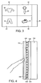
- the type of touch screen 6 with which an embodiment of the present invention is concerned is shown in Figure 4.
- Figure 4 shows a resistive touch screen system.
- the resistive touch screen system consists of a glass panel 200 overlying the cathode ray tube display (CRT)150. The glass panel 200 is covered in a uniform resistive coating 300.
- a thick polyester cover sheet 600 is suspended over the resistive coating 300, separated by small transparent insulating dots 500.
- the surface of the coversheet facing the glass panel 200 is covered in a conductive coating 400.
- the opposite outer side of the coversheet 600 is covered in a scratch resistant coating 700.
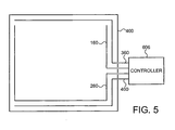
- Wires 160 and 260 detect the voltage produced by the touch along the x axis, whist wires 360 and 460 detect the voltage produced along the Y axis.
- the wires 160, 260, 360 and 460 are connected to an analogue to digital converter (not shown) which forms part of the touch screen controller 606.
- the analogue to digital converter converts the voltages into a digital signal.
- the controller 606 translates the signal into x and y coordinates to be sent to the CPU 100.
- the touch screen may serve as an interface to a number of services offered by the ordering system.
- the 'welcome screen' which is displayed on the touch screen to the shopper upon entering the changing room allows the user select a service from any of the services offered.
- the information relating to the scanned items is stored in the RAM together with the identification of the changing room to which the shopper has been directed. This information is processed by the CPU and output to the touch screen inside the changing room to which the shopper has been directed, such that the welcome screen displays, typographically and/or pictorially a representation of the items scanned at the scanning device 4.
- the touch screen may be further connected to a DVD or video player (not shown).
- the touch screen may then be arranged to play advertisements or visual entertainment.
- the touch screen may be arranged to play information from the DVD or video player after if has been determined that the touch screen has not been touched for a predetermined time.
- the touch screen may be arranged to play an audio and/or video welcome message when a shopper arrives in the changing room.
- Information relating to the items stocked by the shop are stored in the ROM of the CPU, or on a central database to which the CPU has access. This information may be stored in a variety of ways. In a preferred embodiment of the invention, this information may be stored in a series of look up tables. Each look up table may store the identification of items relating to a particular attribute. For example, the styles of items having a particular colour or size. Alternatively or additionally, look up tables may store information relating to a particular type of item. This may include an indication of whether or not a particular item is in stock, or whether complementary items, such as matching accessories are available.
- figure 3 shows a touch screen display that may be presented to the shopper upon entering the changing room. This initial display may be referred to as a 'welcome screen'.
- the display shows a pictorial representation of the items scanned in at the scanning device 4.
- a picture of a jumper 38 is displayed in the upper left hand quadrant 30 of the display, a picture of a tie 42 is shown in the upper right hand quadrant 32 of the display, a picture of trousers 40 are shown in the lower left hand quadrant 34 of the display and a picture of a pair of shoes 44 are shown in the lower right hand quadrant 36 of the display.
- Information relating to any of the items shown on the display is selectable by touching the region of the display in which the item is shown.
- the touch screen can be arranged to provide instructions to the user on how to use the system, including to touch a region of the display to obtain information on an item.
- the jumper is selectable by touching the upper left hand quadrant 30 of the display.
- quadrant 30 is touched when the welcome screen shown in figure 3 is displayed, the controller 606 generates the coordinates of the position of the touch and sends them to the CPU 100.
- the coordinates of the touch and the type of display, in this case the welcome screen are used as variables for a program stored in the ROM which enables the shopper to navigate through the selection of screen options.
- the program recognises that the coordinates of the touch on the touch screen relate to a jumper of a particular style, size and colour and coordinating items.
- the program retrieves information relating to alternative sizes, colours or styles of the jumper. This information may be presented to the shopper at once by displaying the information together, or by allowing the shopper to specify what information he wishes to see by presenting different options on the touch screen.
- the shopper may touch a region of the screen to have such items displayed, and to touch the screen again to go back to the former display.
- the system may also present the shopper with a tabbed window display, including information on other aspects of a product, including, for example, comments from the product's designer.
- the shopper may order the item by selecting the item and a desired size thereof using the touch screen.
- the CPU relays the request to the stock room display 22.
- the display shows a representation of the ordered item, together with the source of the request, i.e. the identification of the particular changing room.
- a further screen may be provided in each changing room.
- This screen will be hereinafter referred to as an activity screen 81 and is shown in figure 8.
- the purpose of the activity screen is to show the shopper what he or she has in the changing room in as well as what he or she has ordered using the touch screen.
- the activity screen is divided into three main sections: a first section 82 lists either pictorially or typographically, the items that the shopper has in the changing room and/or has ordered; the second section 83 indicates whether the item listed in section 81 is presently in the changing room, whether the item has been ordered but has not yet arrived, or whether the ordered item has been delivered; finally the third section 84 indicates the price of the items shown in section 82. Section 84 may further display the total price of the items that the shopper has in the changing room and/or has ordered.
- Staff located in the stockroom 13 respond to orders shown on the stockroom display 22 as soon as a request is received, by either retrieving the item from the stockroom or the shop floor, or by responding to the shopper via stockroom input means 24.
- the staff on the shop floor may alternatively be provided with wireless terminals that can display the order. If the item has sold out, a member of staff in the stockroom may indicate this to the shopper by inputting a message into the stockroom input means 24. This message is relayed to the touch screen from which the request was made via the CPU.
- the stockroom input means may be used to input information indicating that an item has sold out as soon as a member of staff is aware of that the item has sold out.
- the CPU 100 may be connected to a database (not shown) that stores a real time indication of the stock in the store. Stock levels stored on the database may be incremented after a delivery of a particular item and decremented after a sale. This information may be stored in the RAM of the CPU so that a message may be generated by the CPU in reply to a request for an item that has sold out.
- FIG. 6 shows an arrangement in accordance with an embodiment of the present invention for delivering items into the changing room.
- the entrance 70 to the changing room, through which the shopper enters is concealed by two sets of doors, comprising an inner set 72 and an outer set 74.
- the shopper enters the changing room by opening both sets of doors.
- the member of staff may deliver the items by opening the outer doors only and depositing the item between the doors. For example the item may be hung on a hook which protrudes from the surface of the inner door which faces the outer set of doors.
- the member of staff may indicate to the shopper that the item has been delivered by activating an indicator such as a buzzer or a light or a message on the touch screen 6. Alternatively a voice message may be played to the shopper announcing that the item(s) have arrived.
- a switch is preferably provided outside and adjacent to the changing room whereby the member of staff may activate the indicator.
- the shopper may then open the inner doors to retrieve the item.
- a switch may be provided inside the changing room whereby the indicator may be cancelled by the shopper; alternatively the program that is executed by the CPU may be arranged so that the shopper can cancel the indicator by means of the touch screen, or the indicator may be deactivated after a predetermined time.
- the CPU will be arranged to indicate to the activity screen that the ordered item has been delivered.
- the activity screen may then change the displayed status of the item accordingly.
- a further bar code scanner may be provided in the proximity of the changing room. This would allow the data relating to the delivered items to be captured and input to the ROM of the CPU. The information may then be presented to the shopper on the touch screen. If the further bar code scanner is placed by the delivery entrance to the changing room, the member of staff may scan the delivered items before placing them inside the outer set of doors as described above. Alternatively, the further bar code scanner may be placed inside the changing room so that the shopper may scan the delivered items himself.
- the member of staff who delivers and removes items from the changing room may be provided with a terminal that incorporates a scanner for scanning the barcode on the items.
- a scanner for scanning the barcode on the items.
- the member of staff can scan the item to indicate to a central database that a particular item has either been delivered or removed from a particular changing room.
- the doors may also function as an arrangement for returning unwanted items to prevent the changing room from becoming cluttered with items. This may be achieved by the member of staff collecting all items which are left in between the inner and outer doors when the items are being delivered. A window may be provided on an outer door 74, so that a member of staff may see when unwanted items are ready for collection. Alternatively, a member of staff may intermittently check in between the doors for returned items. The returned items may be distinguished from delivered items which have not yet been collected by the shopper by hanging returned items on a separate hook to delivered items. To allow this to be done, two zones for receiving articles may be provided between the doors. One zone is intended for receiving delivered items and one zone is intended for receiving returned items. Each zone may be identified by a sign at the zone. Each zone may have one or more hooks, shelves or other receptacles for receiving items.
- the shopper and the members of staff may distinguish between items that have been delivered to the changing room and items that are to be returned by using different coloured hangers. For example, items that have been delivered to the changing room may be placed on green hangers and items that are to be collected from the changing room may be placed on red hangers.
- the shopper may place unwanted items on a hook which makes electrical contact with a switch.
- the switch may activate an indicator that indicates to members of staff that there are unwanted items in the changing room that are ready for collection. When the member of staff retrieves the items from the hook, electrical contact with the switch is broken and the indicator is deactivated.
- the member of staff may scan each item that they collect from the changing room in order to indicate to the activity screen and the shopper that the item is no longer in the changing room.
- the retailer may be provided with information on how many items are in a changing room at a particular time. This may assist security procedures in the shop. For example, in an embodiment of the present invention, on exiting the changing room the shopper may be asked to take all the remaining clothes from the changing room and asked which items they wish to purchase and which items they wish to return. If the amount of items taken from the changing room by the shopper do not tally with the information provided by the ordering system relating to the number of clothes in the changing room, the situation may be investigated further.
- FIG 7 An alternative arrangement to the delivery system shown in figure 6 is shown in figure 7.
- the shopper enters the changing room through a single set of doors 82 which are arranged to provide access to the changing room from the changing room area 8.
- the delivery arrangement comprising an inner set of doors 72' and an outer set of doors 74' is arranged to provide a separate access to the changing room from the service corridor 18.
- the delivery arrangement is on the opposite side of the changing room to the single set of doors 82. Delivery of items through the delivery arrangement occurs in the same manner as described in relation to figure 6.
- Providing a delivery access arranged between the changing room and the service corridor allows a member of staff to deliver the ordered item to the shopper without having to enter the changing area. This allows the items to be transferred to the changing room more efficiently.
- a vestibule 73 between the inner and outer doors 72/72' and 74 /74'. Since it is expected that a member of staff may access the vestibule to bring or take items of clothing, it is preferred that means are provided to prevent both the inner and outer doors from being opened simultaneously whilst a shopper is in the changing room. Such means could be mechanical (for example a latch operable from inside the changing room) or electrical (for example an electromagnetic or electromechanical interlock system operable by a switch in the changing room). Nevertheless, in most instances it will be most convenient for the shopper to open both the inner and outer doors on leaving the changing room.
- information processed by the ordering system such as the number of changing rooms occupied at a given time may be used by the retailer to determine the proportion of time the changing rooms are occupied for. This information may help the retailer to determine whether the number of changing rooms provided in a particular retail outlet are sufficient.
Landscapes
- Management, Administration, Business Operations System, And Electronic Commerce (AREA)
- Sorption Type Refrigeration Machines (AREA)
- Magnetic Treatment Devices (AREA)
- Stabilization Of Oscillater, Synchronisation, Frequency Synthesizers (AREA)
- Input From Keyboards Or The Like (AREA)
Claims (17)
- Anproberaum mit:einem Datenspeicher zum Speichern der Eigenschaften mehrerer Einzelwaren;einer Eingabevorrichtung (4) zum Empfangen der Kennung einer Einzelware;einer Anzeige- und Eingabeeinrichtung (6), die sich im Anproberaum (16) befindet;einer Steuerungseinrichtung, die so ausgebildet ist, dass sie eine Eingabe von der Eingabevorrichtung (4) und der Eingabeeinrichtung (6) erhält, Daten aus dem Datenspeicher heraussucht und die Anzeige (6) steuert;
wobeidie Steuerungseinrichtung dafür sorgt, dass eine Eigenschaft einer Einzelware auf der Anzeige angezeigt wird;eine Person im Anproberaum über die Eingabeeinrichtung eine auf der Anzeige angezeigte Eigenschaft auswählen kann;die Steuerungseinrichtung so ausgebildet ist, dass sie dafür sorgt, dass die Anzeige eine Wahlmöglichkeit zum Bestellen einer Einzelware mit einer ähnlichen Eigenschaft anzeigt, und sie, auf die Auswahl der Wahlmöglichkeit zum Bestellen einer Einzelware hin, einen Befehl zum Liefern der Einzelware an den Anproberaum ausgibt. - Anproberaum nach Anspruch 1, bei dem eine Meldung an die Anzeigeeinrichtung weitergeleitet wird, dass eine Einzelware nicht auf Lager ist.
- Anproberaum nach Anspruch 1 oder Anspruch 2, ferner mit:einer ersten Öffnung (2), durch die ein Kunde in den Anproberaum gelangen kann; undeiner zweiten Öffnung, durch die Waren in den Anproberaum geliefert werden können; undeiner Zuführanordnung, die sich an der zweiten Öffnung befindet und über eine erste Konfiguration, in der sie Güter von außerhalb des Anproberaums empfangen kann, und eine zweite Konfiguration verfügt, in der in der Anordnung aufgenommene Güter vom Inneren des Anproberaums zugänglich sind.
- Anproberaum nach einem der Ansprüche 1 bis 3, bei dem die genannte Eigenschaft das äußere Aussehen ist.
- Anproberaum nach einem der vorstehenden Ansprüche, bei dem die Steuerungseinrichtung so ausgebildet ist, dass sie den Speicher nach Waren mit mindestens einer Eigenschaft, die den Einzelwaren gemeinsam ist, und mindestens einer Eigenschaft, die den Einzelwaren nicht gemeinsam ist, durchsucht, um eine Eigenschaft für jede dieser Einzelwaren herauszusuchen und dafür zu sorgen, dass sie auf der Anzeige angezeigt wird.
- Anproberaum nach Anspruch 5, bei dem zu den Eigenschaften zwei oder mehr der Eigenschaften Größe, Farbe und Stil gehören.
- Anproberaum nach einem der vorstehenden Ansprüche, bei dem die Auswähleinrichtung und die Anzeige durch einen Berührungsschirm gebildet sind.
- Anproberaum nach einem der vorstehenden Ansprüche, bei dem die Eigenschaft eine von mehreren auf der Anzeige angezeigten Eigenschaften ist.
- Anproberaum nach einem der vorstehenden Ansprüche in Abhängigkeit vom Anspruch 5 oder 6, bei dem die ausgewählte Eigenschaft die nicht gemeinsame Eigenschaft ist.
- Anproberaum nach einem der vorstehenden Ansprüche in Abhängigkeit vom Anspruch 3, bei dem die Zuführanordnung über eine zweite Eingabevorrichtung verfügt, die mit der Steuerungseinrichtung verbunden ist, und die Steuerungseinrichtung so ausgebildet ist, dass sie, auf die Bedienung der zweiten Eingabevorrichtung hin, dafür sorgt, dass die Anzeige die Verfügbarkeit einer Einzelware in der Zuführanordnung angibt.
- Anproberaum nach einem der vorstehenden Ansprüche, bei dem die Eingabevorrichtung über eine Scanvorrichtung verfügt.
- Anproberaum nach Anspruch 11, bei dem die Eingabevorrichtung über eine Strichcode-Scanvorrichtung verfügt.
- Anproberaum nach einem der vorstehenden Ansprüche in Abhängigkeit vom Anspruch 3, bei dem die Zuführanordnung so ausgebildet ist, dass sie die zweite Öffnung in der ersten und zweiten Konfiguration verdeckt.
- Anproberaum nach einem der vorstehenden Ansprüche in Abhängigkeit vom Anspruch 3, bei dem die Zuführanordnung über einen Raum und eine erste Tür zwischen dem Raum und dem Inneren des Anproberaums sowie eine zweite Tür zwischen dem Raum und dem Äußeren des Anproberaums verfügt.
- Anproberaum nach Anspruch 14, bei dem sich im Raum zum Aufnehmen von Einzelwaren zur Lieferung in das Innere des Anproberaums eine erste Zone befindet und sich im Raum zum Aufnehmen von Einzelwaren zur Ausgabe aus dem Anproberaum eine zweite Zone befindet.
- Anproberaum nach Anspruch 15, bei dem sich in der ersten Zone ein erster Haken zum Aufnehmen von Einzelwaren befindet, und sich in der zweiten Zone ein zweiter Haken zum Aufnehmen von Einzelwaren befindet, wobei sowohl der erste als auch der zweite Haken an einer der ersten und der zweiten Tür montiert sind.
- Anproberaum nach einem der Ansprüche 14 bis 18, bei dem sowohl die erste als auch die zweite Tür nicht durchsichtig sind.
Applications Claiming Priority (3)
| Application Number | Priority Date | Filing Date | Title |
|---|---|---|---|
| GB0223319 | 2002-10-08 | ||
| GB0223319A GB2394339A (en) | 2002-10-08 | 2002-10-08 | An automatic ordering system for supplying garments to a changing room |
| PCT/GB2003/004356 WO2004032690A1 (en) | 2002-10-08 | 2003-10-08 | Changing room |
Publications (2)
| Publication Number | Publication Date |
|---|---|
| EP1558117A1 EP1558117A1 (de) | 2005-08-03 |
| EP1558117B1 true EP1558117B1 (de) | 2006-12-06 |
Family
ID=9945497
Family Applications (1)
| Application Number | Title | Priority Date | Filing Date |
|---|---|---|---|
| EP03751040A Expired - Lifetime EP1558117B1 (de) | 2002-10-08 | 2003-10-08 | Anproberaum |
Country Status (10)
| Country | Link |
|---|---|
| US (1) | US20060004592A1 (de) |
| EP (1) | EP1558117B1 (de) |
| JP (1) | JP2006504886A (de) |
| AT (1) | ATE347296T1 (de) |
| AU (1) | AU2003269262A1 (de) |
| CA (1) | CA2501761A1 (de) |
| DE (1) | DE60310253T2 (de) |
| ES (1) | ES2278186T3 (de) |
| GB (1) | GB2394339A (de) |
| WO (1) | WO2004032690A1 (de) |
Families Citing this family (15)
| Publication number | Priority date | Publication date | Assignee | Title |
|---|---|---|---|---|
| GB0522835D0 (en) * | 2005-11-09 | 2005-12-21 | Johnson Paul R | Changing room system |
| US8760416B2 (en) * | 2009-10-02 | 2014-06-24 | Dedo Interactive, Inc. | Universal touch input driver |
| WO2011089452A1 (en) * | 2010-01-20 | 2011-07-28 | Ivana Marsic | Multimedia system for shopping process management |
| ITPD20110196A1 (it) * | 2011-06-14 | 2012-12-15 | Editek Di Fontanive Adriano & C S A S | Cabina di prova per capi di abbigliamento e relativo metodo di prova di un capo di abbigliamento |
| US20130334309A1 (en) * | 2012-06-17 | 2013-12-19 | Hointer, Inc. | Method and system for selling items to be worn |
| US10235710B2 (en) * | 2013-06-25 | 2019-03-19 | Sears Brands, L.L.C. | Systems and methods for scanning items and delivery to fitting room |
| JPWO2015125455A1 (ja) * | 2014-02-20 | 2017-03-30 | 日本電気株式会社 | 販売支援装置、販売システム、販売支援方法、及び、プログラム |
| ES2545681B1 (es) * | 2014-03-11 | 2016-06-21 | Jogo Tech, S.L. | Sistema para la optimización de probadores |
| JP5851560B2 (ja) * | 2014-07-09 | 2016-02-03 | 株式会社Six | 情報処理システム |
| JP6105135B1 (ja) * | 2016-07-15 | 2017-03-29 | 株式会社リクルートホールディングス | 試着効率化システム |
| WO2018048902A1 (en) | 2016-09-06 | 2018-03-15 | Platform Orthopedic Solutions Inc | A system, platform, device and method for personalized shopping |
| KR102643553B1 (ko) * | 2017-01-06 | 2024-03-05 | 나이키 이노베이트 씨.브이. | 자동 쇼핑 어시스턴트를 이용한 개인화 쇼핑을 위한 시스템, 플랫폼 및 방법 |
| US11763365B2 (en) | 2017-06-27 | 2023-09-19 | Nike, Inc. | System, platform and method for personalized shopping using an automated shopping assistant |
| US12211076B2 (en) | 2018-01-24 | 2025-01-28 | Nike, Inc. | System, platform and method for personalized shopping using a virtual shopping assistant |
| JP6942765B2 (ja) * | 2019-08-22 | 2021-09-29 | 東芝テック株式会社 | ユーザ端末、買物支援方法、買物支援プログラム |
Family Cites Families (9)
| Publication number | Priority date | Publication date | Assignee | Title |
|---|---|---|---|---|
| JPH07107718B2 (ja) * | 1987-10-13 | 1995-11-15 | 株式会社イトーキクレビオ | 貸し更衣室システム |
| US5551021A (en) * | 1993-07-30 | 1996-08-27 | Olympus Optical Co., Ltd. | Image storing managing apparatus and method for retreiving and displaying merchandise and customer specific sales information |
| US6182871B1 (en) * | 1995-01-19 | 2001-02-06 | Peter Ar-Fu Lam | Personalized garment coordination apparatus |
| ITMI952665A1 (it) * | 1995-12-19 | 1997-06-19 | Marazzi Ceramica | Metodo di gestione e sistema elettronico di vendita guidata di prodotti in un negozio |
| JPH09305356A (ja) * | 1996-05-14 | 1997-11-28 | Brother Ind Ltd | 電子カタログ装置 |
| WO2001045029A2 (en) * | 1999-12-10 | 2001-06-21 | Lennon Jerry W | Customer image capture and use thereof in a retailing system |
| US6313745B1 (en) * | 2000-01-06 | 2001-11-06 | Fujitsu Limited | System and method for fitting room merchandise item recognition using wireless tag |
| WO2001071447A2 (de) * | 2000-03-21 | 2001-09-27 | Beck Helga | Anordnung zur automatisierten online-warenbestellung |
| JP2002163722A (ja) * | 2000-11-29 | 2002-06-07 | Kojima Co Ltd | 商品販売管理方法および装置ならびに携帯端末 |
-
2002
- 2002-10-08 GB GB0223319A patent/GB2394339A/en not_active Withdrawn
-
2003
- 2003-10-08 ES ES03751040T patent/ES2278186T3/es not_active Expired - Lifetime
- 2003-10-08 DE DE60310253T patent/DE60310253T2/de not_active Expired - Fee Related
- 2003-10-08 AU AU2003269262A patent/AU2003269262A1/en not_active Abandoned
- 2003-10-08 WO PCT/GB2003/004356 patent/WO2004032690A1/en not_active Ceased
- 2003-10-08 CA CA002501761A patent/CA2501761A1/en not_active Abandoned
- 2003-10-08 EP EP03751040A patent/EP1558117B1/de not_active Expired - Lifetime
- 2003-10-08 AT AT03751040T patent/ATE347296T1/de not_active IP Right Cessation
- 2003-10-08 JP JP2004542633A patent/JP2006504886A/ja active Pending
-
2005
- 2005-04-08 US US10/907,639 patent/US20060004592A1/en not_active Abandoned
Also Published As
| Publication number | Publication date |
|---|---|
| GB0223319D0 (en) | 2002-11-13 |
| CA2501761A1 (en) | 2004-04-22 |
| AU2003269262A1 (en) | 2004-05-04 |
| ES2278186T3 (es) | 2007-08-01 |
| US20060004592A1 (en) | 2006-01-05 |
| WO2004032690A1 (en) | 2004-04-22 |
| DE60310253T2 (de) | 2007-06-28 |
| ATE347296T1 (de) | 2006-12-15 |
| GB2394339A (en) | 2004-04-21 |
| EP1558117A1 (de) | 2005-08-03 |
| JP2006504886A (ja) | 2006-02-09 |
| DE60310253D1 (de) | 2007-01-18 |
Similar Documents
| Publication | Publication Date | Title |
|---|---|---|
| US20060004592A1 (en) | Changing room | |
| KR100719073B1 (ko) | 음식점용 접객관리장치 | |
| US7496526B2 (en) | Method and system for selling clothes | |
| JP2006039748A (ja) | レストラン支援システム | |
| US6182795B1 (en) | Method for mobile sales and vehicles therefore | |
| EP1372092A1 (de) | Interaktiver Anproberaum | |
| US10540702B2 (en) | System for interactive marketing in reconfigurable vendor space | |
| JP2008304127A (ja) | 食品在庫管理システム | |
| US20030177069A1 (en) | Real time inventory display and retail sales system | |
| JP2019185221A (ja) | 店舗管理方法及び店舗管理システム | |
| KR20190136479A (ko) | 셀프 테이크아웃 시스템 | |
| JP3382476B2 (ja) | 厨房用表示装置 | |
| JP7213985B2 (ja) | 商品管理システム、ユーザ通信装置、商品管理装置、器具通信装置、及びプログラム | |
| US20210117913A1 (en) | Systems and methods for presenting and dispensing products | |
| JP3246719B2 (ja) | 厨房用表示装置 | |
| JP2022013371A (ja) | 商品受け渡しシステム | |
| JP2021081681A (ja) | 表示制御システム、表示制御方法 | |
| JP2003091554A (ja) | 情報選定表示システム | |
| JP2004280615A (ja) | 飲食店における飲食物告知発注システム | |
| US12333809B2 (en) | Systems and methods for locating a guest in a facility for order delivery | |
| US20250342697A1 (en) | Systems and methods for locating a guest in a facility for order delivery | |
| JP2003178165A (ja) | 売場案内システム | |
| EP4524871A1 (de) | Ein gerät zur präsentation und visualisierung von objekten, ein verfahren zur präsentation und visualisierung von objekten und zur erfassung von daten zum kundenverhalten und zu kundenpräferenzen | |
| JP7651890B2 (ja) | 物品自動引渡装置、物品自動引渡方法およびプログラム | |
| US20020016742A1 (en) | Retail system with purchase ordering |
Legal Events
| Date | Code | Title | Description |
|---|---|---|---|
| PUAI | Public reference made under article 153(3) epc to a published international application that has entered the european phase |
Free format text: ORIGINAL CODE: 0009012 |
|
| 17P | Request for examination filed |
Effective date: 20050415 |
|
| AK | Designated contracting states |
Kind code of ref document: A1 Designated state(s): AT BE BG CH CY CZ DE DK EE ES FI FR GB GR HU IE IT LI LU MC NL PT RO SE SI SK TR |
|
| AX | Request for extension of the european patent |
Extension state: AL LT LV MK |
|
| DAX | Request for extension of the european patent (deleted) | ||
| GRAP | Despatch of communication of intention to grant a patent |
Free format text: ORIGINAL CODE: EPIDOSNIGR1 |
|
| RIC1 | Information provided on ipc code assigned before grant |
Ipc: A47F 10/00 20060101AFI20060510BHEP |
|
| GRAS | Grant fee paid |
Free format text: ORIGINAL CODE: EPIDOSNIGR3 |
|
| GRAA | (expected) grant |
Free format text: ORIGINAL CODE: 0009210 |
|
| RAP1 | Party data changed (applicant data changed or rights of an application transferred) |
Owner name: RETELLIGENCE LIMITED |
|
| AK | Designated contracting states |
Kind code of ref document: B1 Designated state(s): AT BE BG CH CY CZ DE DK EE ES FI FR GB GR HU IE IT LI LU MC NL PT RO SE SI SK TR |
|
| PG25 | Lapsed in a contracting state [announced via postgrant information from national office to epo] |
Ref country code: IT Free format text: LAPSE BECAUSE OF FAILURE TO SUBMIT A TRANSLATION OF THE DESCRIPTION OR TO PAY THE FEE WITHIN THE PRESCRIBED TIME-LIMIT;WARNING: LAPSES OF ITALIAN PATENTS WITH EFFECTIVE DATE BEFORE 2007 MAY HAVE OCCURRED AT ANY TIME BEFORE 2007. THE CORRECT EFFECTIVE DATE MAY BE DIFFERENT FROM THE ONE RECORDED. Effective date: 20061206 Ref country code: DK Free format text: LAPSE BECAUSE OF FAILURE TO SUBMIT A TRANSLATION OF THE DESCRIPTION OR TO PAY THE FEE WITHIN THE PRESCRIBED TIME-LIMIT Effective date: 20061206 Ref country code: RO Free format text: LAPSE BECAUSE OF FAILURE TO SUBMIT A TRANSLATION OF THE DESCRIPTION OR TO PAY THE FEE WITHIN THE PRESCRIBED TIME-LIMIT Effective date: 20061206 Ref country code: BE Free format text: LAPSE BECAUSE OF FAILURE TO SUBMIT A TRANSLATION OF THE DESCRIPTION OR TO PAY THE FEE WITHIN THE PRESCRIBED TIME-LIMIT Effective date: 20061206 Ref country code: SK Free format text: LAPSE BECAUSE OF FAILURE TO SUBMIT A TRANSLATION OF THE DESCRIPTION OR TO PAY THE FEE WITHIN THE PRESCRIBED TIME-LIMIT Effective date: 20061206 Ref country code: CZ Free format text: LAPSE BECAUSE OF FAILURE TO SUBMIT A TRANSLATION OF THE DESCRIPTION OR TO PAY THE FEE WITHIN THE PRESCRIBED TIME-LIMIT Effective date: 20061206 Ref country code: LI Free format text: LAPSE BECAUSE OF FAILURE TO SUBMIT A TRANSLATION OF THE DESCRIPTION OR TO PAY THE FEE WITHIN THE PRESCRIBED TIME-LIMIT Effective date: 20061206 Ref country code: CH Free format text: LAPSE BECAUSE OF FAILURE TO SUBMIT A TRANSLATION OF THE DESCRIPTION OR TO PAY THE FEE WITHIN THE PRESCRIBED TIME-LIMIT Effective date: 20061206 Ref country code: NL Free format text: LAPSE BECAUSE OF FAILURE TO SUBMIT A TRANSLATION OF THE DESCRIPTION OR TO PAY THE FEE WITHIN THE PRESCRIBED TIME-LIMIT Effective date: 20061206 Ref country code: AT Free format text: LAPSE BECAUSE OF FAILURE TO SUBMIT A TRANSLATION OF THE DESCRIPTION OR TO PAY THE FEE WITHIN THE PRESCRIBED TIME-LIMIT Effective date: 20061206 Ref country code: SI Free format text: LAPSE BECAUSE OF FAILURE TO SUBMIT A TRANSLATION OF THE DESCRIPTION OR TO PAY THE FEE WITHIN THE PRESCRIBED TIME-LIMIT Effective date: 20061206 Ref country code: FI Free format text: LAPSE BECAUSE OF FAILURE TO SUBMIT A TRANSLATION OF THE DESCRIPTION OR TO PAY THE FEE WITHIN THE PRESCRIBED TIME-LIMIT Effective date: 20061206 |
|
| REG | Reference to a national code |
Ref country code: GB Ref legal event code: FG4D |
|
| REG | Reference to a national code |
Ref country code: CH Ref legal event code: EP |
|
| REG | Reference to a national code |
Ref country code: IE Ref legal event code: FG4D |
|
| REF | Corresponds to: |
Ref document number: 60310253 Country of ref document: DE Date of ref document: 20070118 Kind code of ref document: P |
|
| PG25 | Lapsed in a contracting state [announced via postgrant information from national office to epo] |
Ref country code: SE Free format text: LAPSE BECAUSE OF FAILURE TO SUBMIT A TRANSLATION OF THE DESCRIPTION OR TO PAY THE FEE WITHIN THE PRESCRIBED TIME-LIMIT Effective date: 20070306 Ref country code: BG Free format text: LAPSE BECAUSE OF FAILURE TO SUBMIT A TRANSLATION OF THE DESCRIPTION OR TO PAY THE FEE WITHIN THE PRESCRIBED TIME-LIMIT Effective date: 20070306 |
|
| PG25 | Lapsed in a contracting state [announced via postgrant information from national office to epo] |
Ref country code: PT Free format text: LAPSE BECAUSE OF FAILURE TO SUBMIT A TRANSLATION OF THE DESCRIPTION OR TO PAY THE FEE WITHIN THE PRESCRIBED TIME-LIMIT Effective date: 20070507 |
|
| NLV1 | Nl: lapsed or annulled due to failure to fulfill the requirements of art. 29p and 29m of the patents act | ||
| REG | Reference to a national code |
Ref country code: CH Ref legal event code: PL |
|
| EN | Fr: translation not filed | ||
| REG | Reference to a national code |
Ref country code: ES Ref legal event code: FG2A Ref document number: 2278186 Country of ref document: ES Kind code of ref document: T3 |
|
| PLBE | No opposition filed within time limit |
Free format text: ORIGINAL CODE: 0009261 |
|
| STAA | Information on the status of an ep patent application or granted ep patent |
Free format text: STATUS: NO OPPOSITION FILED WITHIN TIME LIMIT |
|
| 26N | No opposition filed |
Effective date: 20070907 |
|
| PG25 | Lapsed in a contracting state [announced via postgrant information from national office to epo] |
Ref country code: GR Free format text: LAPSE BECAUSE OF FAILURE TO SUBMIT A TRANSLATION OF THE DESCRIPTION OR TO PAY THE FEE WITHIN THE PRESCRIBED TIME-LIMIT Effective date: 20070307 Ref country code: FR Free format text: LAPSE BECAUSE OF FAILURE TO SUBMIT A TRANSLATION OF THE DESCRIPTION OR TO PAY THE FEE WITHIN THE PRESCRIBED TIME-LIMIT Effective date: 20070727 |
|
| PG25 | Lapsed in a contracting state [announced via postgrant information from national office to epo] |
Ref country code: MC Free format text: LAPSE BECAUSE OF NON-PAYMENT OF DUE FEES Effective date: 20071031 |
|
| PG25 | Lapsed in a contracting state [announced via postgrant information from national office to epo] |
Ref country code: DE Free format text: LAPSE BECAUSE OF NON-PAYMENT OF DUE FEES Effective date: 20080501 |
|
| PG25 | Lapsed in a contracting state [announced via postgrant information from national office to epo] |
Ref country code: FR Free format text: LAPSE BECAUSE OF FAILURE TO SUBMIT A TRANSLATION OF THE DESCRIPTION OR TO PAY THE FEE WITHIN THE PRESCRIBED TIME-LIMIT Effective date: 20061206 |
|
| REG | Reference to a national code |
Ref country code: ES Ref legal event code: FD2A Effective date: 20071009 |
|
| PG25 | Lapsed in a contracting state [announced via postgrant information from national office to epo] |
Ref country code: EE Free format text: LAPSE BECAUSE OF FAILURE TO SUBMIT A TRANSLATION OF THE DESCRIPTION OR TO PAY THE FEE WITHIN THE PRESCRIBED TIME-LIMIT Effective date: 20061206 |
|
| PG25 | Lapsed in a contracting state [announced via postgrant information from national office to epo] |
Ref country code: ES Free format text: LAPSE BECAUSE OF NON-PAYMENT OF DUE FEES Effective date: 20071009 |
|
| PGFP | Annual fee paid to national office [announced via postgrant information from national office to epo] |
Ref country code: GB Payment date: 20081103 Year of fee payment: 6 |
|
| PG25 | Lapsed in a contracting state [announced via postgrant information from national office to epo] |
Ref country code: CY Free format text: LAPSE BECAUSE OF FAILURE TO SUBMIT A TRANSLATION OF THE DESCRIPTION OR TO PAY THE FEE WITHIN THE PRESCRIBED TIME-LIMIT Effective date: 20061206 Ref country code: LU Free format text: LAPSE BECAUSE OF NON-PAYMENT OF DUE FEES Effective date: 20071008 |
|
| PG25 | Lapsed in a contracting state [announced via postgrant information from national office to epo] |
Ref country code: TR Free format text: LAPSE BECAUSE OF FAILURE TO SUBMIT A TRANSLATION OF THE DESCRIPTION OR TO PAY THE FEE WITHIN THE PRESCRIBED TIME-LIMIT Effective date: 20061206 Ref country code: HU Free format text: LAPSE BECAUSE OF FAILURE TO SUBMIT A TRANSLATION OF THE DESCRIPTION OR TO PAY THE FEE WITHIN THE PRESCRIBED TIME-LIMIT Effective date: 20070607 |
|
| PGFP | Annual fee paid to national office [announced via postgrant information from national office to epo] |
Ref country code: IE Payment date: 20100315 Year of fee payment: 7 |
|
| PG25 | Lapsed in a contracting state [announced via postgrant information from national office to epo] |
Ref country code: GB Free format text: LAPSE BECAUSE OF NON-PAYMENT OF DUE FEES Effective date: 20091008 |
|
| PG25 | Lapsed in a contracting state [announced via postgrant information from national office to epo] |
Ref country code: IE Free format text: LAPSE BECAUSE OF NON-PAYMENT OF DUE FEES Effective date: 20101008 |