EP1557856A2 - Method of manufacturing airtight vessel, and method of manufacturing image displaying apparatus - Google Patents
Method of manufacturing airtight vessel, and method of manufacturing image displaying apparatus Download PDFInfo
- Publication number
- EP1557856A2 EP1557856A2 EP05000065A EP05000065A EP1557856A2 EP 1557856 A2 EP1557856 A2 EP 1557856A2 EP 05000065 A EP05000065 A EP 05000065A EP 05000065 A EP05000065 A EP 05000065A EP 1557856 A2 EP1557856 A2 EP 1557856A2
- Authority
- EP
- European Patent Office
- Prior art keywords
- frame member
- substrates
- manufacturing
- frame
- prescribed
- Prior art date
- Legal status (The legal status is an assumption and is not a legal conclusion. Google has not performed a legal analysis and makes no representation as to the accuracy of the status listed.)
- Withdrawn
Links
Images


Classifications
-
- H—ELECTRICITY
- H01—ELECTRIC ELEMENTS
- H01J—ELECTRIC DISCHARGE TUBES OR DISCHARGE LAMPS
- H01J9/00—Apparatus or processes specially adapted for the manufacture, installation, removal, maintenance of electric discharge tubes, discharge lamps, or parts thereof; Recovery of material from discharge tubes or lamps
- H01J9/24—Manufacture or joining of vessels, leading-in conductors or bases
- H01J9/26—Sealing together parts of vessels
- H01J9/261—Sealing together parts of vessels the vessel being for a flat panel display
-
- F—MECHANICAL ENGINEERING; LIGHTING; HEATING; WEAPONS; BLASTING
- F24—HEATING; RANGES; VENTILATING
- F24F—AIR-CONDITIONING; AIR-HUMIDIFICATION; VENTILATION; USE OF AIR CURRENTS FOR SCREENING
- F24F13/00—Details common to, or for air-conditioning, air-humidification, ventilation or use of air currents for screening
- F24F13/28—Arrangement or mounting of filters
-
- F—MECHANICAL ENGINEERING; LIGHTING; HEATING; WEAPONS; BLASTING
- F24—HEATING; RANGES; VENTILATING
- F24F—AIR-CONDITIONING; AIR-HUMIDIFICATION; VENTILATION; USE OF AIR CURRENTS FOR SCREENING
- F24F7/00—Ventilation
- F24F7/04—Ventilation with ducting systems, e.g. by double walls; with natural circulation
-
- H—ELECTRICITY
- H01—ELECTRIC ELEMENTS
- H01J—ELECTRIC DISCHARGE TUBES OR DISCHARGE LAMPS
- H01J9/00—Apparatus or processes specially adapted for the manufacture, installation, removal, maintenance of electric discharge tubes, discharge lamps, or parts thereof; Recovery of material from discharge tubes or lamps
- H01J9/24—Manufacture or joining of vessels, leading-in conductors or bases
- H01J9/241—Manufacture or joining of vessels, leading-in conductors or bases the vessel being for a flat panel display
-
- F—MECHANICAL ENGINEERING; LIGHTING; HEATING; WEAPONS; BLASTING
- F24—HEATING; RANGES; VENTILATING
- F24F—AIR-CONDITIONING; AIR-HUMIDIFICATION; VENTILATION; USE OF AIR CURRENTS FOR SCREENING
- F24F7/00—Ventilation
- F24F2007/004—Natural ventilation using convection
Definitions
- the present invention relates to a method of manufacturing airtight vessel whose inside is to be kept airtight, and more particularly to a method of manufacturing airtight vessel which can be suitably applied to display panels of image displaying apparatus.
- the invention also relates to an image displaying apparatus, and a method of manufacturing image displaying apparatus. It also relates to a method of manufacturing television sets.
- an image displaying apparatus utilizing electron emission requires an envelope for maintaining a vacuum ambience, an electron source provided with a plurality of electron-emitting devices and a drive circuit therefor, an image-forming member having a phosphor or the like which is caused to emit light by the collision of electrons, and accelerating electrodes for accelerating the motions of electrons towards the image-forming member and a voltage source or the like therefor.
- An image displaying apparatus using a flat envelope, such as a thin image displaying apparatus or the like may use supports (spacers) as structures to endure the atmospheric pressure.
- cold cathode devices include field-emission electron-emitting devices (hereinafter abbreviated to the FE type), metal/insulator/metal type electron-emitting devices (hereinafter abbreviated to the MIM type) and surface conduction electron-emitting devices.
- FIG. 10 schematically shows the configuration of an example of display panel of an image displaying apparatus using conventional surface conduction electron-emitting devices.
- reference numeral 103 denotes a rear plate; 104, an external frame and 110, a face plate.
- the rear plate 103, the external frame 104 and the face plate 110 constitute an envelope (airtight vessel) for keeping the inside of the display panel vacuum.
- An electron source substrate 101 is fixed to the rear plate 103, and N ⁇ M surface conduction electron-emitting devices 106 are formed over the electron source substrate 101 (N and M are positive integers not smaller than 2, whose number is appropriately set according to the intended number of display pixels).
- the N ⁇ M electron-emitting devices 106 are wired with MX-directional wires 102 and N Y-directional wires 105 as shown in FIG. 10. Between the X-directional wires 102 and the Y-directional wires 105, at least where they cross, an insulating layer (not shown) is formed to maintain electric insulation.
- a fluorescent film 108 consisting of phosphors is formed over the under face of the face plate 110, differentiated in color by phosphors (not shown) of three primary colors including red (R), green (G) and blue (B). Black components (not shown) are provided between the phosphors of different colors constituting the fluorescent film 108, and a metal back 107 consisting of A1 or the like is formed on the face of the fluorescent film 108 toward the rear plate 103.
- Dx1 through Dxm, Dy1 through Dyn and a high voltage terminal Hv are airtight-structured terminals for electrical connection, provided to electrically connect the display panel to an electrical circuit (not shown).
- Dx1 through Dxm are electrically connected to the X-directional wires 102 of the electron source, Dy1 through Dyn to the Y-directional wires 105 of the electron source, and Hv to the metal back 107.
- the inside of the envelope 111 is maintained in a vacuum of around 1.3 ⁇ 10 -4 Pa.
- the need increases for means to prevent deformation or destruction of the rear plate 103 and the face plate 110 due to the pressure difference between the inside and the outside of the envelope 111.
- Increasing the thicknesses of the rear plate 103 and the face plate 110 would not only make the image displaying apparatus heavier but also give rise to image distortion and parallax when the display panel is viewed obliquely.
- the configuration shown in FIG. 10 is provided with structural supports (known as spacers or ribs) 112 consisting of relatively thin glass plates and intended to stand the atmospheric pressure.
- the gap between the substrate 101 on which electron source is formed and the face plate 110 on which the fluorescent film 108 is formed is usually kept between sub-millimeters to a few millimeters, and the inside of the envelope 111 is kept at a high degree of vacuum.
- liquid crystal displays such as plasma displays and EL displays
- the internal space is defined by a frame, a face plate and a rear plate, the latter two being two members opposite each other, and a desired atmosphere is maintained in the internal space.
- a problem intended to be solved by at least part of the invention under the present application is to realize a method of manufacturing appropriate airtight vessel.
- the present inventor assessed the possibility of using a member smaller in sectional size (e.g. sectional width) as the member for use in the external frame with a view to reducing the size of the screen frame (non-display area) and the cost of members.
- a smaller sectional size of the frame member would result in insufficient mechanical rigidity.
- the frame would be unable to maintain its shape by itself.
- it would become difficult in assembling the panel to accurately align the external frame, which is the frame member, with desired positions in the face plate and the rear plate and assemble them. If the positional accuracy of the external frame is poor, the likelihood of impossibility to maintain a desired atmosphere in the internal space will increase, leading to a drop in yield.
- a method of manufacturing airtight vessel having two substrates and a frame portion fixed to the two substrates and forming a prescribed space between the two substrates comprising a step of keeping a frame member for the frame portion in a prescribed shape by applying a tension to at least part of the frame member for the frame portion, and a step of adhering the frame member to at least one of the substrates in a state in which the prescribed shape is kept.
- a method of manufacturing airtight vessel having two substrates and a frame portion fixed to the two substrates and forming a prescribed space between the two substrates comprising a step of airtightly adhering a frame member for the frame portion to the two substrates in a state in which the frame member is kept in a prescribed shape by a frame member position-restricting member.
- a method of manufacturing airtight vessel having two substrates and a frame portion fixed to the two substrates and forming a prescribed space between the two substrates comprising a step of keeping a frame member for the frame portion in a prescribed shape with a frame member position-restricting member for restricting the positions of the frame member in a state in which the frame portion is in contact with neither of the two substrates, and a step of adhering the frame member to at least one of the substrates.
- the method of manufacturing airtight vessel according to the invention include the following as preferable forms:
- the frame member is rectangular, and its four corners are supported by frame member position-restricting members.
- the frame member is rectangular, and one pair of opposite sides are more rigid than the other pair of opposite sides.
- the airtight vessel under the present application can be suitably applied to an image display apparatus, and the application includes an invention of an image display apparatus and an invention of a method of manufacturing the image display apparatus. It also includes a method of manufacturing an image display apparatus each using the image displaying apparatus.
- a method of manufacturing airtight vessel described below in the embodiment of the present invention uses frame member position-restricting member in adhering and fixing a frame member to substrates, so that the frame member is adhered while its shape is maintained as it should be.
- the step of adhering the frame member to the substrates may be executed either by adhering the frame member, after it is adhered to one of the substrates, to the other or by having the two substrates hold the frame member between them and adhering the frame member to both substrates at the same time.
- the two substrates for use in the invention may be members whose material and shape can be selected from various alternatives, usually insulating substrates, particularly glass substrates, are preferred for use in configuring a display panel.
- insulating substrates particularly glass substrates
- flat substrates of soda lime glass are used.
- Basic materials that can be used for the frame member include insulators and high resistors, but it is preferable to use the same material as that for the substrates.
- the adhesive for fixing the frame member to the substrates a preferable choice is a metal having a low melting point, more specifically In or some other metal or an alloy thereof, because it has to perform dual functions of keeping vacuum airtightness and adhesion to the glass substrates. Such an adhesive is softened by heating when it is applied.
- the adhesive is electroconductive, it can be heated by applying electricity, but the application of electricity should preferably be used in combination with some other means of heating. More specifically, heating by irradiation with an electromagnetic wave, heating by thermal conduction from a heat source, or combined use of the two is preferable.
- the two substrates that can be used in implementing the invention are subject to no limitation regarding the external shape of their main faces, but usually at least one of them is a planar member having an exactly or substantially rectangular (oblong or square) shape.
- the frame member is disposed in a shape substantially along the contours of these rectangular substrates or substantially along a shape formed by contracting this rectangle inward.
- the invention makes it possible to fabricate an airtight vessel by using a frame member which cannot maintain its shape by itself.
- the frame member in this context means a frame member whose shape cannot be maintained with required accuracy by holding only one position thereof.
- a rectangular frame member In order for a rectangular frame member to maintain its rectangular shape, it is desirable to define the positions of its four corners. Therefore in a preferable embodiment of the invention, it is desirable for the position-restricting member of the frame member to support and restrict the position of the frame member on flanks inside or outside its corners. It is also preferable to support at least two of the four sides of the frame member. In a preferable configuration, the desired shape is maintained by applying a tensile strength to each position of the frame member. In order to keep the rectangular or any other polygonal shape of the frame member, the tension should work on the sides of the frame member.
- the shape can be maintained in a state in which each side of the rectangle is subjected to a tensile strength by defining the positions of the four corners of the rectangular shape as mentioned above.
- a tension is applied to the part between two positions of each side by defining those two positions.
- Preferable two such positions are the two ends of the side. Since one defining position can be shared by two adjoining sides, four such defining positions are sufficient where a rectangle is to be maintained by applying a tension to each of its four sides.
- the supporting positions can be increased to more than four or a frame member whose section is not uniform but is expanded in area to partially strengthen the rigidity can be used.
- the frame member can be fabricated from the outset with its sectional area partially varied, or another member can be adhered to the part where the sectional area is to be expanded.
- the position-restricting members for the frame member either positioning members into which the frame member is fitted after it is fixed to one of the substrates and which support the fitted frame member or a jig which is fitted to the frame member and fixes the frame member to the substrates is used.
- the jig can be removed after the step of adhering and fixing the frame member to the substrates. In that case, part of the jig can be cut off and removed, and the rest may remain with the frame member.
- the basic material for the positioning members if they are to be fixed onto the substrates, to be a material close to that of the substrates in thermal expansion coefficient, or more preferably the same as the material of the substrates, with a view to harmonizing their thermal expansion with those of the substrates. Therefore, where the substrates are made of glass, preferably the positioning members should also be made of glass. Regarding the jig, since its shape is complex, desirably it should be made of a material which readily allows machining and is close to the substrate material in thermal expansion coefficient. Where the substrates are made of glass, the preferable material is an Ne-Ni alloy.
- reference numeral 1 denotes a face plate; 2, an image display area; 3, a rear plate; 4, an electron source area; 5 and 6, extraction wirings; 7, positioning members; 8, a frame member; 11, an adhesion layer; 12a and 12b, low melting-point metal layers; 13a through 13c, base layers; and 14, an insulating layer.
- FIG. 4B shows the A-A' section of FIG. 4A. Incidentally, the illustration of the insulating layer 14, the base layers 13a, 13b and 13c, and the low melting-point metal layer 12a is dispensed with in FIG. 4A.
- the face plate 1, the rear plate 3 and the frame member respectively correspond to the face plate 110, the rear plate 103 and the external frame 104 of the display panel in FIG. 10.
- the image display area 2 of the face plate 1 consists of a fluorescent film (not shown), black stripes (or a black matrix) and a metal back.
- the fluorescent film When the fluorescent film is monochrome, it can be configured of a phosphor alone, and when it is in color, it can be composed of black conductors known as black stripes or a black matrix and phosphors according to the array of the phosphors.
- the reasons for the use of the black stripes or black matrix are to make, in color displaying, any mixing of colors inconspicuous by blackening the boundaries between the phosphors of the three primary colors and to restrain any loss of contrast due to the reflection of external light by the fluorescent film.
- the black stripes are usually made of a material mainly consisting of graphite, but some other electroconductive material transmitting or reflecting less light can also be used.
- the fluorescent film can be formed by coating the image display area 2 with phosphors, irrespective of monochrome or color, by depositing, printing or otherwise.
- a metal back is usually provided on the inner side of the fluorescent film.
- the purposes of providing the metal back include improvement of luminance by bringing the inward part of the light emission from the phosphors to mirror reflection toward the face plate 1, causing it to serve as an electrode for applying an electron beam accelerating voltage, protection of the phosphors from being damaged by the collision of negative ions generated within the envelope.
- the metal back can be fabricated by smoothing the inner surface of the fluorescent film (usually referred to as "filming") after the formation of the fluorescent film and depositing A1 by vacuum evaporation or otherwise.
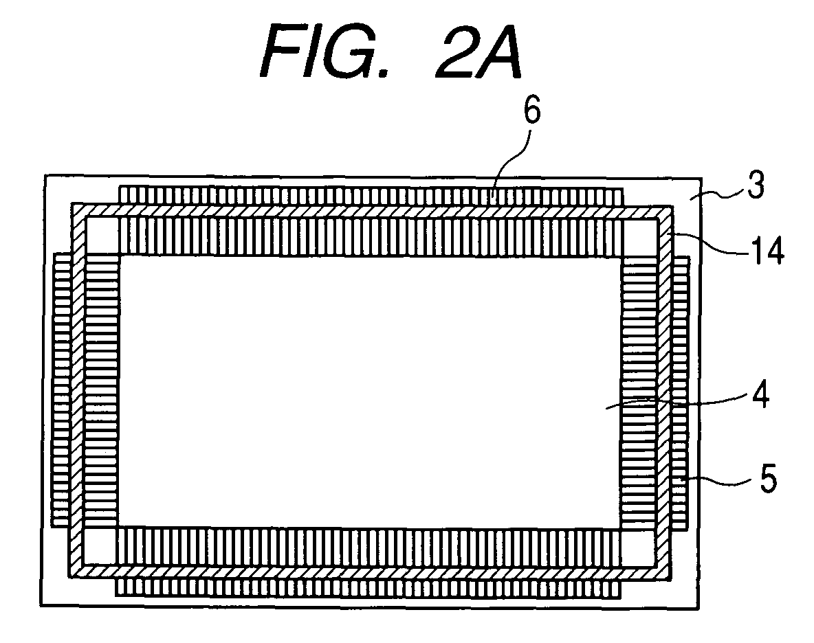
- the electron source area 4 is configured by arraying surface conduction electron-emitting devices (not shown), which are display devices, over the rear plate 3 in a matrix form as described in the Japanese Patent Application Laid-Open No. H7-235255, and the extraction wirings 5 and 6 are connected to the X-direction wiring (not shown) and the Y-direction wiring (not shown) and extracted to the end of the rear plate 3.
- the extraction wirings 5 and 6 can be formed over the rear plate 3 by patterning an A1 paste material by a known printing method and subjecting them to a baking process. Then, the glass component is shaped into a frame by a known printing method and baked to form the (FIG. 2A).
- An Ag paste is patterned by a known printing method over the insulating layer 14 shaped in a frame, and baked to constitute the base layer 13a. To insulate them from the extraction wirings 5 and 6, the base layer 13a is formed to be slight smaller in width than he insulating layer 14.
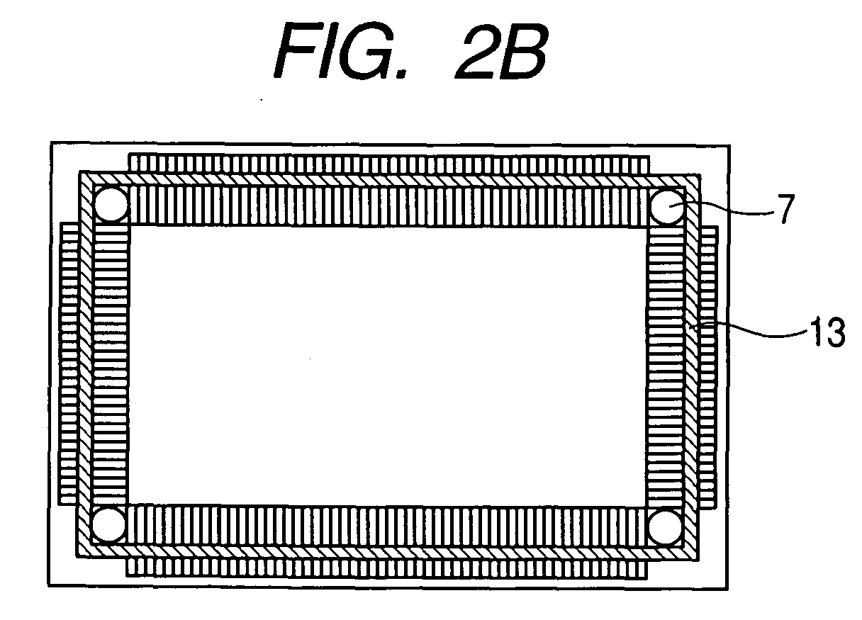
- the ceramic-made cylindrical positioning members 7 are adhered and fixed in the four corners, the positions where the frame member 8 is to be adhered, with the ceramic adhesion layer 11 (FIG. 2B).
- the positions of adhesion are adjusted to be appropriate (within the permissible range of the positional deviation of the frame member 8) with the inner dimensions of the frame member 8 and the external shape of the positioning members 7 taken into account.
- the heights of the positioning members 7 are kept lower than that of the frame member 8.
- a low melting-point metal is applied over the base layer 13a with a coating robot and an ultrasonic soldering iron to form the low melting-point metal layer 12a.
- the glass substrates are machined to form the frame member 8, and an Ag paste material is patterned by a known printing method and baked to constitute the base layer 13b.
- the frame member can also be punched out of a glass plate, or formed by welding glass rods constituting the four sides of the rectangular frame.
- the material of the frame member is not limited to glass, but the frame can as well be fabricated by shaping a thin rod, such as a wire, into a loop.
- the frame member 8, with its base layer 13b directed toward the rear plate 3 is positioned over the four positioning members 7 with a robot hand (not shown) which can keep it horizontal and provide a tension outward from each of the four corners of the frame member 8, and cautiously landed over the rear plate 3.
- the rectangular shape of the frame member 8 can be thereby kept in a state in which a tension is applied to each of its sides from one or another of the positioning members 7 (FIG. 2C).
- the base layer 13c is formed, followed by the low melting-point metal layer 12b, by the same processes as those for the base layers 13a and 13b and the low melting-point metal layer 12a (FIGS. 4A and 4B).
- the face plate 1 and the rear plate 3 are placed into a vacuum chamber (not shown) in which the substrates can be heated, aligned (X, Y) and subjected to spacing control. Within the vacuum chamber, the face plate 1 and the rear plate 3 are aligned with each other according to alignment marks (not shown) formed on those plates (FIG. 3). In this process, there is a gap between the face plate 1 and the rear plate 3, which accordingly are not in contact with each other. In this state, the temperatures of the face plate 1 and the rear plate 3 are raised with a substrate heating apparatus to the melting points of the low melting-point metal layers 12a and 12b.
- the face plate 1 and the rear plate 3 are brought close to each with a spacing control apparatus to cause the low melting-point metal layer 12b and the face plate are joined to each other, and so are the low melting-point metal layer 12a and the base layers 13a and 13b sandwiching it.
- This process should be carried out cautiously so that the low melting-point metal may not ooze out on the four sides of the frame member 8.
- the face plate 1 and the rear plate 3 are adhered to the frame member 8 to constitute an airtight vessel.
- the frame member 8 then is subjected to positional restriction by the positioning members 7, it can substantially maintain its initial position free from major positional deviations, and constitute a highly airtight vessel. Therefore, a highly reliable display panel can be provided for an image displaying apparatus in which images are formed by emitting electrons in a vacuum ambience.
- the materials and formation methods for the extraction wirings 5 and 6, the adhesion layer 11 and the insulating layer 14 and the material of the positioning member 7 are not limited to those stated above.
- a display panel 1101 has the airtight vessel configured as described above.
- a receiver circuit 1102 having the tuner selects television broadcast signals of a desired channel. Signals from the receiver circuit 1102 are entered into a control circuit 1103, where column drive signals and line drive signals are generated and supplied to a column drive signal and a row drive signal, and supplied to a column drive circuit 1104 and a row drive circuit 1105.
- the column drive signal is a modulating signal.
- the row drive signal is a scanning signal for sequentially selecting display lines on the display panel.
- a drive pulse based on the column drive signal is supplied by the column drive circuit 1104 to the display panel 1101.
- a drive pulse based on the row drive signal is supplied by the row drive circuit 1105 to the display panel 1101.
- the column drive circuit 1104 is connected to the display panel 1101 by using a flexible cable.
- the row drive circuit 1105 is also connected by using a flexible, cable.
- the control circuit 1103 is connected to the column drive circuit 1104 and the row drive circuit 1105, followed by connection of the receiver circuit 1102 and the control circuit.
- the television set can be fabricated in this way.
- FIG. 5 shows how the frame member 8 and the rear plate 3 are aligned with each other in a second embodiment of the invention.
- reference numeral 51 denotes positioning members, and the same members as in FIG. 3 are denoted by respectively the same reference signs.
- Each of the positioning members 51 consists of two ceramic-made cylindrical members linked to each other, but the two members may as well be separated from each other.
- the positioning members 51 are positioned in the four corners, each along two sides constituting one corner of the frame member 8, to perform positional restriction.
- This embodiment is more effective than the first embodiment for a display panel required to have a large screen because a large frame member 8 can be more securely subjected to positional restriction in this way.
- FIG. 6 shows how the frame member 8 and the rear plate 3 are aligned with each other in a third embodiment of the invention.
- reference numeral 61 denotes positioning pins, and, 62, fixing members.
- the same members as in FIG. 3 are denoted by respectively the same reference signs.
- This embodiment is the same as the first embodiment except that the positioning pins 61 and the fixing members 62 are used as positioning members and that the frame member 8 is subjected to positional restriction outside it. More specifically, holes bored in the fixing members 62 fitted outside the four corners of the frame member 8 are snapped with a robot hand (not shown) onto the positioning pins 61 fitted to the corners of the rear plate 3.
- the positioning pins 61 and the fixing members 62 should preferably be formed of ceramics.
- FIG. 7 shows how the frame member 8 and the rear plate 3 are aligned with each other in a fourth embodiment of the invention.
- the reference signs in FIG. 7 are the same as those in FIG. 6.
- This embodiment is the same as the first embodiment except that the frame member 8 is ladder-shaped, one pair of opposite sides 8b, made more rigid than the other pair of opposite sides 8a, the positioning pins 61 are used as positioning members, and the frame member 8 is subjected to positional restriction by them outside it.
- both ends of the sides 8b of the frame member 8 are supported by the positioning pins 61 and tensions work on the sides 8a to pull them in the lengthwise direction, but the more rigid sides 8b can well endure those tensions.
- the production cost can be reduced.
- FIG. 8 shows how the frame member 8 is supported by the frame member position-restricting members in a fifth embodiment of the invention.
- reference numeral 81 denotes a jig
- the same members as in FIG. 4 and FIG. 7 are denoted by respectively the same reference signs.
- This embodiment is the same as the first embodiment except that a jig 81 constitutes the frame member position-restricting members and the frame member 8 is ladder-shaped, consisting of more rigid elements 8b and less rigid elements 8a.
- the material of the jig 81 is matched with that of the rear plate 1 in consideration of thermal expansion arising during the assembling of the panel, and the jig 81 is caused to hold a more rigid member 8b to fix it to the rear plate 1. After the panel is assembled, the jig 81 can be removed.
- FIG. 9 shows how the frame member 8 is supported by the frame member position-restricting members in another embodiment of the invention.
- reference numeral 82 denotes the adhering portion of a jig, 83, the jig, and the same members as in FIGS. 4A and 4B are denoted by respectively the same reference signs.
- This embodiment is the same as the first embodiment except that the jig 83 constitutes the frame member position-restricting members, a low melting-point metal and a soldering iron are used to form the adhering portion 82, and the jig 83 is directly adhered and fixed to the frame member 8.
- the jig 83 is so structured as can be hooked on to an angular part of the rear plate 3.
- the frame member 9 while it is being handled, can be carried by picking up the jig 83, the design freedom of the carrying apparatus can be enhanced.
- a panel driving box grounding (not shown) and the adhering portion 82 can be connected to allow the jig to be used as a member to define the potential. Or it can as well be cut off in a desired position.
- the number, sizes and intra-facial positions of the frame member position-restricting members can be freely selected within the scope of the invention, and the substrate to which the frame member is adhered first can as well be used as the face plate 1.
- a display panel for an image displaying apparatus was fabricated in the first example.
- a face plate 1 having a fluorescent film and a metal back formed over soda lime glass substrates and a rear plate 3 consisting of surface conduction electron-emitting devices, disclosed in the Japanese Patent Application Laid-Open No. H7-235255, arranged in a matrix formed over the soda lime glass substrates was used.
- frame member 8 similar glass material to those of the face plate 1 and the rear plate 3 was used.
- a display panel for an image displaying apparatus was fabricated in the same way as Example 1 except that two ceramic-made cylindrical members of 8 mm in diameter and 1 mm in thickness, linked to each other by a low-thermal expansion metal rod, were used as the position-restricting members 51 in the second example.
- the present application discloses a method of manufacturing airtight vessel. More specifically, here is disclosed a method of manufacturing airtight vessel having two substrates, and a frame portion fixed to the two substrates and forming a prescribed space between the two substrates, the method comprising a step of keeping a frame member for the frame portion in a prescribed shape by applying a tension to at least a part of the frame member for the frame portion, and a step of adhering the frame member to at least one of the substrates in a state in which the prescribed shape is kept.
Landscapes
- Engineering & Computer Science (AREA)
- Manufacturing & Machinery (AREA)
- Chemical & Material Sciences (AREA)
- Combustion & Propulsion (AREA)
- Mechanical Engineering (AREA)
- General Engineering & Computer Science (AREA)
- Manufacture Of Electron Tubes, Discharge Lamp Vessels, Lead-In Wires, And The Like (AREA)
- Cathode-Ray Tubes And Fluorescent Screens For Display (AREA)
- Vessels, Lead-In Wires, Accessory Apparatuses For Cathode-Ray Tubes (AREA)
Abstract
Description
Claims (19)
- A method of manufacturing an airtight vessel having two substrates and a frame portion fixed to the two substrates and forming a prescribed space between the two substrates, comprising:a step of adhering said frame member for constituting said frame portion to at least one of the substrates in a state in which a prescribed shape is kept.
- The method of manufacturing an airtight vessel according to claim 1, further comprising:a step of keeping said frame member for said frame in a prescribed shape by applying a tension to at least part of the frame member.
- The method of manufacturing an airtight vessel according to claim 2, wherein the positions of the two ends of a prescribed side constituting said prescribed shape are so defined as to achieve a state in which a tension is applied to the prescribed side.
- The method of manufacturing an airtight vessel according to claim 2 or 3, wherein the application of said tension is accomplished by a frame member position-restricting member which restricts the position of a prescribed part of said frame member.
- The method of manufacturing an airtight vessel according to any one of claims 1 to 4, wherein said frame member and at least one of said substrates are airtightly adhered at said adhering step.
- A method of manufacturing an airtight vessel according to claim 1, wherein the state in which said frame member is kept in a prescribed shape by a frame member position-restricting member, and, in the step of adhering, the frame member airtightly adheres to the two substrate in the state that the frame member is kept in the prescribed shape by the frame member position-restricting member.
- A method of manufacturing an airtight vessel according to claim 1, further comprising:a step of keeping a frame member for constituting said frame portion in a prescribed shape with frame member position-restricting member for restricting the position of the frame member in a state in which said frame member is in contact with neither of said two substrates whereby, in the step of adhering, the frame member adheres to at least one of the substrate in the state of keeping the prescribed shape.
- The method of manufacturing an airtight vessel according to claim 6 or 7, wherein said frame member restricting member is a positioning member fixed to at least one of the substrates.
- The method of manufacturing an airtight vessel according to claim 4, 6 or 7, wherein said frame member position-restricting member is composed of a jig for fixing said frame member to one of the substrates.
- The method of manufacturing an airtight vessel according to claim 4, 6 or 7, wherein said frame member is rectangular, and its four corners are supported by said frame member position-restricting member.
- The method of manufacturing an airtight vessel according to any one of claims 1 to 10, wherein said frame member is rectangular, and one pair of opposite sides are more rigid than the other pair of opposite sides.
- A method of manufacturing an image displaying apparatus having two substrates, a frame portion fixed to the two substrates and forming a prescribed space between the two substrates, and display devices arranged in said space, comprising:a step of adhering a member for said frame portion to at least one of the substrates in a state of keeping the frame member in a prescribed shape.
- The method of manufacturing an image displaying apparatus according to claim 12, further comprising
a step of keeping the frame member for said frame portion in the prescribed shape by applying a tension to at least a part of the frame member, whereby, in the adhering step, the frame member is adhered to at least one of the substrates in keeping the shape. - A method of manufacturing an image displaying apparatus according to claim 12, wherein
in the step of airtightly adhering the frame member for said frame portion is airtightly adhered to said two substrates in a state in which said frame member is kept in a prescribed shape by frame member position-restricting members. - A method of manufacturing an image displaying apparatus according to claim 12, further comprising
a step of keeping the frame member for said frame portion in a prescribed shape with frame member position-restricting members for restricting the position of the frame member in a state in which said frame member is in contact with neither of said two substrates, whereby, in the adhering step, said frame member is adhered to at least one of the substrates in a state in which said prescribed shape is kept. - An image display apparatus comprising:two substrates,a frame portion adhered to the two substrates and forming a prescribed space between the two substrates, anddisplay devices positioned in said prescribed space, wherein:said frame portion is configured by adhering the frame member for said frame portion, kept in a prescribed shape to at least one of the substrates in a state in which the frame member is kept in the prescribed shape.
- An image display apparatus according to claim 16, wherein said frame portion is configured by adhering the frame member kept in the prescribed shape, by applying a tension at least partially, to at least one of the substrates in a state in which the frame member is kept in the prescribed shape.
- An image display apparatus according to claim 16, wherein
said frame portion is configured by airtightly adhering the frame member to the two substrates in a state in which the frame member is kept in the prescribed shape by a frame member position-restricting member. - A method of manufacturing a television set, comprising:a step of connecting a tuner for receiving television broadcast signal to an image displaying apparatus fabricated by the method according to any one of claims 12 to 15.
Applications Claiming Priority (4)
| Application Number | Priority Date | Filing Date | Title |
|---|---|---|---|
| JP2004012993 | 2004-01-21 | ||
| JP2004012993 | 2004-01-21 | ||
| JP2004362525A JP4006440B2 (en) | 2004-01-21 | 2004-12-15 | Airtight container manufacturing method, image display device manufacturing method, and television device manufacturing method |
| JP2004362525 | 2004-12-15 |
Publications (2)
| Publication Number | Publication Date |
|---|---|
| EP1557856A2 true EP1557856A2 (en) | 2005-07-27 |
| EP1557856A3 EP1557856A3 (en) | 2008-07-23 |
Family
ID=34635683
Family Applications (1)
| Application Number | Title | Priority Date | Filing Date |
|---|---|---|---|
| EP05000065A Withdrawn EP1557856A3 (en) | 2004-01-21 | 2005-01-04 | Method of manufacturing airtight vessel, and method of manufacturing image displaying apparatus |
Country Status (5)
| Country | Link |
|---|---|
| US (1) | US7520791B2 (en) |
| EP (1) | EP1557856A3 (en) |
| JP (1) | JP4006440B2 (en) |
| KR (1) | KR100600241B1 (en) |
| CN (1) | CN100550259C (en) |
Families Citing this family (5)
| Publication number | Priority date | Publication date | Assignee | Title |
|---|---|---|---|---|
| JP2006221944A (en) * | 2005-02-10 | 2006-08-24 | Hitachi Ltd | Image display device |
| JP2011060697A (en) * | 2009-09-14 | 2011-03-24 | Canon Inc | Manufacturing method of image display device |
| JP2011129487A (en) * | 2009-12-21 | 2011-06-30 | Canon Inc | Display apparatus |
| KR101097849B1 (en) * | 2010-06-18 | 2011-12-23 | 주식회사 윌비에스엔티 | Method of manufacturing insulation frame for chamber sealing |
| CN102176399B (en) * | 2011-02-25 | 2013-10-16 | 李梦琪 | Stacking clamp |
Family Cites Families (24)
| Publication number | Priority date | Publication date | Assignee | Title |
|---|---|---|---|---|
| JPS62168555A (en) | 1987-01-13 | 1987-07-24 | セイレイ工業株式会社 | Receiving tray for confirming dehulling ratio in huller |
| JP2757271B2 (en) | 1991-05-09 | 1998-05-25 | 伊勢電子工業株式会社 | Light emitting device manufacturing equipment |
| CA2126509C (en) | 1993-12-27 | 2000-05-23 | Toshikazu Ohnishi | Electron-emitting device and method of manufacturing the same as well as electron source and image-forming apparatus |
| JP3416266B2 (en) | 1993-12-28 | 2003-06-16 | キヤノン株式会社 | Electron emitting device, method of manufacturing the same, and electron source and image forming apparatus using the electron emitting device |
| US5813893A (en) | 1995-12-29 | 1998-09-29 | Sgs-Thomson Microelectronics, Inc. | Field emission display fabrication method |
| KR19990012119A (en) * | 1997-07-28 | 1999-02-25 | 손욱 | Field emission display device and assembly method thereof |
| US6254449B1 (en) | 1997-08-29 | 2001-07-03 | Canon Kabushiki Kaisha | Manufacturing method of image forming apparatus, manufacturing apparatus of image forming apparatus, image forming apparatus, manufacturing method of panel apparatus, and manufacturing apparatus of panel apparatus |
| JPH11120917A (en) * | 1997-10-20 | 1999-04-30 | Canon Inc | Method of manufacturing image forming apparatus |
| JP2000311630A (en) | 1999-02-25 | 2000-11-07 | Canon Inc | Vacuum container, method of manufacturing the same, and flat panel image display device provided with the vacuum container |
| JP2000323075A (en) | 1999-05-07 | 2000-11-24 | Hitachi Ltd | Cathode ray tube |
| JP2000323073A (en) | 1999-05-14 | 2000-11-24 | Toshiba Corp | Image display device and method of manufacturing the same |
| CA2415738A1 (en) | 2000-07-24 | 2002-01-31 | Julian Paul Henschke | Ruthenium complexes and their use in asymmetric hydrogenation |
| JP3689651B2 (en) | 2000-07-24 | 2005-08-31 | キヤノン株式会社 | Electron beam equipment |
| US6722937B1 (en) * | 2000-07-31 | 2004-04-20 | Candescent Technologies Corporation | Sealing of flat-panel device |
| JP2002083535A (en) * | 2000-09-06 | 2002-03-22 | Sony Corp | Sealed container, method of manufacturing the same, and display device |
| WO2002089169A1 (en) | 2001-04-23 | 2002-11-07 | Kabushiki Kaisha Toshiba | Image display device, and method and device for producing image display device |
| JP3450838B2 (en) | 2001-05-11 | 2003-09-29 | 松下電器産業株式会社 | Manufacturing method of electronic component package |
| JP2002373580A (en) | 2001-06-15 | 2002-12-26 | Canon Inc | Method of manufacturing image forming apparatus |
| JP2002373581A (en) | 2001-06-15 | 2002-12-26 | Canon Inc | Method of manufacturing image forming apparatus |
| US7102701B2 (en) | 2001-12-27 | 2006-09-05 | Canon Kabushiki Kaisha | Display device |
| JP3782347B2 (en) * | 2001-12-28 | 2006-06-07 | 株式会社東芝 | Flat display device and manufacturing method thereof |
| CN1650672A (en) * | 2002-04-25 | 2005-08-03 | 哈利盛东芝照明株式会社 | organic electroluminescent device |
| TW200425201A (en) | 2003-01-10 | 2004-11-16 | Toshiba Kk | Image display device and a manufacturing method of the same |
| CN1922241B (en) | 2003-12-25 | 2011-08-03 | 住友化学株式会社 | Polymer electrolyte and use of the same |
-
2004
- 2004-12-15 JP JP2004362525A patent/JP4006440B2/en not_active Expired - Fee Related
- 2004-12-27 US US11/020,102 patent/US7520791B2/en not_active Expired - Fee Related
-
2005
- 2005-01-04 EP EP05000065A patent/EP1557856A3/en not_active Withdrawn
- 2005-01-20 CN CNB2005100043898A patent/CN100550259C/en not_active Expired - Fee Related
- 2005-01-20 KR KR1020050005228A patent/KR100600241B1/en not_active Expired - Fee Related
Also Published As
| Publication number | Publication date |
|---|---|
| US7520791B2 (en) | 2009-04-21 |
| CN100550259C (en) | 2009-10-14 |
| CN1661755A (en) | 2005-08-31 |
| KR20050076683A (en) | 2005-07-26 |
| US20050156505A1 (en) | 2005-07-21 |
| JP2005235740A (en) | 2005-09-02 |
| JP4006440B2 (en) | 2007-11-14 |
| KR100600241B1 (en) | 2006-07-13 |
| EP1557856A3 (en) | 2008-07-23 |
Similar Documents
| Publication | Publication Date | Title |
|---|---|---|
| US6476547B1 (en) | Image forming substrate having lead wiring connected to a conductive terminal | |
| KR20020010667A (en) | Spacer assembly for plane surface display, method for manufacturing spacer assembly, method for manufacturing plane surface display, plane surface display and mold for use in manufacturing spacer assembly | |
| EP0992061B1 (en) | Wall assembly and method for attaching walls for flat panel display | |
| JP2000311633A (en) | Electron beam device | |
| KR100573474B1 (en) | Manufacturing method of electron beam device | |
| US7520791B2 (en) | Method of manufacturing airtight vessel for image displaying apparatus | |
| JP2000251654A (en) | Airtight container and image forming apparatus | |
| JPH11233002A (en) | Image forming apparatus and manufacturing method thereof | |
| JPH10254374A (en) | Image forming apparatus and manufacturing method thereof | |
| JP2002008569A (en) | Image forming device | |
| JP2000090829A (en) | Method of manufacturing image display device | |
| JP2000251767A (en) | Image forming apparatus and manufacturing method thereof | |
| JP2000251807A (en) | Image forming apparatus and manufacturing method thereof | |
| KR20050008770A (en) | Image display device | |
| KR100833262B1 (en) | Image display apparatus | |
| JPH1167094A (en) | Container, image forming apparatus including the container, and method of manufacturing container | |
| JP3658400B2 (en) | Image display device and method of manufacturing image display device | |
| US20070126338A1 (en) | Display device | |
| JPH10254375A (en) | Image forming apparatus and manufacturing method thereof | |
| JP2000251774A (en) | Airtight container, image forming apparatus using the same, and method of manufacturing the same | |
| JP2000090830A (en) | Method of manufacturing image display device | |
| JP3958262B2 (en) | Image display device and manufacturing method thereof | |
| JPH11233001A (en) | Image forming apparatus and manufacturing method thereof | |
| JP2000251771A (en) | Electron beam generator and image forming apparatus using the same | |
| JPH11120917A (en) | Method of manufacturing image forming apparatus |
Legal Events
| Date | Code | Title | Description |
|---|---|---|---|
| PUAI | Public reference made under article 153(3) epc to a published international application that has entered the european phase |
Free format text: ORIGINAL CODE: 0009012 |
|
| AK | Designated contracting states |
Kind code of ref document: A2 Designated state(s): AT BE BG CH CY CZ DE DK EE ES FI FR GB GR HU IE IS IT LI LT LU MC NL PL PT RO SE SI SK TR |
|
| AX | Request for extension of the european patent |
Extension state: AL BA HR LV MK YU |
|
| PUAL | Search report despatched |
Free format text: ORIGINAL CODE: 0009013 |
|
| AK | Designated contracting states |
Kind code of ref document: A3 Designated state(s): AT BE BG CH CY CZ DE DK EE ES FI FR GB GR HU IE IS IT LI LT LU MC NL PL PT RO SE SI SK TR |
|
| AX | Request for extension of the european patent |
Extension state: AL BA HR LV MK YU |
|
| 17P | Request for examination filed |
Effective date: 20090123 |
|
| AKX | Designation fees paid |
Designated state(s): DE FR GB IT NL |
|
| 17Q | First examination report despatched |
Effective date: 20090406 |
|
| GRAP | Despatch of communication of intention to grant a patent |
Free format text: ORIGINAL CODE: EPIDOSNIGR1 |
|
| RIN1 | Information on inventor provided before grant (corrected) |
Inventor name: KAWASE, TOSHIMITSU |
|
| STAA | Information on the status of an ep patent application or granted ep patent |
Free format text: STATUS: THE APPLICATION HAS BEEN WITHDRAWN |
|
| 18W | Application withdrawn |
Effective date: 20120322 |