EP1557377B1 - Innenbeutel für einen Tankbehälter und dessen Herstellungsverfahren - Google Patents
Innenbeutel für einen Tankbehälter und dessen Herstellungsverfahren Download PDFInfo
- Publication number
- EP1557377B1 EP1557377B1 EP05001199A EP05001199A EP1557377B1 EP 1557377 B1 EP1557377 B1 EP 1557377B1 EP 05001199 A EP05001199 A EP 05001199A EP 05001199 A EP05001199 A EP 05001199A EP 1557377 B1 EP1557377 B1 EP 1557377B1
- Authority
- EP
- European Patent Office
- Prior art keywords
- inner bag
- tubular film
- welding line
- welding
- film
- Prior art date
- Legal status (The legal status is an assumption and is not a legal conclusion. Google has not performed a legal analysis and makes no representation as to the accuracy of the status listed.)
- Expired - Lifetime
Links
- 238000000034 method Methods 0.000 title claims description 21
- 238000003466 welding Methods 0.000 claims description 146
- 230000003014 reinforcing effect Effects 0.000 claims description 39
- 230000002093 peripheral effect Effects 0.000 claims description 22
- 238000007789 sealing Methods 0.000 claims description 21
- 229920003002 synthetic resin Polymers 0.000 claims description 8
- 239000000057 synthetic resin Substances 0.000 claims description 8
- 238000013022 venting Methods 0.000 claims description 5
- 238000005520 cutting process Methods 0.000 claims description 3
- 230000000149 penetrating effect Effects 0.000 claims description 2
- 239000007788 liquid Substances 0.000 description 25
- 239000010410 layer Substances 0.000 description 15
- 229920000092 linear low density polyethylene Polymers 0.000 description 5
- 239000004707 linear low-density polyethylene Substances 0.000 description 5
- 238000004806 packaging method and process Methods 0.000 description 5
- 239000000463 material Substances 0.000 description 3
- 239000000126 substance Substances 0.000 description 3
- 238000013459 approach Methods 0.000 description 2
- 229920006378 biaxially oriented polypropylene Polymers 0.000 description 2
- 239000011127 biaxially oriented polypropylene Substances 0.000 description 2
- 229920001684 low density polyethylene Polymers 0.000 description 2
- 239000004702 low-density polyethylene Substances 0.000 description 2
- 238000012986 modification Methods 0.000 description 2
- 230000004048 modification Effects 0.000 description 2
- 238000003825 pressing Methods 0.000 description 2
- 230000002787 reinforcement Effects 0.000 description 2
- 229910000831 Steel Inorganic materials 0.000 description 1
- 239000000853 adhesive Substances 0.000 description 1
- 238000007599 discharging Methods 0.000 description 1
- 239000000945 filler Substances 0.000 description 1
- NBVXSUQYWXRMNV-UHFFFAOYSA-N fluoromethane Chemical compound FC NBVXSUQYWXRMNV-UHFFFAOYSA-N 0.000 description 1
- 238000005304 joining Methods 0.000 description 1
- 239000011344 liquid material Substances 0.000 description 1
- 238000012423 maintenance Methods 0.000 description 1
- -1 polytetrafluoroethylene Polymers 0.000 description 1
- 229920001343 polytetrafluoroethylene Polymers 0.000 description 1
- 239000004810 polytetrafluoroethylene Substances 0.000 description 1
- 239000002994 raw material Substances 0.000 description 1
- 229920005989 resin Polymers 0.000 description 1
- 239000011347 resin Substances 0.000 description 1
- 239000002356 single layer Substances 0.000 description 1
- 229910001220 stainless steel Inorganic materials 0.000 description 1
- 239000010935 stainless steel Substances 0.000 description 1
- 239000010959 steel Substances 0.000 description 1
- 238000005406 washing Methods 0.000 description 1
Images


Classifications
-
- B—PERFORMING OPERATIONS; TRANSPORTING
- B65—CONVEYING; PACKING; STORING; HANDLING THIN OR FILAMENTARY MATERIAL
- B65D—CONTAINERS FOR STORAGE OR TRANSPORT OF ARTICLES OR MATERIALS, e.g. BAGS, BARRELS, BOTTLES, BOXES, CANS, CARTONS, CRATES, DRUMS, JARS, TANKS, HOPPERS, FORWARDING CONTAINERS; ACCESSORIES, CLOSURES, OR FITTINGS THEREFOR; PACKAGING ELEMENTS; PACKAGES
- B65D90/00—Component parts, details or accessories for large containers
- B65D90/02—Wall construction
- B65D90/04—Linings
- B65D90/046—Flexible liners, e.g. loosely positioned in the container
-
- B—PERFORMING OPERATIONS; TRANSPORTING
- B65—CONVEYING; PACKING; STORING; HANDLING THIN OR FILAMENTARY MATERIAL
- B65D—CONTAINERS FOR STORAGE OR TRANSPORT OF ARTICLES OR MATERIALS, e.g. BAGS, BARRELS, BOTTLES, BOXES, CANS, CARTONS, CRATES, DRUMS, JARS, TANKS, HOPPERS, FORWARDING CONTAINERS; ACCESSORIES, CLOSURES, OR FITTINGS THEREFOR; PACKAGING ELEMENTS; PACKAGES
- B65D88/00—Large containers
- B65D88/02—Large containers rigid
- B65D88/12—Large containers rigid specially adapted for transport
- B65D88/128—Large containers rigid specially adapted for transport tank containers, i.e. containers provided with supporting devices for handling
-
- B—PERFORMING OPERATIONS; TRANSPORTING
- B65—CONVEYING; PACKING; STORING; HANDLING THIN OR FILAMENTARY MATERIAL
- B65D—CONTAINERS FOR STORAGE OR TRANSPORT OF ARTICLES OR MATERIALS, e.g. BAGS, BARRELS, BOTTLES, BOXES, CANS, CARTONS, CRATES, DRUMS, JARS, TANKS, HOPPERS, FORWARDING CONTAINERS; ACCESSORIES, CLOSURES, OR FITTINGS THEREFOR; PACKAGING ELEMENTS; PACKAGES
- B65D2590/00—Component parts, details or accessories for large containers
- B65D2590/02—Wall construction
- B65D2590/04—Linings
- B65D2590/043—Flexible liners
- B65D2590/046—Bladders
Definitions
- the present invention relates to an envelope type inner bag for a transport tank in which cargo is contained, and more specifically, to an envelope type inner bag whose corner portions at both ends are reinforced and the producing method thereof.
- a tank container In cargo transportation by sea, railroad, road and so forth, a tank container is generally used for liquid materials (cargo)
- a 6,1 m (20 foot) container (hereinafter referred to as a tank container) which conforms to the ISO Standards is ordinarily used, for example.
- the tank container has 6,1 m (20 foot) length, 2,44 m (8 foot) width, and 2,44 (8 foot) height, so that about 20 tons of liquid can be filled therein.
- Japanese Patent Laid-Open Publication No.S61-104983 discloses that an inner bag or liner bag which is made of soft synthetic resin to have the chemical resistance is loaded in the tank produced from the general steel plate.
- Japanese Patent Laid-Open Publication No.2001-354292 Japanese Utility-Model Laid-Open Publication No.S61-48190 , Japanese Patent Laid-Open Publication No.S50-4615 , and Japanese Utility-Model Laid-Open Publication No.S57-46492 also disclose to load the inner bag in the tank in order to save the trouble for washing the inside of the tank.
- an envelope type inner bag is easily produced only by welding the both ends of the tubular film.
- This type of inner bag prevents the liquid from directly contacting with the inside of the tank by joining supply-discharge openings of the inner bag and the tank. Therefore, changing the inner bag makes it unnecessary to wash the inside of the tank.
- corner portions at both ends of the envelope type inner bag are square to protrude, if filler is filled therein, the corner portions are pressed against an inner wall of the tank container. Therefore, the corner portion is rubbed against the tank due to the vibration during transporting, so that it may be damaged from the end portion of a welding line.
- the envelope type inner bag can be produced easily, strength and durability of the corner portion go down easily due to the shape in comparison with other parts, so that the practical application of the envelope type inner bag has been hampered.
- An object of the present invention is to provide an envelope type inner bag for a transport tank, in which sealing property, strength and durability of the inner bag are enhanced by reinforcing corner portions at both ends of an inner bag body, and a producing method thereof.
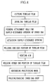
- an envelope type inner bag for the transport tank of the present invention includes a synthetic-resin multilayer tubular film constituted of outer and inner tubular films, a synthetic-resin reinforcing film to be put on both ends of the multilayer tubular film, a welding line formed by welding both ends of the multilayer tubular film together with the reinforcing film, and an inner bag supply-discharge opening to be fitted in a supply-discharge opening disposed in a lower portion of the transport tank.
- the multilayer tubular film is at least doubled with two layers including the inner and outer tubular films.
- An envelope type inner bag is completed after sealing the ends of the multilayer tubular film by the welding line.
- a hole to attach the inner bag supply-discharge opening is formed in the multilayer tubular film.
- the inner bag supply-discharge opening is welded to a peripheral edge of the hole before forming the welding line.
- a tubular film is inserted into another one after cutting these films from a synthetic-resin tubular film to form a multilayer tubular film having at least two layers.
- a welding line is formed in a width direction by welding to seal one end of the multilayer tubular film in a bag shape.
- both ends of the welding line are reinforced by putting the reinforcing film thereon.
- a hole penetrating inside the multilayer tubular film is formed on one surface of the multilayer tubular film, and then an inner bag supply-discharge opening is welded to the hole.
- the welding line is formed in a width direction with welding to seal an other end of the multilayer tubular film attached with the inner bag supply-discharge opening in a bag shape.
- the welding line is reinforced by putting a reinforcing film on corner portions at both ends thereof in forming the welding line.
- the reinforcing film is folded and disposed to sandwich a position constituted only of the outer tubular film at both ends of the welding line. Both ends of the welding line have a linear first welding line portion or a circular-arc second welding line portion which turn inward of the multilayer tubular film.
- length of the multilayer tubular film is IL
- width thereof is IW
- an inner peripheral length of the transport tank in a longitudinal cross-sectional surface in a longitudinal direction is TLt
- the inner peripheral length of the transport tank in the longitudinal cross-sectional surface in a width direction is TLr
- the reinforcing film is formed by folding the corner portions at both the ends of the multilayer tubular film.
- the inner bag is formed to be an envelope shape, it is unnecessary to form an approximately tubular inner bag body having approximately the same shape as the transport tank.
- the reinforcing film is put on both ends of the multilayer tubular film, and then the welding line is formed by sealing both ends. Since the corner portions of the inner bag are reinforced by the reinforcing film, if the corner portions are rubbed against the inside of the transport tank, the durability of the inner bag body does not go down.
- the thickness in the welding line is uniformed by welding the reinforcing film together with the corner portion constituted only of the outer tubular film, so that the two-layered portion disappears. Accordingly, since approximately uniform heat energy is applied to the corner portion in the welding, the damage of the welding line caused by the application of the excessive heat energy is eliminated, maintaining the strength of the welding line in uniform. Namely, when the tubular film is multilayered, a gap between the outer tubular film and the inner tubular film is there at both side edges of the multilayer tubular film.
- the portion where only the outer tubular film resides is a two layer
- the portion where the outer and inner tubular films overlaidly reside is a four layer. Therefore, the difference in thickness in the welding line occurs between the two-layered portion and the four-layered portion. Since the welding energy is uniformly applied to the entire corner portion of the multilayer tubular film, the excessive welding energy is applied to the two-layered portion to damage there, so that the two-layered portion may not be able to endure the impact during transportation. To make matters worse, since the thickness of the two-layered portion becomes thinner by the application of the welding energy, the sealing property and the strength in the two-layered portion are insufficient, so that the two-layered portion is easily tore. Meanwhile, in the present invention, since the corner portions of the inner bag are welded after putting the reinforcing film thereon such that the entire welding line has uniform thickness, so that the sealing property and the strength of the corner portions are ensured.
- both end portions of the welding line are formed as an oblique line or a circular-arc line which turns inward of the tubular film, so that the protrusion of the corner portions at both ends caused by the internal liquid pressure becomes small in scale. Moreover, since the force to a weaker sealing portion in the welding line becomes reduced, the sealing property, the strength and the durability of the corner portion are ensured all the more.
- a twenty-foot ISO container 10 is constituted of a tank body 11 and a frame 12 for holding the tank body 11.
- a hatch 13 is formed at the top face of the tank body 11. The maintenance and filling of liquid are performed through the hatch 13.
- a lid 14 is locked by a locking member in order to prevent the lid 14 covering the hatch 13 from opening.
- a tank supply-discharge opening 15 is formed in one end of a lower part of the tank body 11.
- a foot valve 16 is fixed through a flange 15a of the tank supply-discharge opening 15.
- An inner bag for a transport tank (hereinafter referred to as an inner bag) 20 is set into the tank body 11.
- the inner bag 20 is brought into the tank body 11 from the hatch 13 by an operating person to load in the tank body 11.
- the inner bag 20 upswells in the tank body 11 by pouring the liquid as cargo therein from the tank supply-discharge opening 15 through the foot valve 16, so that the inner bag 20 operates as a lining to the tank body 11.
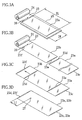
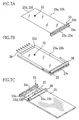
- the inner bag 20 is constituted of an inner bag body 21 having an envelope shape and an inner bag supply-discharge opening 22 to be fitted in the tank supply-discharge opening 15. Since the inner bag 20 is formed to the envelope shape, the inner bag body 21 can be easily formed as shown in FIGS.3A - 3D.
- a tubular film 23 is cut into a predetermined length after being drawn from a film roll 24 which is the roll of the tubular film 23, and then end portions 23c - 23f of the two tubular films 23a and 23b are closed by thermally welding or the like (see FIGS. 7A and 7C).
- a longitudinal cross-sectional surface including a central line CL1 extending in the longitudinal direction of the tank body 11 (B-B arrowed cross-sectional surface) is referred to as a longitudinal cross-sectional surface in the longitudinal direction
- a longitudinal cross-sectional surface including a central line CL2 extending in the width direction of the tank body 11 (C-C arrowed cross-sectional surface shown by the arrow) is referred to as a longitudinal cross-sectional surface in the width direction.
- a line CL3 shown in FIG. 2B is a central line extending in a height direction of the tank body 11.
- the tank body 11 is formed to a tubular shape whose both ends are closed to be placed transversally, while the inner bag 20 is formed to the envelope shape. Therefore, if the inner bag 20 is smaller than the appropriate size corresponding to the size of the tank body 11, a predetermined filling capacity is not ensured. To make matters worse, the smaller inner bag creates a gap between the inner peripheral surface of the tank body 11 and the inner bag 20 where the inner bag 20 together with the liquid can move to damage the welded portion of the inner bag supply-discharge opening 22 and the welding lines of the both ends of the inner bag 20. Whereas, if the inner bag 20 is larger than the appropriate size corresponding to the size of the tank body 11, the raw material of the inner bag 20 is wasted.
- the size of the envelope type inner bag 20 is limited within a specific range based on the size of the tank body 11 for the purpose of preventing the filling failure and the damage of the inner bag 20.
- the length of the inner bag 20 is IL
- the width thereof is IW
- the inner peripheral length (first inner peripheral length) of the tank body 11 in the longitudinal cross-sectional surface in the longitudinal direction is TLt
- the inner peripheral length (second inner peripheral length) of the tank body 11 in the longitudinal cross-sectional surface in the width direction is TLr
- the following conditions are satisfied: 0.47 ⁇ TLt ⁇ IL ⁇ 0.6 ⁇ TLt ; and 0.47 ⁇ TLr ⁇ IW ⁇ 0.6 ⁇ TLr .
- IL and IW preferably satisfy the following conditions: 0.49 ⁇ TLt ⁇ IL ⁇ 0.55 ⁇ TLt ; and 0.47 ⁇ TLr ⁇ IW ⁇ 0.6 ⁇ TLr .
- the size of the inner bag 20 is limited based on the inner peripheral length of the tank body 11, so that the tank body 11 may have different shapes than tube such as an elliptical shape or others.
- the distance L1 is limited within a range 0.44 ⁇ IW ⁇ L1 ⁇ 0.50 ⁇ IW based on the width IW of the inner bag 20, so that it is possible to position the central positions in the longitudinal direction of the tank body 11 and the inner bag 20 with each other if the inner bag 20 is attached to the tank body 11 with reference to the tank supply-discharge opening 15, which is formed in the end of the lower part of the tank body 11.
- the extra portions in the both ends of the inner bag 20 can be distributed approximately evenly in the tank body 11. Accordingly, the extra portion of the inner bag 20 does not build up on one side to be sandwiched between the tank body 11 and the inner bag body 21, so that the filling failure and the damage of the inner bag 20 are eliminated.
- the tubular film 23 is drawn from the film roll 24 to be put on a work table 25, and then cut into the length IL by a cutter 26 or the like.
- the tubular film 23 is made from LLDPE (linear low density polyethylene), and wound into a roll shape to be stored. Since the inner bag 20 is doubled in the present embodiment, it is necessary to form the two tubular films 23a and 23b by cutting the tubular film 23 twice into the length IL.
- the thickness of a single layer of the tubular film 23 is 120 ⁇ m. Since the tubular film 23 of the present embodiment has two layers, the entire thickness of the tubular film 23 is 240 ⁇ m.
- the thickness of the film is preferably 80 - 500 ⁇ m, especially 100 - 300 ⁇ m.
- one tubular film 23a is inserted into another tubular film 23b.
- a hole 27 corresponding to the inner bag supply-discharge opening 22 is opened on only the upper two layers of films by a punch or a cutter.
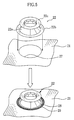
- the inner bag supply-discharge opening 22 is constituted of a supply-discharge mouth 22a having a truncated conical and cylindrical shape, a welding flange 22b and an attachment flange 22c which are attached to both the ends of the supply-discharge mouth 22a, and integrally formed by using LLDPE for example.
- the welding flange 22b and the inner bag body 21 are thermally welded by a thermal welding apparatus (not shown) to form welding lines 28 and 29. As shown in FIG.
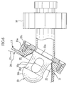
- a flange 30a of an inner bag suction preventing member 30 and the foot valve 16 are attached to the flange 15a of the tank supply-discharge opening 15, so that the inner bag supply-discharge opening 22 is attached firmly to the tank supply-discharge opening 15.
- the supply-discharge mouth 22a is formed along the inner peripheral surface of the tank supply-discharge opening 15.
- the thermal welding apparatus 33 is constituted of a receiving stage 33a and a welding head 33b. The heat is applied to the end portions 23c and 23e, which are held by the welding head 33b and the receiving stage 33a after the welding head 33b has been moved down.
- thermal welding lines 35a and 35b of 5 mm in width are formed linearly at an interval of 5-10mm.
- one or three or more thermal welding lines may be formed.
- a corrugated thermal welding line may be applied to the present embodiment instead of the linear one. If the plural thermal welding lines are formed, all lines may be formed together, or each line may be formed one by one.
- a thermal welding line 36a is formed by welding the end portion 23e of the inner tubular film 23b, and then a thermal welding line 36b is formed by welding the end portions 23c and 23e of the outer and inner tubular films 23a and 23b into four layer at the outer side of the welding line 36a.
- thermal welding line 36b is positioned outside the thermal welding line 36a.
- thermal welding lines 37a and 37b are formed by welding the end portions 23c and 23e of the tubular films 23a and 23b into two layer separately wherein the inner tubular film 23a is slightly shorter in length than the outer tubular film 23b.
- the thermal welding line may be welded at a time, if the length of the welding head 33b is limited, the thermal welding line may be welded sequentially every length of the welding head 33b.
- the end portions of the tubular film 23 may be sealed by ultrasonic welding, other welding method or an adhesive agent, instead of the thermal welding by using the heat-sealing type thermal welding apparatus 33.
- the welding and the adhesion may be used together.
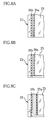
- the thermal welding lines 36a, 37a and 37b are formed on the single tubular films 23a and 23b, and have approximately uniformed thickness. Meanwhile, the thermal welding lines 35a, 35b and 36b are formed on the doubled tubular films 23a and 23b. Therefore, as shown in FIG. 9A, a two-layered portion (A1) including only the outer tubular film 23a without a reinforcing film 50 and a four-layered portion (A2) constituted of the outer and inner tubular films 23a and 23b are produced. Since the excessive welding energy is applied to the section A1 upon thermal welding, the welded part is damaged to lower the impact resistance in transporting.
- the section A1 is thermally welded so as to have a four-layered structure by putting thereon the reinforcing film 50 of the same material and thickness as the tubular film 23.
- the thickness of the thermal welding lines 35a and 35b in the section A3 becomes approximately uniform. Consequently, the excessive heat energy is not applied partially, so that the sealing property, the strength and the impact resistance in the section A3 are not lowered.
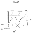
- FIG.10 There is another method of reinforcing the corner portion of the inner bag body.
- front and rear side portions of a reinforcing film 51 are folded diagonally along a folding line 52 to be thermally welded.
- the thickness of the reinforcing film 51 becomes twice, so that it is possible to reinforce the corner portion of the outer tubular film 23a.
- the front and rear side portions of the reinforcing film 51 may be folded along a folding line 53 parallel to the side edge of the outer tubular film 23a.
- the reinforcing film 51 may be thicker than the tubular film 23.
- a pressing roller 38 is rotated on the work table 25 from the welded one end portion 23c toward the other end portion 23d to vent air 39 in the doubled inner bag body 21.
- the air39 may be vented by folding the inner bag body 21 from one end side to the other end side. Since the inner bag supply-discharge opening 22 is attached close to the other end portion 23d so as to protrude from the inner bag body 21, the air between the inner bag supply-discharge opening 22 and the other end portion 23d is vented by using a small roller for avoiding the supply-discharge opening 22.
- the other end portions 23d and 23f of tubular films 23a and 23b, in which the air has been vented, are welded by the thermal welding apparatus 33 in the same way as the one end portions 23c and 23e.
- the inner bag 20 shown in FIG.11A is completed.
- a positioning mark 45 is recorded along a central line extending in the longitudinal direction of the inner bag 20 by using an oil-based ink or the like.
- the inner bag body 21 is folded, and then contained in a packaging bag 40 as shown in FIG.11E.
- the positioning mark 45 is formed linearly in the present embodiment, the shape or size of the positioning mark is not limited especially.
- the inner bag body 21 with the supply-discharge opening 22 directed downward is folded inward along inward folding lines 21e in parallel with the positioning mark 45 so as to make both the side edge portions 21a and 21b approach the central line.
- the inward-folded portions are folded inward again along inward folding lines 21f in parallel with the central line extending in the longitudinal direction so as to make the inward folding line 21e approach the central line.
- the inner bag body 21 is double folded.
- the inner bag body 21 is folded plural times along the inward folding lines 21g toward the inner bag supply-discharge opening 22 from both the end portions 21c and 21d of the inner bag body 21, so that the inner bag body 21 is folded into a small size as shown in FIG.11D.
- the inner bag body 21 may be rewound from the one end to be a roll shape instead of being folded inward along the inward folding lines 21g.
- the inner bag 20 is put in the packaging bag 40 as shown in FIG. 11E. Since the inner bag body 21 is double folded along the inward folding lines 21e and 21f, it can be contained compactly. Note that the inner bag body 21 may be folded once or three times above along the central line extending in the longitudinal direction.
- the inner bag body 21 is folded such that the inner bag supply-discharge opening 22 is directed outside the inner bag body 21, the inner bag supply-discharge opening 22 can be inserted to the tank supply-discharge opening 15 easily.
- the inner bag body 21 is folded inward along the inward folding lines 21g, so that the inner bag body 21 can be expanded easily in the longitudinal direction of the tank body 11 in a state that the inner bag supply-discharge opening 22 is set in the tank supply-discharge opening 15.
- the inner bag body 21 is folded inward along each of the inward folding lines 21e and 21f in a state that the inner bag supply-discharge opening 22 is directed downward, the inner bag body 21 is expanded by itself by filling the liquid from the inner bag supply-discharge opening 22.
- the inner bag 20 contained in the packaging bag 40 is brought into the tank body 11 by the operating person to be taken out of the packaging bag 40.
- the positioning mark 45 is recorded linearly on the inner bag 20 so as to correspond to the central liner CL1 extending in the longitudinal direction of the tank body 11.
- the inner bag supply-discharge opening 22 is inserted in the tank supply-discharge opening 15 so as to conform the positioning mark 45 to the central line CL1.
- the attachment flange 22c is attached firmly to the flange 15a.
- the inner bag body 21 folded along the inward folding lines 21g is unfolded in the longitudinal direction of the tank body 11, and then the folded portions along the inward folding line 21f are unfolded. Both the side edge portions which are folded along the inward folding lines 21e are not unfolded. Since the approximately overall width of the inside of the tank body 11 is covered by the inner bag body 21 of which the both side edge parts are folded along the inward folding lines 21e, even if the both side edge portions are unfolded, they are folded again by their weight. After unfolding the inner bag body 21 except for both the side edge portions, the inner bag suction preventing member 30 and the foot valve 16 are attached to the tank supply-discharge opening 15 from the outside of the tank body 11 as shown in FIG.6.
- the liquid as the cargo is filled from the tank supply-discharge opening 15.
- the filling speed is 50 liters per minute, for example.
- the inner bag body 21 is extended in the longitudinal direction in the tank body 11, so that the inner bag body 21 upswells by filling the liquid in the inner bag body 21 smoothly.
- the both side edge portions of the inner bag body 21, which are folded inward, are gradually unfolded with the filling of the liquid, so that the end portions of the inner bag body 21 are not accidentally caught between the inner bag body 21 and the tank body 11 by the weight of the portion in which the liquid is filled. Therefore, the inner bag body 21 upswells smoothly by the filling of the liquid.
- About 20 tons of liquid is contained in the inner bag body 21.
- the thickness of the thermal welding lines 35a and 35b within the section A3 of the inner bag body 21 is approximately uniformed by using the reinforcing film 50. Therefore, approximately uniform welding energy is applied to the section A3 in the thermal welding, the welding line in the thinner part is not damaged by the application of the excessive heat energy. Accordingly, the strength and the durability of the welding line portion are maintained.
- a welding line portion (A4) is constituted only of the reinforcing film 50 to be two-layered and the thickness thereof is thinner than the section A3.
- the sealing property, the strength and the durability of the inner bag body 21 are not influenced.
- the thickness of the section A4 is approximately uniform, the approximately uniform strength is obtained, so that the sealing property, the strength and the durability in the section A4 are not lowered.
- the inner bag body 21 is loaded in the tank body 11 to extend in the longitudinal direction, and its side edge portions are folded inward toward the central line extending in the width direction of it. That prevents the air from entering the inner bag body 21 and the inner bag body 21 can be used for the anaerobic liquid.
- the inner bag body 21 and the inner bag supply-discharge opening 22 are made from LLDPE having high chemical resistance, the tank body 11 has more choices in material. Furthermore, it is unnecessary to line the inner peripheral surface of the tank body 11 with fluorocarbon resin such as polytetrafluoroethylene.
- the inner bag body 21 When the inner bag body 21 dwindles to close with the inner bag supply-discharge opening 22 after the remaining amount of the liquid is reduced, the inner bag body 21 may be accidentally sucked into the inner bag supply-discharge opening 22 to cover the opening 22.
- the inner bag suction preventing member 30 In order to prevent the inner bag body 21 from covering the inner bag supply-discharge opening 22 in discharging the liquid from the tank supply-discharge opening 15, when the liquid is discharged from the tank supply-discharge opening 15, a passage between the inner bag body 21 and the inner bag supply-discharge opening 22 is ensured by the inner bag suction preventing member 30.
- the inner bag suction preventing member 30 is integrally constituted of a semi-spherical end 30b arranged to protrude toward the inside of the tank body 11, a tubular portion 30d whose peripheral surface has plural continuous holes 30c, and an attachment flange 30a provided on the base part of the tubular portion 30d.
- the semi-spherical end 30b protrudes toward the inside of the inner bag body 21, so that the residual liquid in the inner bag body 21 can be surely discharged through the continuous holes 30c without the inner bag body 21 stick to the inner bag supply-discharge opening 22.
- an air vent cap and an air vent valve may be welded to the inner bag body 21 at a position corresponding to the hatch 13. In this case, if the air enters the inner bag body 21 by the operation of loading the inner bag body 21 or filling the liquid, the air can be vented in easily.
- the inner bag body 21 is made from LLDPE, it may be made from LDPE (low-density polyethylene), OP (biaxially oriented polypropylene) and other synthetic resin.
- LLDPE low-density polyethylene
- OP biaxially oriented polypropylene
- the inner bag body 21 is doubled in the present embodiment, it may have three ore more layers.
- cylindrical tank body 11 may be formed to have an elliptical shape or others.
- the inner bag 20 may be used not only for the tank container, but also for a tanker lorry and so forth.
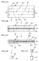
- both end portions of thermal welding lines 61 and 62 have oblique welding line portions 63 and 64 which turn inward of the inner bag body 60.
- both end portions of thermal welding lines 66 and 67 of an inner bag body 65 shown in FIG.13 have circular-arc welding line portions 68 and 69 instead of the oblique welding line portions 63 and 64.
- the inclination angle ⁇ of the welding line portions 63 and 64 to both side edges 60a of the inner bag body 60 is an obtuse angle, while the welding line portions 68 and 69 contact with both side edges 65a of the inner bag body 65 in a circular arc manner.
- an ear portion which is an outside portion of the welding line, contacts with the inner surface of the tank body 11, so that it is possible to prevent the welding line portion in the corner portions at both ends from rubbing directly against the material of the inside of the tank body 11. Furthermore, since the force to the weaker sealing portion on the welding line is reduced, the sealing property, the strength and the durability in the corner portion are enhanced.
- a welding head having a head contact part with the same shape as these welding line portions is used. Note that a welding line portion with a polygonal shape may be used instead of the oblique welding line portions 63 and 64.
- the reinforcement by both the shape of the thermal welding line and the reinforcing film makes it possible to obtain higher reinforcing effect, it is possible to obtain the reinforcing effect only with the reinforcement by the shape of the thermal welding line, so that the reinforcing film may be omitted.
- the thermal welding lines 63, 64, 68 and 69 it is preferable to put the reinforcing film 50 shown in FIG. 9 on the two-layered portion constituted only of the outer tubular film 23a so as to uniform the thickness of the welding line portion. In this case, the sealing property and the strength of the corner portions of the inner bag bodies 60 and 65 can be enhanced further.
- Each main portion of the thermal welding lines shown in FIGS.8, 12 and 13 may not be formed linearly, but formed in a circular-arc shape expanding outwardly.
- thermal welding lines 72 and 73 are formed by thermally welding a corner portion 70a with it folded along a folding line 71 at both ends of an inner bag body 70.
- the corner portions 70a at both ends become thicker by being folded, so that the corner portion 70a is reinforced like the above embodiment.
- thermal welding lines 77 and 78 are formed by thermally welding a portion 75a with it folded along a folding line 76 at both ends of an inner bag body 75.
- the whole thermal welding lines 77 and 78 become thicker to reinforce themselves. Thereby, even if the reinforcing film other than the inner bag body is not used, the corner portions at both ends of the inner bag bodies 70 and 75 can be reinforced by using a portion of these inner bag bodies 70 and 75.
- the attachment hole may be formed in the inner bag body to be attached to the tank supply-discharge opening after welding the one end portion of the tubular film.
Landscapes
- Engineering & Computer Science (AREA)
- Mechanical Engineering (AREA)
- Making Paper Articles (AREA)
- Bag Frames (AREA)
Claims (14)
- Innenbeutel (20) für einen Transporttank, der auf entnehmbare Weise in den Transporttank zu geben ist, umfassend:- einen mehrlagigen, röhrenförmigen Kunstharzfilm (23), der durch einen äußeren röhrenförmigen Film (23a) und einen inneren röhrenförmigen Film (23b), der in den äußeren röhrenförmigen Film einzufügen ist, gebildet ist, und der zumindest mit dem äußeren und dem inneren röhrenförmigen Film gedoppelt ist;- einen Kunstharzverstärkungsfilm (50, 51), der auf Eckabschnitte an beiden Enden des mehrlagigen, röhrenförmigen Films zu geben ist;- eine Schweißlinie (35a, 35b), die durch Schweißen beider Enden des mehrlagigen, röhrenförmigen Films mit dem Verstärkungsfilm gebildet ist, um beide Enden zum Bilden des mehrlagigen, röhrenförmigen Films zu einer umschlagartigen Beutelform abzudichten; und- eine Innenbeutel-Zufuhr-Ausstoßöffnung (22), die in eine Zufuhr-Ausstoßöffnung (15) einzusetzen ist, die in einem unteren Abschnitt des Transporttanks vorgesehen ist, wobei die Innenbeutel-Zufuhr-Ausstoßöffnung an einem Umfangsrand eines Lochs (27) geschweißt ist, das in dem mehrlagigen, röhrenförmigen Film gebildet ist, bevor die Schweißlinie gebildet wird.
- Innenbeutel nach Anspruch 1, bei welchem der Verstärkungsfilm derart gefaltet und vorgesehen ist, um einen Abschnitt sandwichartig aufzunehmen, der nur durch den äußeren, röhrenförmigen Film gebildet ist und zwar an beiden Enden der Schweißlinie.
- Innenbeutel nach Anspruch 2, bei welchem die beiden Enden der Schweißlinie (61, 62) einen geradlinigen ersten Schweißlinienabschnitt (63, 64) besitzen, der sich nach innerhalb des mehrlagigen, röhrenförmigen Films wendet.
- Innenbeutel nach Anspruch 2, bei welchem die beiden Enden der Schweißlinie (66, 67) einen kreisbogenförmigen, zweiten Schweißlinienabschnitt (68, 69) besitzen, der sich nach innerhalb des mehrlagigen, röhrenförmigen Films wendet.
- Innenbeutel nach Anspruch 1, bei welchem die beiden Enden der Schweißlinie (61, 62) einen geradlinigen, ersten Schweißlinienabschnitt (63, 64) besitzen, der sich nach innerhalb des mehrlagigen, röhrenförmigen Films wendet.
- Innenbeutel nach Anspruch 1, bei welchem beide Enden der Schweißlinie (66, 67) einen kreisbogenförmigen, zweiten Schweißlinienabschnitt (68, 69) besitzen, der sich nach innerhalb des mehrlagigen, röhrenförmigen Films wendet.
- Innenbeutel nach Anspruch 1, bei welchem eine Länge des mehrlagigen, röhrenförmigen Films IL ist, eine Breite hiervon ist IW, eine innere Umfangslänge des Transporttanks in einer Längsquerschnittsfläche in einer Längsrichtung ist TLt, und die innere Umfangslänge des Transporttanks in der Längsquerschnittsfläche in einer Breitenrichtung ist TLr, wobei die folgenden Bedingungen erfüllt sind:


- Innenbeutel nach Anspruch 1, bei welchem der Verstärkungsfilm durch Falten der Eckabschnitte an beiden Enden des mehrlagigen, röhrenförmigen Films gebildet ist.
- Herstellverfahren für einen Innenbeutel (20) vom Umschlagtyp für einen Transporttank, der in den Transporttank auf entnehmbare Weise zu geben ist, umfassend:einen Mehrlagenbildungsschritt zum Bilden eines mehrlagigen, röhrenförmigen Films (23), der mindestens zwei Lagen besitzt, durch Einfügen eines röhrenförmigen Films in einen anderen röhrenförmigen Film, nachdem ein röhrenförmiger Kunstharzfilm zum Bilden der röhrenförmigen Filme geschnitten wurde;einen ersten Abdichtschritt mittels Schweißens zum Abdichten eines Endes des mehrlagigen, röhrenförmigen Films zu einer Beutelform durch Bilden einer Schweißlinie (35a, 35b) in einer Breitenrichtung, wobei die Schweißlinie durch Geben eines Verstärkungsfilms (50) an Eckabschnitten an beiden Enden hiervon beim Bilden der Schweißlinie verstärkt wird;einen Schweißschritt des Schweißens einer Innenbeutel-Zufuhr-Ausstoßöffnung (22) an einem Umfangsrand eines Lochs (27), das an einer Oberfläche des mehrlagigen, röhrenförmigen Films gebildet ist, wobei das Loch nach innerhalb des mehrlagigen, röhrenförmigen Films eindringt; undeinen zweiten Abdichtschritt mittels Schweißens zum Abdichten eines anderen Endes des mehrlagigen, röhrenförmigen Films, an welchem die zweite Zufuhr-Ausstoßöffnung eingebracht ist, zu einer Beutelform durch Bilden einer Schweißlinie in einer Breitenrichtung, wobei die Schweißlinie durch Geben eines Verstärkungsfilms an Eckabschnitten an beiden Enden hiervon beim Bilden der Schweißlinie verstärkt wird.
- Herstellverfahren nach Anspruch 9, bei welchem der Verstärkungsfilm derart gefaltet und vorgesehen wird, um einen Abschnitt sandwichartig aufzunehmen, der nur durch den äußeren röhrenförmigen Film gebildet ist, und zwar an beiden Enden der Schweißlinie, wobei die Schweißlinie in diesem Zustand gebildet wird.
- Herstellverfahren nach Anspruch 9, bei welchem die beiden Enden der Schweißlinie nach innerhalb des mehrlagigen, röhrenförmigen Films gewendet werden.
- Herstellverfahren nach Anspruch 9, bei welchem die beiden Enden der Schweißlinie ein kreisförmiger Bogen sind.
- Herstellverfahren nach Anspruch 9, ferner umfassend:einen Luftbelüftungsschritt zum Belüften von Luft (39) von dem anderen Ende des mehrlagigen, röhrenförmigen Films, von welchem das eine Ende in dem ersten Abdichtschritt abgedichtet ist, wobei der Luftbelüftungsschritt vor dem zweiten Abdichtschritt ausgeführt wird.
- Herstellverfahren nach Anspruch 9, bei welchem die innere Umfangslänge des Transporttanks in einer Längsquerschnittsfläche in einer Längsrichtung TLt ist, und die innere Umfangslänge des Transporttanks in der Längsquerschnittsfläche in einer Breitenrichtung ist TLr, wobei die Schneidlänge IL des röhrenförmigen Films und die Breit IW hiervon in dem Dopplungsschritt die folgenden Bedingungen erfüllen:


Applications Claiming Priority (4)
| Application Number | Priority Date | Filing Date | Title |
|---|---|---|---|
| JP2004014697 | 2004-01-22 | ||
| JP2004014697 | 2004-01-22 | ||
| JP2004064595A JP4474180B2 (ja) | 2004-01-22 | 2004-03-08 | 輸送タンク用内袋及びその製造方法 |
| JP2004064595 | 2004-03-08 |
Publications (2)
| Publication Number | Publication Date |
|---|---|
| EP1557377A1 EP1557377A1 (de) | 2005-07-27 |
| EP1557377B1 true EP1557377B1 (de) | 2007-08-29 |
Family
ID=34635690
Family Applications (1)
| Application Number | Title | Priority Date | Filing Date |
|---|---|---|---|
| EP05001199A Expired - Lifetime EP1557377B1 (de) | 2004-01-22 | 2005-01-21 | Innenbeutel für einen Tankbehälter und dessen Herstellungsverfahren |
Country Status (4)
| Country | Link |
|---|---|
| US (1) | US7275869B2 (de) |
| EP (1) | EP1557377B1 (de) |
| JP (1) | JP4474180B2 (de) |
| DE (1) | DE602005002148T2 (de) |
Families Citing this family (4)
| Publication number | Priority date | Publication date | Assignee | Title |
|---|---|---|---|---|
| US20110164836A1 (en) * | 2010-01-05 | 2011-07-07 | Chen Yi-Min | Plastic bag with reinforced sides |
| JP6713311B2 (ja) * | 2016-03-28 | 2020-06-24 | 日新産商株式会社 | 内装袋の装着方法及び取り外し方法並びにその方法に用いる内装袋 |
| NL2018765B1 (en) * | 2017-04-24 | 2018-11-05 | Green Eye Capital B V | Assembly of an inliner and a tank container |
| US10807794B2 (en) * | 2018-02-05 | 2020-10-20 | Composite Containers, Llc | Liner for tank container |
Family Cites Families (13)
| Publication number | Priority date | Publication date | Assignee | Title |
|---|---|---|---|---|
| US3768724A (en) * | 1971-12-20 | 1973-10-30 | W Hill | Cushioned shipping bag |
| US3956045A (en) * | 1971-12-21 | 1976-05-11 | Hoffman Louis S | Method and apparatus for bonding layers of resinous material |
| US3949113A (en) * | 1971-12-27 | 1976-04-06 | Phillips Petroleum Company | Liner for reservoir of layered liquids |
| FR2207068B1 (de) | 1972-11-20 | 1978-02-03 | Vidilles Jacques | |
| JPS6115029Y2 (de) | 1980-09-02 | 1986-05-10 | ||
| JPS6148190U (ja) | 1984-09-04 | 1986-03-31 | 東急車輌製造株式会社 | コンテナ |
| JPS61104983A (ja) | 1984-10-26 | 1986-05-23 | 与那原 好宏 | 液体輸送容器 |
| US4658433A (en) * | 1985-09-11 | 1987-04-14 | First Brands Corporation | Rib and groove closure bag with bead sealed sides |
| US5066290A (en) * | 1986-02-07 | 1991-11-19 | Baxter International Inc. | Sterilizable multi-layer plastic materials for medical containers and the like |
| DE20121803U1 (de) * | 2000-03-22 | 2003-06-26 | K-Tank Supply Ltd., Kowloon, Hongkong | Flexibler Tank |
| JP2001354292A (ja) | 2000-06-13 | 2001-12-25 | Kyoritsu Butsuryu System:Kk | 液体コンテナ用の内袋 |
| US6626312B2 (en) * | 2000-06-28 | 2003-09-30 | Javier Urzua Maturana | Storage bag |
| GB2366283A (en) * | 2000-08-30 | 2002-03-06 | Brendan Mckenna | Apparatus for use in the transportation of liquids, gels, thixotropic fluids and the like |
-
2004
- 2004-03-08 JP JP2004064595A patent/JP4474180B2/ja not_active Expired - Lifetime
-
2005
- 2005-01-21 US US11/038,145 patent/US7275869B2/en not_active Expired - Lifetime
- 2005-01-21 EP EP05001199A patent/EP1557377B1/de not_active Expired - Lifetime
- 2005-01-21 DE DE602005002148T patent/DE602005002148T2/de not_active Expired - Lifetime
Also Published As
| Publication number | Publication date |
|---|---|
| JP2005231727A (ja) | 2005-09-02 |
| DE602005002148D1 (de) | 2007-10-11 |
| US20050181922A1 (en) | 2005-08-18 |
| JP4474180B2 (ja) | 2010-06-02 |
| US7275869B2 (en) | 2007-10-02 |
| DE602005002148T2 (de) | 2008-05-29 |
| EP1557377A1 (de) | 2005-07-27 |
Similar Documents
| Publication | Publication Date | Title |
|---|---|---|
| EP2149508B1 (de) | Transport- und Aufbewahrungsbehälter | |
| US5851072A (en) | Spout construction for bulk box liquid liner | |
| KR950011762B1 (ko) | 유연성 용기용 라이너 | |
| US7086429B2 (en) | Inner bag for transport tank and loading method thereof | |
| NZ208015A (en) | Inflatable dunnage bag,tapered or of triangular shape | |
| EP1557377B1 (de) | Innenbeutel für einen Tankbehälter und dessen Herstellungsverfahren | |
| US20100189528A1 (en) | Dunnage bag with double seal reusable inflation valve | |
| KR20100119504A (ko) | 유체용 용기 | |
| EP1568622A1 (de) | Transporttank und Verfahren zum Transportieren einer Fracht | |
| US7490990B2 (en) | Inner bag for transport tank | |
| JP2018115032A (ja) | フォイル裏打ちfibc(バルクバッグ)用のハーメチックシール | |
| EP1940701A1 (de) | Behälter für ein fluid | |
| EP2456681A2 (de) | Versiegelbare behälterverkleidungen und versiegelbare behälter | |
| JP2005239267A (ja) | 輸送タンク内袋の製造方法 | |
| JP2005239263A (ja) | 輸送タンク用内袋及びその製造方法 | |
| US10807794B2 (en) | Liner for tank container | |
| CA2464129C (en) | Self-venting ink cartridge | |
| WO2006123698A1 (ja) | タンクコンテナ用内袋、タンクコンテナ用内袋の製造方法及びタンクコンテナ用内袋の装着方法 | |
| JP2005239264A (ja) | 輸送タンク用内袋及びその製造方法 | |
| AU2002347976A1 (en) | Self-venting ink cartridge | |
| KR20000022409A (ko) | 패키징 용기 및 그의 제조방법 | |
| CA2714701A1 (en) | Disposable liner for bulk materials |
Legal Events
| Date | Code | Title | Description |
|---|---|---|---|
| PUAI | Public reference made under article 153(3) epc to a published international application that has entered the european phase |
Free format text: ORIGINAL CODE: 0009012 |
|
| AK | Designated contracting states |
Kind code of ref document: A1 Designated state(s): AT BE BG CH CY CZ DE DK EE ES FI FR GB GR HU IE IS IT LI LT LU MC NL PL PT RO SE SI SK TR |
|
| AX | Request for extension of the european patent |
Extension state: AL BA HR LV MK YU |
|
| 17P | Request for examination filed |
Effective date: 20051007 |
|
| AKX | Designation fees paid |
Designated state(s): DE GB |
|
| RAP1 | Party data changed (applicant data changed or rights of an application transferred) |
Owner name: FUJIFILM CORPORATION |
|
| GRAP | Despatch of communication of intention to grant a patent |
Free format text: ORIGINAL CODE: EPIDOSNIGR1 |
|
| RTI1 | Title (correction) |
Free format text: INNER BAG FOR A TRANSPORT TANK AND PRODUCING METHOD THEREOF |
|
| GRAS | Grant fee paid |
Free format text: ORIGINAL CODE: EPIDOSNIGR3 |
|
| GRAA | (expected) grant |
Free format text: ORIGINAL CODE: 0009210 |
|
| AK | Designated contracting states |
Kind code of ref document: B1 Designated state(s): DE GB |
|
| REG | Reference to a national code |
Ref country code: GB Ref legal event code: FG4D |
|
| REF | Corresponds to: |
Ref document number: 602005002148 Country of ref document: DE Date of ref document: 20071011 Kind code of ref document: P |
|
| PLBE | No opposition filed within time limit |
Free format text: ORIGINAL CODE: 0009261 |
|
| STAA | Information on the status of an ep patent application or granted ep patent |
Free format text: STATUS: NO OPPOSITION FILED WITHIN TIME LIMIT |
|
| 26N | No opposition filed |
Effective date: 20080530 |
|
| P01 | Opt-out of the competence of the unified patent court (upc) registered |
Effective date: 20230515 |
|
| PGFP | Annual fee paid to national office [announced via postgrant information from national office to epo] |
Ref country code: GB Payment date: 20231130 Year of fee payment: 20 |
|
| PGFP | Annual fee paid to national office [announced via postgrant information from national office to epo] |
Ref country code: DE Payment date: 20231128 Year of fee payment: 20 |
|
| REG | Reference to a national code |
Ref country code: DE Ref legal event code: R071 Ref document number: 602005002148 Country of ref document: DE |
|
| REG | Reference to a national code |
Ref country code: GB Ref legal event code: PE20 Expiry date: 20250120 |
|
| PG25 | Lapsed in a contracting state [announced via postgrant information from national office to epo] |
Ref country code: GB Free format text: LAPSE BECAUSE OF EXPIRATION OF PROTECTION Effective date: 20250120 |