EP1557364A1 - Verfahren und Vorrichtung zum Vereinzeln und Weitertransportieren von flexiblen, flächigen Erzeugnissen - Google Patents
Verfahren und Vorrichtung zum Vereinzeln und Weitertransportieren von flexiblen, flächigen Erzeugnissen Download PDFInfo
- Publication number
- EP1557364A1 EP1557364A1 EP05000665A EP05000665A EP1557364A1 EP 1557364 A1 EP1557364 A1 EP 1557364A1 EP 05000665 A EP05000665 A EP 05000665A EP 05000665 A EP05000665 A EP 05000665A EP 1557364 A1 EP1557364 A1 EP 1557364A1
- Authority
- EP
- European Patent Office
- Prior art keywords
- product
- products
- stack
- conveying element
- conveying
- Prior art date
- Legal status (The legal status is an assumption and is not a legal conclusion. Google has not performed a legal analysis and makes no representation as to the accuracy of the status listed.)
- Granted
Links
- 238000000034 method Methods 0.000 title claims abstract description 28
- 239000000853 adhesive Substances 0.000 claims description 47
- 230000001070 adhesive effect Effects 0.000 claims description 44
- 230000000977 initiatory effect Effects 0.000 claims description 43
- 238000000926 separation method Methods 0.000 claims description 25
- 238000012546 transfer Methods 0.000 claims description 24
- 210000000056 organ Anatomy 0.000 claims description 5
- 230000000087 stabilizing effect Effects 0.000 claims description 5
- 230000009467 reduction Effects 0.000 claims description 3
- 230000001939 inductive effect Effects 0.000 claims 1
- 230000002123 temporal effect Effects 0.000 claims 1
- 239000000047 product Substances 0.000 description 193
- 230000006641 stabilisation Effects 0.000 description 9
- 238000011105 stabilization Methods 0.000 description 9
- 239000003795 chemical substances by application Substances 0.000 description 8
- 230000000694 effects Effects 0.000 description 8
- 239000003381 stabilizer Substances 0.000 description 8
- 230000008569 process Effects 0.000 description 7
- 239000013589 supplement Substances 0.000 description 6
- 238000012545 processing Methods 0.000 description 5
- 238000013461 design Methods 0.000 description 3
- 238000012423 maintenance Methods 0.000 description 3
- 238000010008 shearing Methods 0.000 description 3
- 230000003068 static effect Effects 0.000 description 3
- 230000001154 acute effect Effects 0.000 description 2
- 230000002411 adverse Effects 0.000 description 2
- 230000008901 benefit Effects 0.000 description 2
- 238000010276 construction Methods 0.000 description 2
- 230000001419 dependent effect Effects 0.000 description 2
- 238000001514 detection method Methods 0.000 description 2
- 238000000605 extraction Methods 0.000 description 2
- 210000003734 kidney Anatomy 0.000 description 2
- 230000002093 peripheral effect Effects 0.000 description 2
- 230000001737 promoting effect Effects 0.000 description 2
- 230000009471 action Effects 0.000 description 1
- 238000004026 adhesive bonding Methods 0.000 description 1
- 239000012790 adhesive layer Substances 0.000 description 1
- 238000013459 approach Methods 0.000 description 1
- 238000005452 bending Methods 0.000 description 1
- 239000006227 byproduct Substances 0.000 description 1
- 230000015556 catabolic process Effects 0.000 description 1
- 239000011248 coating agent Substances 0.000 description 1
- 238000000576 coating method Methods 0.000 description 1
- 230000006735 deficit Effects 0.000 description 1
- 238000006731 degradation reaction Methods 0.000 description 1
- 238000010586 diagram Methods 0.000 description 1
- 238000007599 discharging Methods 0.000 description 1
- 238000006073 displacement reaction Methods 0.000 description 1
- 230000005489 elastic deformation Effects 0.000 description 1
- 230000001771 impaired effect Effects 0.000 description 1
- 239000013067 intermediate product Substances 0.000 description 1
- 238000002955 isolation Methods 0.000 description 1
- 238000010380 label transfer Methods 0.000 description 1
- 239000000463 material Substances 0.000 description 1
- 238000012986 modification Methods 0.000 description 1
- 230000004048 modification Effects 0.000 description 1
- 230000000717 retained effect Effects 0.000 description 1
- 230000001360 synchronised effect Effects 0.000 description 1
- 230000007704 transition Effects 0.000 description 1
- 238000013519 translation Methods 0.000 description 1
Images



Classifications
-
- B—PERFORMING OPERATIONS; TRANSPORTING
- B65—CONVEYING; PACKING; STORING; HANDLING THIN OR FILAMENTARY MATERIAL
- B65H—HANDLING THIN OR FILAMENTARY MATERIAL, e.g. SHEETS, WEBS, CABLES
- B65H3/00—Separating articles from piles
- B65H3/32—Separating articles from piles by elements, e.g. fingers, plates, rollers, inserted or traversed between articles to be separated and remainder of the pile
-
- B—PERFORMING OPERATIONS; TRANSPORTING
- B65—CONVEYING; PACKING; STORING; HANDLING THIN OR FILAMENTARY MATERIAL
- B65C—LABELLING OR TAGGING MACHINES, APPARATUS, OR PROCESSES
- B65C9/00—Details of labelling machines or apparatus
- B65C9/08—Label feeding
- B65C9/12—Removing separate labels from stacks
- B65C9/14—Removing separate labels from stacks by vacuum
-
- B—PERFORMING OPERATIONS; TRANSPORTING
- B65—CONVEYING; PACKING; STORING; HANDLING THIN OR FILAMENTARY MATERIAL
- B65H—HANDLING THIN OR FILAMENTARY MATERIAL, e.g. SHEETS, WEBS, CABLES
- B65H3/00—Separating articles from piles
- B65H3/08—Separating articles from piles using pneumatic force
- B65H3/0808—Suction grippers
-
- B—PERFORMING OPERATIONS; TRANSPORTING
- B65—CONVEYING; PACKING; STORING; HANDLING THIN OR FILAMENTARY MATERIAL
- B65H—HANDLING THIN OR FILAMENTARY MATERIAL, e.g. SHEETS, WEBS, CABLES
- B65H3/00—Separating articles from piles
- B65H3/42—Separating articles from piles by two or more separators mounted for movement with, or relative to, rotary or oscillating bodies
-
- B—PERFORMING OPERATIONS; TRANSPORTING
- B65—CONVEYING; PACKING; STORING; HANDLING THIN OR FILAMENTARY MATERIAL
- B65H—HANDLING THIN OR FILAMENTARY MATERIAL, e.g. SHEETS, WEBS, CABLES
- B65H2220/00—Function indicators
- B65H2220/09—Function indicators indicating that several of an entity are present
-
- B—PERFORMING OPERATIONS; TRANSPORTING
- B65—CONVEYING; PACKING; STORING; HANDLING THIN OR FILAMENTARY MATERIAL
- B65H—HANDLING THIN OR FILAMENTARY MATERIAL, e.g. SHEETS, WEBS, CABLES
- B65H2301/00—Handling processes for sheets or webs
- B65H2301/30—Orientation, displacement, position of the handled material
- B65H2301/33—Modifying, selecting, changing orientation
- B65H2301/332—Turning, overturning
- B65H2301/3321—Turning, overturning kinetic therefor
- B65H2301/33214—Turning, overturning kinetic therefor about an axis perpendicular to the direction of displacement and parallel to the surface of material
-
- B—PERFORMING OPERATIONS; TRANSPORTING
- B65—CONVEYING; PACKING; STORING; HANDLING THIN OR FILAMENTARY MATERIAL
- B65H—HANDLING THIN OR FILAMENTARY MATERIAL, e.g. SHEETS, WEBS, CABLES
- B65H2406/00—Means using fluid
- B65H2406/30—Suction means
- B65H2406/33—Rotary suction means, e.g. roller, cylinder or drum
- B65H2406/331—Rotary suction means, e.g. roller, cylinder or drum arranged for rotating while moving along material to be handled, e.g. rolling on material
- B65H2406/3312—Rotary suction means, e.g. roller, cylinder or drum arranged for rotating while moving along material to be handled, e.g. rolling on material arranged for planetary movement on rotary support means
-
- B—PERFORMING OPERATIONS; TRANSPORTING
- B65—CONVEYING; PACKING; STORING; HANDLING THIN OR FILAMENTARY MATERIAL
- B65H—HANDLING THIN OR FILAMENTARY MATERIAL, e.g. SHEETS, WEBS, CABLES
- B65H2406/00—Means using fluid
- B65H2406/30—Suction means
- B65H2406/36—Means for producing, distributing or controlling suction
- B65H2406/365—Means for producing, distributing or controlling suction selectively blowing or sucking
-
- Y—GENERAL TAGGING OF NEW TECHNOLOGICAL DEVELOPMENTS; GENERAL TAGGING OF CROSS-SECTIONAL TECHNOLOGIES SPANNING OVER SEVERAL SECTIONS OF THE IPC; TECHNICAL SUBJECTS COVERED BY FORMER USPC CROSS-REFERENCE ART COLLECTIONS [XRACs] AND DIGESTS
- Y10—TECHNICAL SUBJECTS COVERED BY FORMER USPC
- Y10T—TECHNICAL SUBJECTS COVERED BY FORMER US CLASSIFICATION
- Y10T156/00—Adhesive bonding and miscellaneous chemical manufacture
- Y10T156/17—Surface bonding means and/or assemblymeans with work feeding or handling means
- Y10T156/1702—For plural parts or plural areas of single part
- Y10T156/1744—Means bringing discrete articles into assembled relationship
- Y10T156/1768—Means simultaneously conveying plural articles from a single source and serially presenting them to an assembly station
- Y10T156/1771—Turret or rotary drum-type conveyor
- Y10T156/1773—For flexible sheets
-
- Y—GENERAL TAGGING OF NEW TECHNOLOGICAL DEVELOPMENTS; GENERAL TAGGING OF CROSS-SECTIONAL TECHNOLOGIES SPANNING OVER SEVERAL SECTIONS OF THE IPC; TECHNICAL SUBJECTS COVERED BY FORMER USPC CROSS-REFERENCE ART COLLECTIONS [XRACs] AND DIGESTS
- Y10—TECHNICAL SUBJECTS COVERED BY FORMER USPC
- Y10T—TECHNICAL SUBJECTS COVERED BY FORMER US CLASSIFICATION
- Y10T156/00—Adhesive bonding and miscellaneous chemical manufacture
- Y10T156/17—Surface bonding means and/or assemblymeans with work feeding or handling means
- Y10T156/1702—For plural parts or plural areas of single part
- Y10T156/1744—Means bringing discrete articles into assembled relationship
- Y10T156/1776—Means separating articles from bulk source
- Y10T156/1778—Stacked sheet source
- Y10T156/178—Rotary or pivoted picker
Definitions
- the invention relates to a method and an apparatus for separating and Further transport of flexible, flat products according to the preambles of independent claims.
- the prior art discloses various methods and devices for separating of labels and single sheets and their subsequent transport, among others under the name investor, known.
- Such investors in particular those for single sheets, are usually designed to be a single product by means of suction organs remove and / or grippers from a stack of sheets and then promote to a transfer point, where another step can be performed.
- Such investors are usually for a specific product processing optimized and can not readily for others Products or in any machine context.
- the present invention is particularly intended (regionally) adhesive-coated labels which can be detached from one another and further transported and the technical characteristics associated with these products, and To solve difficulties according to the invention.
- removable labels or labels ("sticky notes" or adhesive having paper sheets), i.a. under the brand name post-it®, known in the market and have since been used for a variety of purposes.
- WO 96/39331 shows a device for applying self-adhesive labels from a Label dispenser, in which labels from a donor roll through a radially projecting Transfer agent drum are transferred to moving products. Takeover and The labels are delivered by a corresponding control of vacuum grippers, which the peripheral ends of the transfer means are provided. In this solution, the individually captured labels tangentially conveyed away from the corresponding donor belt. A precise, reliable and gentle separation of stacked labels is not demonstrated.
- a device and a method of the type described are known from EP 0 988 246.
- the there disclosed solution contains a stack holder for receiving self-adhesive, removable product inserts.
- At the bottom of the stacker holder are Separation devices (plate-shaped slide, tuyere) provided which the Replacement of a single product supplement should accomplish.
- the detachment takes place in such a way that the adhesive-free part of a product supplement is substantially perpendicular to the Next product supplement is moved away and then the so separated Product insert by a rotating drum parallel to the sheet plane and essentially are deducted tangentially as in WO 96/39331.
- the labels are here during the promotion by means of clamping grippers instead of vacuum grippers held.
- EP 0 897 871 Another solution for feeding labels is EP 0 897 871.
- labels handed over from a punched tape form The labels have to be long before they are taken over separated by rotating vacuum gripper and during the rotation also with Adhesive be provided so that they can be applied to corresponding products.
- Adhesive be provided so that they can be applied to corresponding products.
- Two structurally different, but from the label transfer principle corresponding devices are also known from DE-OS 28 43 418 and US 4,293,365. Those devices however, the labels are each taken from a stack. Both devices are by rotating labels each label taken from the label stack on one Gluing device passed and then applied to the associated product.
- the invention is based on an essential idea of the invention that singulation, Stripping and transport (per product) are carried out by a single element, the Product stacks at a single point or on a single edge of the products stabilized static or quasistatic agent - all other edges / areas of the Products are completely free or are made exclusively by dynamically changing elements, where appropriate, using, supporting or stabilizing the inertia of the products.
- This Concept is combined according to the invention with the advantages having principle that the Removing a product takes place in such a way that the removal direction or the Do not peel off the product as in the majority of the prior art fixed, stabilized or adhesive coated area (hereinafter "stabilized area") to free areas, but in a substantially opposite direction, i. towards free area to stabilized area.
- stabilized area the removal direction or the Do not peel off the product as in the majority of the prior art fixed, stabilized or adhesive coated area
- the inventive method is preferably suitable for separating and transporting adhesive paper (adhesive) sheets or slips.
- the conveyor element is in Effective range moves on a stacking plane substantially parallel direction of movement. This runs from a free area of the products to a stabilized area of the Products, wherein the conveying element undercuts the foremost product of the feed stack and this subsequently detected on its opposite side.
- the products are in the Essentially moved in the same direction of movement or pushed back, wherein the Part of the foremost product at its stabilized edge a force experiences perpendicular to the stack level. Only in a final phase of singling do they experience Produce a component of motion in their longitudinal direction and are characterized by Stack detached. During the pushing back to the detection of the product come different side surfaces of the conveyor element with the initially facing away from the Product in active contact.
- the underrun of the products by the conveying element is preferred with a with the Introduced conveyor element concurrent initiating element, this in Movement direction is arranged in front of the conveying element.
- this in Movement direction is arranged in front of the conveying element.
- these are preferably alternately by a Initiation element and a conveying element dynamically supported.
- an aid which is movable Parts may contain and the conveying element in overcoming the release force in definitive singling of the foremost product from the stack.
- the separating device can be a Transfer device downstream, which uses the isolated products (possibly by more than one axis) and to the products of destination or further Submit promotional areas.
- a takeover device that will be used for this purpose is known from EP 1'106'550.
- the control of the recording and release of the products by the separation and Conveying device is preferably carried out by means of a pneumatic system, wherein in one certain time at certain openings of the conveyor air escapes and at the same time air can be sucked in at other openings of the same conveying means.
- the Pneumatic system can be designed so that timed over the same openings Air can be sucked or ejected.
- the conveyor element according to the invention runs along an endless path, preferably a circular path, and has a flattened geometry, which has a kidney-shaped shape with a can have acute-angled, leading edge. This moves in the direction of stabilized edge of the product, which, after passing through the conveying element was, is then transferred, so that the beginning of the conveyor element facing away Side of the product is now attached to this and by this for further promotion can be.
- the initiating agent or agents are preferably opposite to the direction of rotation of the Propulsion elements driven by an associated axis and so roll on the The first product they are to lift off, so that they do not exert any adverse effect on to carry out the products in their longitudinal direction.
- the former preferably have one circular segment-shaped geometry with a curved outer surface and suction or other Retaining means.
- Figure 1 shows a schematic side view of the inventive device for Separation and transport of flexible, flat products 5, with a product feed stack 2, a separating or conveying device 1 and one of these Downstream transfer device 20.
- products means any products, which are flexible and flat, but at the same time a certain material strength have, so that explained in more detail below Umlege- and separation process is feasible and that the products isolated by gripping bodies and transported may be smaller than the products themselves.
- Such products are preferably printed or unprinted single sheets or order cards and the like, preferably with at least one redetachable, area-wise adhesive bond.
- the set forth invention is also suitable for products such as flat Sample bags or other product supplements.
- the schematically shown, at least partially isolated and already in the transport products 5.1 to 5.3 are supplied from the feed stack 2.
- the singulation and conveyor 1 here above the singulation and conveyor 1 (hereinafter briefly arranged as "separating device") arranged and with respect to the vertical inclined.
- the feed stack has guide surfaces 21, 22 which feed the stack Lead and support products.
- a stabilizing means 25 By means of a stabilizing means 25, the stack 2 or whose foremost product 5.1 is stabilized or supported on one of its edges 31. It's closed Note that this stabilization by a static means, such as a stop or a protruding ridge, or else can be done by a quasi-static means.
- quasi-static means is to be understood here a device which the edge 31 of the foremost product 5.1 permanently supported but for the purpose of friction reduction may contain moving parts.
- this can be here quasistatic stabilizer 25 as one or more rotatable discs or as one Roller be formed.
- edge 31 in the idle state such as with a purely static agent, permanently supported or stabilized, when removing the the foremost product 5.1 but a Mithogon the stabilizer 25 takes place, so the frictional forces on the edge 31 are minimized.
- a reduction of the final Withdrawal force could alternatively be achieved with controlled stabilizers, but this meant a machine-technical overhead.
- the direction of rotation D 1 in the embodiment shown here in the counterclockwise direction, runs against the stabilized edge 31.
- the singulating device is not moved so that stripping occurs substantially parallel to the surface of the product away from the stabilized edge 31 ("tangential stripping") but becomes the direction of rotation D 1 chosen just opposite, so that the product in the direction of free edge 32 (see also Figure 5) moves to the stabilized edge and thus undergoes an everting or Umlegevorgang. This process will be described in detail below.
- this separation principle also differs principally from principles with planetary opposing extraction elements, such as in CH 684 589, for example, or with counter-rotating take-off rolls in a main direction of movement, as for example in EP 0 988 246 (FIG. 8).
- planetary opposing extraction elements such as in CH 684 589, for example
- counter-rotating take-off rolls in a main direction of movement, as for example in EP 0 988 246 (FIG. 8).
- the separating device is moved in accordance with the direction of rotation D 1 , this relative movement to the products is reversed by opposing means, so that the functionally effective extraction means in turn result in a conventional removal of the stabilized edge away.
- a transfer of the product to be separated on a short path of movement under temporary deformation of the product, as intended by the present invention can not be done.
- the separating device has a plurality of rotating, multifunctional conveying elements 10.1 to 10.3.
- These conveying elements 10 have a common main axis of rotation 9, about which the former rotate counterclockwise (direction D1).
- a plurality of initiating elements 11.1 to 11.3 are arranged.
- These initiation elements 11 have, like the conveying elements 10, the same main direction of rotation D 1 about the axis of rotation 9, but are additionally rotatable in opposite directions about their associated, secondary axis of rotation 12.1 to 12.3.
- These secondary axes of rotation 12 are equally spaced from the main axis of rotation 9 and move accordingly on a common circular path.
- the products 5 are transferred to a transfer device 20.
- This is designed here as a rotating around a rotational axis 23 in a clockwise direction in the direction of rotation D 3 disc with radially projecting suction members 24.1 to 24.3.
- the suction members 24 have a larger in comparison with the conveying elements 10 suction, so that the transfer is easily possible.
- an active transfer by controlling the holding means on the conveyor elements 10 is possible. By suitable tuning of these means in the area of the transfer point, a continuous detachment of the products from the conveyor elements 10 can be achieved.
- this aid is designed as a rotary body which rotates in opposite directions to the direction of rotation of the conveying elements in the direction of rotation D 4 about an axis 4.
- the rotary body 3 has here two peripheral contact surfaces 8.1, 8.2, which cooperate with a respective conveyor element 10. By a clamping action between this pressure surface 8.1 or 8.2 and the conveying element 10 ensures that the respective product 5 is correctly detached from the stack. Namely, in the case of products which have an adhesive coating on the stabilized edge 31, the effect is to overcome the existing adhesive and frictional forces and to detach the product precisely and gently.
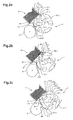
- the initiating element 11.1 In the state shown in Figure 2a, there is a first initiation element 11.1 below the feed stack 2 and contacts the lowest product 5.1 of the stack in the area his free edge. In this position, the initiating element 11.1 has a support function for the stack 2, as this, moreover, exclusively at the lower edge 31 by a freely rotatable roller is supported, which forms the stabilizing agent 25 here. The free edge 32 of the lowest product 5.1 is thus by the initiating element 11.1 in this Timing stabilized dynamically.
- the initiating element 11.1 has (in the side view) a circular segment-like geometry, with respect to the main axis of rotation 9 outside lying and functionally essential surface 13.1 has a curvature.
- This vault will formed so that this outer surface 13.1 as a result of the combination movement of Initiation agent rolls around the axes 12.1 and 9 on the bottom of the product 5.1.
- the paraphrase as "essentially circular-segment-shaped geometry" must not be restrictive be understood. In addition to typically rounded edges, modifications are possible as long as the movement path according to the invention can be described and the mutual movement of initiating element 11 and conveying element 10 according to the invention is ensured (see. for example, Figure 2c, 2d).
- a first conveying element 10.1 is arranged following the initiating element 11.1 in the direction of rotation D 1 and is not yet in function here. Incidentally, the construction corresponds to that of FIG. 1.
- the initiating means 11.1 has one or more suction bores or openings 14.1 emerging on the outer surface 13.1.
- the suction bore 14.1 shown here is located at the edge of the free edge 32 and by an appropriate control causes this edge 32 is detected by building a negative pressure in the suction bore 14.1 in this phase and thereby held non-positively.
- the separating device has moved by almost 20 ° in the direction of rotation D 1 .
- the initiating means 11.1 has in the meantime undergone a clockwise rotation about its axis 12.1 in the direction of rotation D 2 .
- the free edge 32 of the bottommost product 5.1 retained by the initiating element 11.1 was correspondingly lifted off the bottom of the stack and is now at a distance from the free edge of the next product 5.2.
- the conveyor element 10.1 is still without functional effect. It can be seen that the initiation element continues to support the stack 2, now due to its movement at the bottom of the stack a little further from the guide surface 22, which guides the free edges of the products of the stack 2.
- FIG. 2c shows that the separating device rotated by another approximately 20 ° in the direction of rotation D 1 .
- the initiating element 11.1 is now so far rotated about its axis of rotation 12.1 in the direction of rotation D 2 , that the product 5.1 is lifted to a large extent from the stack 2 against bottom and was already released at its free edge 32 from the initiating element 11.1.
- the product 5.1 is stabilized in this position essentially only at its edge 31.
- the initiation element 11.1 lifted due to its circular segment-like geometry from the stack 2 and no longer supports it.
- the conveying element 10.1 in the direction of rotation D 1 so far further rotated that it now supports the stack 2 from below at the free edges on its outer surface 16.1.
- Initiating elements 11 and conveying elements 10 are arranged intermittently in such a way that alternately each one initiating element 11 or a conveying element 10 dynamically stabilize the stack on the free sides. Due to inertia of the stack, it is possible that this dynamically changing stabilization experiences short-term pauses or that during the transition to the subsequent dynamic stabilization element for a short moment both elements participate in the stabilization.
- the conveyor element has (in side view) a flattened, kidney-shaped geometry.
- the correspondingly longer side surface 16.1 is relative to the main axis of rotation 9 against directed outside and the short side surface 17.1 is radially inward.
- the kidney shape These are the two surfaces, namely the functionally significant external surface 16.1, curved.
- the outer surface is here by a uniform radius defined, the shortest distance between the main axis of rotation 9 and the lowest Product of the stack 2 corresponds.
- the Conveying element thus according to the invention has different functional surfaces or edges and ends up.
- An acute-angled end 34a serves to undermine one to be singled Product 5.1, an elongated area 16.1 for detecting the product and a another surface 18a together with the end 34a the pushing back and flipping the Product 5.1.
- the conveyor element 10 serves to (temporarily) stabilize the stack in the region of the free edges (dynamic support of the second lowest product), on the other hand, the transfer of the foremost product 5 is effected by the same conveying element.
- the suction means openings 26
- the suction means which are arranged on the outer edge 16.1 do not suck in air at this stage (but prefer to expel air), since otherwise not the lowermost product but the second lowest product is detected would.
- the conveying element exercises a plurality of functions, partly simultaneously, partly sequentially one after the other, it becoming clear in this embodiment that these are sequentially in a first phase the following: (a) Dynamic support of the stack (see Figure 2c); (b) dynamically supporting the stack and lifting the bottom product (see Figure 2d); (c) dynamically supporting the stack and continuously transferring the product (see Figures 2e and 2f).
- the product 5.1 is not yet complete in the state shown in FIG. 2f isolated, but still - albeit largely detached from this - the Assigned feed stack and at its stabilized edge 31 by the stabilizing agent 25 supported.
- FIG. 2a To explain the second phase of the singulation, reference is made to FIG. 2a directed. There is the lowest product, now provided with the reference numeral 5.1 ', in recognizable in his next position. Over a first (comparatively small) area 33.1 now lies in the stacking position overhead side of the product of the outer surface 16.1 ' of the conveying element 10.1 '.
- Figure 2b shows that upon further rotation of the separating device 1 in the direction of rotation D 1 of the rotary body (aid 3) is synchronized so that its first contact surface 8.1 the delivery element 10.1 'is applied and in this way between these two parts a clamping gap is formed, the forms a conveying means for the intermediate product 5.1 '.
- another aid 3 can be provided which supports the separation in its last phase in terms of force.
- the product is 5.1 'then completely off the clamping gap 28 is conveyed out and finally is only through the conveyor element 10.1 'or detected by the suction means 26 and can at a transfer point 19 to a Further conveyor (see Figure 1) or directly to a printed product or another Subject to be transferred.
- the detachment is preferably carried out by a control of Aspirating means 26 or by suitable transfer means, such as e.g. through a stronger one Force acting suction organs of a transfer device 20 ( Figure 1).
- This one shown suction means 26 can also by others a positive connection with the promotional products 26, e.g. by means of that take advantage of electrostatic adhesion.
- FIG. 3 shows a Section through the separating device 1 along a plane E (see Figure 4), through the Main axis of rotation 9 is running.
- a cylindrical base member 40 is rotatable by means of ball bearings 41 around the geometric axis 9a, mounted on the main axis of rotation 9.
- FIG. 4 shows a Front view of the separating device 1. Corresponding components are the same Reference number marked.
- the section shown in Figure 3 shows a conveying element 10 which is rigidly connected to the base member 40 by means of screws 35.1, 35.2 (see Figure 4).
- the base member 40 has a toothing 42.
- a toothed belt 45 driven by a conventional drive (not shown) engages in this toothing 42 and effects the circulation of the separating device in the counterclockwise direction as explained with reference to the preceding figures (see the direction of rotation D 1 in FIG.
- An initiating element 11 is arranged on a rotation axis 12.
- This axis of rotation 12 is rotatably supported by ball bearings 46 in the base member 40.
- the drive of the axis of rotation 12 via a pinion 36 which engages here in an internal toothing of the stationary housing 15.
- a translation for this drive or a location-dependent control of the rotational speed can be provided.
- sucking and releasing the Products by the conveyor element 10 and the lifting of the products by the Initiation element 11 is in a manner known in the art by means of a pneumatically operated pneumatic system causes.
- About a compressed air pipe 48 is the Pneumatic system Compressed air supplied centrally.
- Several holes 49 serve as distribution channels the compressed air to the conveyor elements 10 and the initiating element 11.
- air distribution chambers are provided.
- Such Luftverteilhunt 47.3 is provided for example in the region of the main axis of rotation 9.
- the Residual air is, unless an outlet on the elements 10, 11 takes place on the Vent ports 50 removed.
- the individual components of the separating device 1 are, where necessary, by means of seals 55, of which only a few by way of example with a reference numeral are sealed airtight against each other, so that the necessary pressure build-up in Pneumatic system can be done.
- the system is constantly pressurized. This air flows via the distribution channels, optionally by an adjustable throttle (not shown) adjustable, to the openings 26.1 to 26.5 on the outer surface 16 of the conveyor element 10 or to the openings 14.1 to 14.3 on the outer surface 13 of the initiating element 11.
- an adjustable throttle not shown
- the distribution channels point for the conveying element 10 a first injector manifold 51 and for the initiating element 11 a second Injector 52 on.
- Injektorverteiler 51, 52 are each a stationary here Control curve 53 and 54 controlled so that air to respective distribution chambers 47.1 and 47.2 the conveying elements 10 and initiating elements 11 passed and these via the openings 14, 26 is ejected.
- Control curve 53 and 54 is controlled so that air to respective distribution chambers 47.1 and 47.2 the conveying elements 10 and initiating elements 11 passed and these via the openings 14, 26 is ejected.
- Depending on the respective cam 53, 54 is in others Areas (or at certain times) of the air flow diverted so that a Vacuum in the distribution chambers 47.1 and 47.2 arises and thereby sucking on the Openings 26 and 14 is effected.
- the control cams 53, 54 are by means of adjusting elements 44th adjustable.
- the thus controlled Injektorverteiler 51, 52 serve in this way, to the openings 14, 26 during certain periods and / or in some areas Outflow of air ("rejects of the product”) and at other intervals or in other areas to suction the air (“collection of the products”) to effect.
- the air distribution in the pneumatic system can be precisely controlled by mechanical means.
- the air supply in the initiating elements 11 in time or be controlled depending on location.
- the sheet products can also be one of a rectangular shape have different geometry.
- the invention also allows that such products are separated.
- the stabilization does not take place then necessarily at an "edge", but can via suitable stabilizing means 25 so be achieved that only a one-off stabilization of the accessible areas, e.g. is effected by one or more freely rotating balls.
- the guide surfaces 21, 22 in this case are suitably replaced by bars or other guide profiles.
- the guide surfaces may also contain movable means which Reduce frictional forces.
- a guide element 37 in the vicinity of the free edges of the Products 5 in the stack 2, a guide element 37 (in Figures 2a to 2c and 2f schematically shown). This serves to ensure that at high processing speeds and / or possible deformations of the free edges 32 of the products 5, ensured is that the conveyor elements 10 exactly between the lowest and second lowest product 5.1, 5.2 retract and not undesirably include the following product or damage (see schematically illustrated positions of the guide element 37 in the figures).
- the initiating elements 11 in their approach to the Stack this in the right position to support, with the guiding element not this hampered ( Figures 2a and 2b).
- This guide element 37 may e.g. as controlled Finger be formed, or as a deformable plastic plate, which at Passage of the conveyor elements 10 passively undergoes elastic deformation and so the second least product retains until the respective element 10, 11 according to the invention dynamic support or stabilization in the right place causes.
- the initiating agent may also be referred to as be formed stationary, controlled element, not with the conveyor elements 10th co-rotates.
- Another design alternative provides for initiating element 11 directly to arrange the conveyor elements 10.
- at the leading end 34a ( Figure 2d) of the Conveying element 10 provided pivotable support members, which undercut the feed stack and lift off the lowest product. Once the conveyor element its dynamic Stabilization can exercise, the support member is back or in the conveying element pivoted.
- the conveying element 10 has a flattened Geometry and is arranged on the separating device 1 so that a to detecting product 5 by a leading side 18a or edge 34a (see Figure 2c) of the Conveying element 10 moves in the direction against the stabilized edge 31 of the product 5 and, as described in more detail below with reference to FIG 5, isolated.
- the conveying element 10 may also be designed in several parts, and for example of two separate, be formed directly behind one another parts.
- the invention makes it possible, the feed stack basically in any spatial Position to arrange, in particular above the separating device, and yet a exact and at high processing speed running separation of products perform.
- the inventive method is each time when refilling the feed stack 2 with additional products each First coated with (additional) adhesive, so that the last product of the The rest of the stack and the first product of the refill stick together. In this way can unwanted interference due to friction or adhesion differences between the Products of the various sub-stacks are avoided.
- the conveyor 10 in this figure only schematically indicated, does not move here on a circular path, but on an elliptical orbit and becomes analogous to the above description during this movement path pivoted. In this way, its functional side surfaces or edges come in desired moment with the products in operative contact.
- a stack 2 of adhesive-coated on one side products 5 is lying here arranged.
- the adhesive 6 is attached to the top of the products and is here through a dash-dotted line indicated.
- the adhesive has the property that the individual Products, e.g. Sticky notes, are detachable from each other, without causing adhesive residue stay visible.
- the adhesive can be applied to the intended products on which the Product is attached, in turn be removable or have a permanent liability.
- the products are coated on the adhesive-coated side by a stabilizing agent 25 (cf. Figure 1) stabilized.
- a conveying element 10 undercuts the product 5 'and displaces it in the direction of movement V 1 .
- the product is lifted from the stack and is strongly supported in position P3 by the conveyor element 10.
- the product is still lying flat, ie the adhesive of the subsequent product still fixes the product 5 'to be removed.
- the dynamic stabilization of the stack 2 which is arranged horizontally in this exemplary embodiment, is of importance here only insofar as it requires a counterforce to lift off the foremost (here the uppermost) product.
- the product 5 ' now firmly held, and further pushed back in the direction of V 1 and comes immediately before its definitive release from the stack in the position P 6th
- the product is detected here over a larger area by the conveyor element 10 and is detached from the stack 2 at position P7.
- the entire lifting and removing process is effected by the conveying element 10, which moves in the direction V 1 , wherein only in the last phase from position P5, the conveying element to overcome the release or release forces according to the invention by an additional aid, preferably a rotary body (see Figure 1) is supported.
- the singulator is 1 preferably a transfer device 20 (see Figure 1) downstream, which the adhesive coated products on the products of determination (in Figure 1 schematically with 56 indicated), printed products or other objects, applied and thereby for this perceives a turning effect.
- the products 5 are only on one edge or on a portion stabilized and free at the remaining areas, i. can in this free Raised areas from the pile.
Landscapes
- Engineering & Computer Science (AREA)
- Mechanical Engineering (AREA)
- Sheets, Magazines, And Separation Thereof (AREA)
- Manufacture Of Motors, Generators (AREA)
- Forming Counted Batches (AREA)
Abstract
Description
- Fig. 1
- eine schematische Seitenansicht der erfindungsgemässen Vorrichtung mit einem Zuführstapel und einer Übernahmevorrichtung;
- Fig. 2a-2f
- eine schematische Bildsequenz des erfindungsgemässen Verfahrens und der Funktionen der einzelnen Vorrichtungselemente;
- Fig. 3
- einen Schnitt durch eine erfindungsgemässe Vereinzelungsvorrichtung entlang einer Ebene durch die Hauptdrehachse;
- Fig. 4
- eine Ansicht der erfindungsgemässen Vereinzelungsvorrichtung;
- Fig. 5
- eine schematische Darstellung des Anhebe- und Vereinzelungsprozesses eines Druckbogens.
Claims (18)
- Verfahren zum Vereinzeln und Weitertransportieren von flexiblen, flächigen Erzeugnissen, insbesondere Haftmittel aufweisenden Papierbogen, mit einem Erzeugnis-Zuführstapel (2), einer Vereinzelungsvorrichtung (1), mindestens einem Förderelement (10), welches an nur an einem Teilbereich stabilisierte Erzeugnisse (5) vereinzelt und diese zu einer Übergabestelle (19) fördert, dadurch gekennzeichnet, dass das Förderelement (10) eine zur Stapelebene (7) im Wesentlichen parallele Bewegungsrichtung (V1) aufweist, die von einem freien Bereich der Erzeugnisse (5) zu einem stabilisierten Bereich der Erzeugnisse (5) verläuft, wobei das Förderelement das vorderste Erzeugnis (5) des Zuführstapels (2) unterläuft und nachfolgend an seiner abgewandten Seite (27) kraftschlüssig erfasst.
- Verfahren nach Patentanspruch 1, dadurch gekennzeichnet, dass die Erzeugnisse (5) im Wesentlichen in der Bewegungsrichtung (V1) bewegt werden, wobei Teilbereiche des Erzeugnisses bei einer stabilisierten Kante (31) eine Krafteinwirkung senkrecht zur Stapelebene (7) erfahren und erst in einer letzten Phase der Vereinzelung (P5 bis P7) die Erzeugnisse eine Bewegungskomponente in Längsrichtung (V3) der Erzeugnisse erfahren,
- Verfahren nach einem der Patentansprüche 1 oder 2, dadurch gekennzeichnet, dass das Erzeugnis (5) zwecks Unterlaufen durch das Förderelement (10) mittels eines mit dem Förderelement (10) gleichlaufenden Initiierungselements (11) angehoben wird.
- Verfahren nach einem der vorstehenden Patentansprüche, dadurch gekennzeichnet, dass abwechselnd ein Initiierungselement (11) und ein Förderelement (10) den Zuführstapel (2) dynamisch abstützen.
- Verfahren nach einem der vorstehenden Patentansprüche, dadurch gekennzeichnet, dass das Förderelement (10) in der letzten Phase des Vereinzelns eines Erzeugnisses (5) mit einem Hilfsmittel (3) zur Überwindung der Lösekraft zusammenwirkt.
- Verfahren nach einem der vorstehenden Patentansprüche, dadurch gekennzeichnet, dass die Erzeugnisse an ihren stabilisierten Bereichen (31) durch ein Stabilisierungsmittel (25) mit beweglichen Teilen unterstützt werden, das in der letzten Phase des Vereinzelns eine Reduktion der Reibungskräfte bewirkt.
- Verfahren nach einem der vorstehenden Patentansprüche, dadurch gekennzeichnet, dass die Erzeugnisse (5) einer der Vereinzelungseinrichtung (1) nachgeschalteten Übernahmevorrichtung (20) übergeben werden, welche die Erzeugnisse wendet und auf Bestimmungsprodukte (56) appliziert.
- Verfahren nach einem der vorstehenden Patentansprüche, dadurch gekennzeichnet, dass mittels eines Pneumatiksystems (47, 48, 49, 50) Luft über Öffnungen (14, 26) an den Förderelementen (10) und Initiierungsmitteln (11 ) gesteuert austritt oder angesaugt wird, wobei phasenweise an einem Teil der Öffnungen (26) eines Fördermittels (10) Luft austritt und an einem anderen Teil der Öffnungen (26) desselben Fördermittels (10) Luft ansaugbar ist.
- Verfahren nach Patentanspruch 8, dadurch gekennzeichnet, dass die Luftverteilung im Pneumatiksystem (47, 48, 49, 50) mittels Steuerkurven (53, 54) in zeitlicher bzw. örtlicher Abhängigkeit gesteuert wird, wobei zeit- und/oder bereichsweise Luft über die Öffnungen (14, 26) ausgestossen oder angesaugt wird.
- Vorrichtung zur Durchführung des Verfahrens nach Patentanspruch 1 mit einem Erzeugnis-Zuführstapel (2), einer Vereinzelungsvorrichtung (1), mindestens einem Förderelement (10), welches an nur an einem Teilbereich stabilisierte Erzeugnisse (5) vereinzelt und diese zu einer Übergabestelle (19) fördert, dadurch gekennzeichnet, dass das Förderelement (10) entlang einer endlosen Bahn umläuft und eine abgeflachte Geometrie aufweist und an der Vereinzelungsvorrichtung (1 ) derart angeordnet ist, dass ein zu erfassendes Erzeugnis (5) durch eine vorlaufende Seite oder Kante (18a, 34a) des Förderelements (10) in Richtung gegen eine stabilisierte Kante (31 ) des Erzeugnisses (5) bewegt, dadurch umgelegt, durch das Förderelement (10) erfasst und weitertransportiert wird.
- Vorrichtung nach Patentanspruch 10, dadurch gekennzeichnet, dass das Förderelement (10) eine abgeflachte, nierenförmige Geometrie aufweist, kontinuierlich um eine Hauptdrehachse (9) umläuft und an einer radial aussen liegenden, längeren Seitenfläche (16.1) mehrere einen Kraftschluss mit den zu fördernden Erzeugnissen (5) herbeiführende Organe (26) aufweist.
- Vorrichtung nach Patentanspruch 10 oder 11, dadurch gekennzeichnet, dass vor dem Förderelement (10) ein entlang dessen Bewegungsbahn mitbewegtes Initiierungsmittel (11) zum initialen Anheben eines Erzeugnisses (5) vom Stapel (2) angeordnet ist.
- Vorrichtung nach Patentanspruch 11, dadurch gekennzeichnet, dass das Initiierungsmittel (11) gegenläufig zur Umlaufrichtung der Förderelemente (10) um eine Achse (12) angetrieben ist.
- Vorrichtung nach einem der Patentansprüche 10 bis 13, dadurch gekennzeichnet, dass im Bereich der stabilisierten Kante (31) des vordersten Erzeugnisses (5) des Zuführstapels (2) ein die Vereinzelung mittels des Fördermittels (10) unterstützendes Hilfsmittel (3) angeordnet ist.
- Vorrichtung nach einem der Patentansprüche 10 bis 14, dadurch gekennzeichnet, dass die Initiierungsmittel (11) eine im Wesentlichen kreissegmentförmige Geometrie aufweisen.
- Vorrichtung nach einem der Patentansprüche 10 bis 15, dadurch gekennzeichnet, dass die Vereinzelungsvorrichtung (1 ) ein Pneumatiksystem (47, 48, 49, 50) aufweist, das mit Öffnungen (14, 26) an den Förderelementen (10) und Initiierungselementen (11) derart verbunden ist, dass an diesen Öffnungen (14, 26) Luft gesteuert austritt oder angesaugt wird.
- Vorrichtung nach einem der Patentansprüche 10 bis 16, dadurch gekennzeichnet, dass im Bereich der freien Kante (32) des zu vereinzelnden Erzeugnisses (5.1) ein Leitelement (37) zwecks Stützung des jeweils nachfolgenden Erzeugnisses (5.2) angeordnet ist.
- Vorrichtung nach Patentanspruch 16, dadurch gekennzeichnet, dass das Pneumatiksystem (47, 48, 49, 50) Injektorverteiler (51, 52) enthält, die mittels Steuerkurven (53, 54) derart steuerbar sind, dass zeit- und/oder bereichsweise Luft über die Öffnungen (14, 26) ausgestossen oder angesaugt wird.
Applications Claiming Priority (2)
| Application Number | Priority Date | Filing Date | Title |
|---|---|---|---|
| CH742004 | 2004-01-21 | ||
| CH742004 | 2004-01-21 |
Publications (2)
| Publication Number | Publication Date |
|---|---|
| EP1557364A1 true EP1557364A1 (de) | 2005-07-27 |
| EP1557364B1 EP1557364B1 (de) | 2011-10-26 |
Family
ID=34624387
Family Applications (1)
| Application Number | Title | Priority Date | Filing Date |
|---|---|---|---|
| EP05000665A Expired - Lifetime EP1557364B1 (de) | 2004-01-21 | 2005-01-14 | Verfahren und Vorrichtung zum Vereinzeln und Weitertransportieren von flexiblen, flächigen Erzeugnissen |
Country Status (6)
| Country | Link |
|---|---|
| US (2) | US7438108B2 (de) |
| EP (1) | EP1557364B1 (de) |
| AT (1) | ATE530453T1 (de) |
| CA (1) | CA2491779A1 (de) |
| DK (1) | DK1557364T3 (de) |
| ES (1) | ES2373723T3 (de) |
Cited By (2)
| Publication number | Priority date | Publication date | Assignee | Title |
|---|---|---|---|---|
| CN105857710A (zh) * | 2015-01-23 | 2016-08-17 | 昆山汉鼎精密金属有限公司 | 自动化贴麦拉夹具 |
| US9857369B2 (en) | 2008-06-30 | 2018-01-02 | Hipep Laboratories | Biochip substratum and method for production thereof |
Families Citing this family (6)
| Publication number | Priority date | Publication date | Assignee | Title |
|---|---|---|---|---|
| JP3862084B2 (ja) * | 2003-10-30 | 2006-12-27 | ホリゾン・インターナショナル株式会社 | 冊子反転装置 |
| CA2491779A1 (en) * | 2004-01-21 | 2005-07-21 | Ferag Ag | A method and a device for separating and for the continued transport of flexible, two-dimensional products |
| US9150324B2 (en) * | 2011-12-13 | 2015-10-06 | New Jersey Machine, Inc. | Systems and methods for dynamically applying outserts to articles |
| JP6691841B2 (ja) * | 2016-06-30 | 2020-05-13 | シブヤマシナリー株式会社 | ラベラ |
| IT202000016705A1 (it) * | 2020-07-09 | 2022-01-09 | Gd Spa | Unità e processo di movimentazione di uno sbozzato ed apparato di confezionamento ad esso associato |
| US11533555B1 (en) | 2021-07-07 | 2022-12-20 | Bose Corporation | Wearable audio device with enhanced voice pick-up |
Citations (5)
| Publication number | Priority date | Publication date | Assignee | Title |
|---|---|---|---|---|
| US3572691A (en) | 1967-11-01 | 1971-03-30 | Canadian Stackpole Ltd | Mechanism for withdrawing individual sheets of paper from a stack |
| US4021293A (en) | 1975-11-07 | 1977-05-03 | Stackpole Machinery Company | High speed labeling machine |
| US4619726A (en) | 1985-05-13 | 1986-10-28 | Westvaco Corporation | Label applicator |
| US4981235A (en) | 1988-03-28 | 1991-01-01 | Targa Industries, Inc. | Unitary coupon dispenser |
| EP1086914A1 (de) * | 1999-09-24 | 2001-03-28 | Ferag AG | Vorrichtung zum Transport von flexiblen, flächigen Erzeugnissen |
Family Cites Families (7)
| Publication number | Priority date | Publication date | Assignee | Title |
|---|---|---|---|---|
| CA1090303A (en) | 1977-10-11 | 1980-11-25 | Horst A. Benoit | Device for controlling tilt of labelling pad on labelling apparatus |
| US4293365A (en) * | 1980-08-01 | 1981-10-06 | Crown Zellerbach Corporation | Apparatus for applying labels or the like |
| CH684589A5 (de) | 1992-03-09 | 1994-10-31 | Grapha Holding Ag | Verfahren und Vorrichtung zum Vereinzeln von in einem stationären Bogenmagazin gestapelten Druckbogen. |
| AU5807996A (en) | 1995-06-06 | 1996-12-24 | Systematic Packaging Controls Corporation | Produce labeller |
| DE69804789D1 (de) | 1997-06-12 | 2002-05-16 | Add On Internat B V | Verfahren und vorrichtung zum befestigen von beilagen auf bewegten objekte |
| IT1294334B1 (it) | 1997-08-20 | 1999-03-24 | Sitma Spa | Dispositivo di rotazione di una etichetta elimentata in una etichettatrice |
| CA2491779A1 (en) * | 2004-01-21 | 2005-07-21 | Ferag Ag | A method and a device for separating and for the continued transport of flexible, two-dimensional products |
-
2005
- 2005-01-10 CA CA002491779A patent/CA2491779A1/en not_active Abandoned
- 2005-01-14 AT AT05000665T patent/ATE530453T1/de active
- 2005-01-14 ES ES05000665T patent/ES2373723T3/es not_active Expired - Lifetime
- 2005-01-14 EP EP05000665A patent/EP1557364B1/de not_active Expired - Lifetime
- 2005-01-14 DK DK05000665.9T patent/DK1557364T3/da active
- 2005-01-21 US US11/038,494 patent/US7438108B2/en not_active Expired - Fee Related
-
2008
- 2008-09-03 US US12/231,445 patent/US20090001654A1/en not_active Abandoned
Patent Citations (5)
| Publication number | Priority date | Publication date | Assignee | Title |
|---|---|---|---|---|
| US3572691A (en) | 1967-11-01 | 1971-03-30 | Canadian Stackpole Ltd | Mechanism for withdrawing individual sheets of paper from a stack |
| US4021293A (en) | 1975-11-07 | 1977-05-03 | Stackpole Machinery Company | High speed labeling machine |
| US4619726A (en) | 1985-05-13 | 1986-10-28 | Westvaco Corporation | Label applicator |
| US4981235A (en) | 1988-03-28 | 1991-01-01 | Targa Industries, Inc. | Unitary coupon dispenser |
| EP1086914A1 (de) * | 1999-09-24 | 2001-03-28 | Ferag AG | Vorrichtung zum Transport von flexiblen, flächigen Erzeugnissen |
Cited By (3)
| Publication number | Priority date | Publication date | Assignee | Title |
|---|---|---|---|---|
| US9857369B2 (en) | 2008-06-30 | 2018-01-02 | Hipep Laboratories | Biochip substratum and method for production thereof |
| CN105857710A (zh) * | 2015-01-23 | 2016-08-17 | 昆山汉鼎精密金属有限公司 | 自动化贴麦拉夹具 |
| CN105857710B (zh) * | 2015-01-23 | 2018-11-06 | 昆山汉鼎精密金属有限公司 | 自动化贴麦拉夹具 |
Also Published As
| Publication number | Publication date |
|---|---|
| US20050189696A1 (en) | 2005-09-01 |
| DK1557364T3 (da) | 2011-11-21 |
| US20090001654A1 (en) | 2009-01-01 |
| ATE530453T1 (de) | 2011-11-15 |
| ES2373723T3 (es) | 2012-02-08 |
| US7438108B2 (en) | 2008-10-21 |
| CA2491779A1 (en) | 2005-07-21 |
| EP1557364B1 (de) | 2011-10-26 |
Similar Documents
| Publication | Publication Date | Title |
|---|---|---|
| EP2253566B1 (de) | Vorrichtung zur Beschickung einer Verarbeitungsstrecke mit Druckprodukten | |
| DE69601123T2 (de) | Vorrichtung und Verfahren zum Anbringen eines rohrförmigen Elements um einen Gegenstand | |
| DE102011082450A1 (de) | Vorrichtung zum selektiven Lösen von auf einem Trägerband angeordneten Etiketten | |
| EP0368009A1 (de) | Verfahren und Vorrichtung zum Fördern von Druckereiprodukten | |
| EP2690040B1 (de) | Vorrichtung zum Abtrennen von einzelnen flachen, biegbaren Gegenständen von der Unterseite eines Stapels solcher Gegenstände | |
| EP1557364B1 (de) | Verfahren und Vorrichtung zum Vereinzeln und Weitertransportieren von flexiblen, flächigen Erzeugnissen | |
| EP2763921B1 (de) | Vorrichtung und verfahren zum bereitstellen von folienblättern, appliziervorrichtung zum bestücken von gegenständen mit folienblättern | |
| EP2133295B1 (de) | Vorrichtung und Verfahren zum Entnehmen flacher Druckprodukte aus einem Stapel und zum Übergeben der Druckprodukte an eine laufende Transportvorrichtung | |
| DE10219982C1 (de) | Verfahren und Vorrichtung zur Vereinzelung von gestapelten Zuschnitten | |
| EP1193201B1 (de) | Verfahren und Vorrichtung zur Bildung einer Doppelschuppenformation aus Druckereiprodukten | |
| EP1520817B1 (de) | Einrichtung zur Herstellung gebundener Bücher, Zeitschriften oder Broschüren | |
| EP1351873A1 (de) | Vorrichtung zum verarbeiten von druckereiprodukten | |
| EP2524889B1 (de) | Verfahren und Vorrichtung zur Übergabe von Druckprodukten | |
| DE2717554A1 (de) | Verfahren und einrichtung zum ausrichten und zufuehren von bogen an druckmaschinen | |
| EP2228332B1 (de) | Vorrichtung und Verfahren zum Übernehmen von flexiblen, flächigen Gegenständen | |
| DE4133404A1 (de) | Vorrichtung zum foerdern von aufklebern | |
| EP1426293A1 (de) | Verfahren und Vorrichtung zum Verpacken von flachen Gegenständen | |
| EP1669312B1 (de) | Vorrichtung zum on-line Weitertransport von flachen Gegenständen, die von einer zuführenden Vorrichtung auf einem Träger gestapelt werden | |
| EP1657199B1 (de) | Vorrichtung zum Bearbeiten von flachen Produkten, insbesondere Druckprodukten | |
| DE102010008619A1 (de) | Vorrichtung zum Vereinzeln von scheibenförmigen Elementen | |
| EP1655244B1 (de) | Verfahren und Vorrichtung zur Vereinzelung von flachen Gegenständen aus einem liegenden Stapel | |
| DE102007039259B3 (de) | Zuführvorrichtung und Verfahren zur Zuführung von Bögen von einem Stapel | |
| DE3113023C2 (de) | Vorrichtung zum Schichten von verschiedenartigen Bögen | |
| EP1471022A1 (de) | Sammelvorrichtung und Verfahren zu deren Betrieb | |
| EP1748012B1 (de) | Verfahren und Vorrichtung zum Zusammentragen von Druckbogen |
Legal Events
| Date | Code | Title | Description |
|---|---|---|---|
| PUAI | Public reference made under article 153(3) epc to a published international application that has entered the european phase |
Free format text: ORIGINAL CODE: 0009012 |
|
| AK | Designated contracting states |
Kind code of ref document: A1 Designated state(s): AT BE BG CH CY CZ DE DK EE ES FI FR GB GR HU IE IS IT LI LT LU MC NL PL PT RO SE SI SK TR |
|
| AX | Request for extension of the european patent |
Extension state: AL BA HR LV MK YU |
|
| 17P | Request for examination filed |
Effective date: 20060127 |
|
| AKX | Designation fees paid |
Designated state(s): AT BE BG CH CY CZ DE DK EE ES FI FR GB GR HU IE IS IT LI LT LU MC NL PL PT RO SE SI SK TR |
|
| 17Q | First examination report despatched |
Effective date: 20070202 |
|
| GRAP | Despatch of communication of intention to grant a patent |
Free format text: ORIGINAL CODE: EPIDOSNIGR1 |
|
| GRAS | Grant fee paid |
Free format text: ORIGINAL CODE: EPIDOSNIGR3 |
|
| GRAA | (expected) grant |
Free format text: ORIGINAL CODE: 0009210 |
|
| AK | Designated contracting states |
Kind code of ref document: B1 Designated state(s): AT BE BG CH CY CZ DE DK EE ES FI FR GB GR HU IE IS IT LI LT LU MC NL PL PT RO SE SI SK TR |
|
| REG | Reference to a national code |
Ref country code: GB Ref legal event code: FG4D Free format text: NOT ENGLISH |
|
| REG | Reference to a national code |
Ref country code: CH Ref legal event code: NV Representative=s name: RENTSCH PARTNER AG Ref country code: CH Ref legal event code: EP |
|
| REG | Reference to a national code |
Ref country code: DK Ref legal event code: T3 |
|
| REG | Reference to a national code |
Ref country code: IE Ref legal event code: FG4D |
|
| REG | Reference to a national code |
Ref country code: DE Ref legal event code: R096 Ref document number: 502005012060 Country of ref document: DE Effective date: 20111215 |
|
| REG | Reference to a national code |
Ref country code: ES Ref legal event code: FG2A Ref document number: 2373723 Country of ref document: ES Kind code of ref document: T3 Effective date: 20120208 |
|
| REG | Reference to a national code |
Ref country code: NL Ref legal event code: VDEP Effective date: 20111026 |
|
| LTIE | Lt: invalidation of european patent or patent extension |
Effective date: 20111026 |
|
| PG25 | Lapsed in a contracting state [announced via postgrant information from national office to epo] |
Ref country code: IS Free format text: LAPSE BECAUSE OF FAILURE TO SUBMIT A TRANSLATION OF THE DESCRIPTION OR TO PAY THE FEE WITHIN THE PRESCRIBED TIME-LIMIT Effective date: 20120226 Ref country code: LT Free format text: LAPSE BECAUSE OF FAILURE TO SUBMIT A TRANSLATION OF THE DESCRIPTION OR TO PAY THE FEE WITHIN THE PRESCRIBED TIME-LIMIT Effective date: 20111026 |
|
| PG25 | Lapsed in a contracting state [announced via postgrant information from national office to epo] |
Ref country code: NL Free format text: LAPSE BECAUSE OF FAILURE TO SUBMIT A TRANSLATION OF THE DESCRIPTION OR TO PAY THE FEE WITHIN THE PRESCRIBED TIME-LIMIT Effective date: 20111026 Ref country code: PL Free format text: LAPSE BECAUSE OF FAILURE TO SUBMIT A TRANSLATION OF THE DESCRIPTION OR TO PAY THE FEE WITHIN THE PRESCRIBED TIME-LIMIT Effective date: 20111026 Ref country code: SI Free format text: LAPSE BECAUSE OF FAILURE TO SUBMIT A TRANSLATION OF THE DESCRIPTION OR TO PAY THE FEE WITHIN THE PRESCRIBED TIME-LIMIT Effective date: 20111026 Ref country code: SE Free format text: LAPSE BECAUSE OF FAILURE TO SUBMIT A TRANSLATION OF THE DESCRIPTION OR TO PAY THE FEE WITHIN THE PRESCRIBED TIME-LIMIT Effective date: 20111026 Ref country code: GR Free format text: LAPSE BECAUSE OF FAILURE TO SUBMIT A TRANSLATION OF THE DESCRIPTION OR TO PAY THE FEE WITHIN THE PRESCRIBED TIME-LIMIT Effective date: 20120127 Ref country code: PT Free format text: LAPSE BECAUSE OF FAILURE TO SUBMIT A TRANSLATION OF THE DESCRIPTION OR TO PAY THE FEE WITHIN THE PRESCRIBED TIME-LIMIT Effective date: 20120227 |
|
| REG | Reference to a national code |
Ref country code: IE Ref legal event code: FD4D |
|
| PG25 | Lapsed in a contracting state [announced via postgrant information from national office to epo] |
Ref country code: CY Free format text: LAPSE BECAUSE OF FAILURE TO SUBMIT A TRANSLATION OF THE DESCRIPTION OR TO PAY THE FEE WITHIN THE PRESCRIBED TIME-LIMIT Effective date: 20111026 |
|
| BERE | Be: lapsed |
Owner name: FERAG AG Effective date: 20120131 |
|
| PG25 | Lapsed in a contracting state [announced via postgrant information from national office to epo] |
Ref country code: CZ Free format text: LAPSE BECAUSE OF FAILURE TO SUBMIT A TRANSLATION OF THE DESCRIPTION OR TO PAY THE FEE WITHIN THE PRESCRIBED TIME-LIMIT Effective date: 20111026 Ref country code: BG Free format text: LAPSE BECAUSE OF FAILURE TO SUBMIT A TRANSLATION OF THE DESCRIPTION OR TO PAY THE FEE WITHIN THE PRESCRIBED TIME-LIMIT Effective date: 20120126 Ref country code: SK Free format text: LAPSE BECAUSE OF FAILURE TO SUBMIT A TRANSLATION OF THE DESCRIPTION OR TO PAY THE FEE WITHIN THE PRESCRIBED TIME-LIMIT Effective date: 20111026 Ref country code: IE Free format text: LAPSE BECAUSE OF FAILURE TO SUBMIT A TRANSLATION OF THE DESCRIPTION OR TO PAY THE FEE WITHIN THE PRESCRIBED TIME-LIMIT Effective date: 20111026 Ref country code: EE Free format text: LAPSE BECAUSE OF FAILURE TO SUBMIT A TRANSLATION OF THE DESCRIPTION OR TO PAY THE FEE WITHIN THE PRESCRIBED TIME-LIMIT Effective date: 20111026 |
|
| PG25 | Lapsed in a contracting state [announced via postgrant information from national office to epo] |
Ref country code: MC Free format text: LAPSE BECAUSE OF NON-PAYMENT OF DUE FEES Effective date: 20120131 Ref country code: IT Free format text: LAPSE BECAUSE OF FAILURE TO SUBMIT A TRANSLATION OF THE DESCRIPTION OR TO PAY THE FEE WITHIN THE PRESCRIBED TIME-LIMIT Effective date: 20111026 Ref country code: RO Free format text: LAPSE BECAUSE OF FAILURE TO SUBMIT A TRANSLATION OF THE DESCRIPTION OR TO PAY THE FEE WITHIN THE PRESCRIBED TIME-LIMIT Effective date: 20111026 |
|
| PLBE | No opposition filed within time limit |
Free format text: ORIGINAL CODE: 0009261 |
|
| REG | Reference to a national code |
Ref country code: CH Ref legal event code: PL |
|
| STAA | Information on the status of an ep patent application or granted ep patent |
Free format text: STATUS: NO OPPOSITION FILED WITHIN TIME LIMIT |
|
| REG | Reference to a national code |
Ref country code: DK Ref legal event code: EBP |
|
| GBPC | Gb: european patent ceased through non-payment of renewal fee |
Effective date: 20120126 |
|
| 26N | No opposition filed |
Effective date: 20120727 |
|
| REG | Reference to a national code |
Ref country code: FR Ref legal event code: ST Effective date: 20120928 |
|
| PG25 | Lapsed in a contracting state [announced via postgrant information from national office to epo] |
Ref country code: DE Free format text: LAPSE BECAUSE OF NON-PAYMENT OF DUE FEES Effective date: 20120801 Ref country code: GB Free format text: LAPSE BECAUSE OF NON-PAYMENT OF DUE FEES Effective date: 20120126 Ref country code: LI Free format text: LAPSE BECAUSE OF NON-PAYMENT OF DUE FEES Effective date: 20120131 Ref country code: CH Free format text: LAPSE BECAUSE OF NON-PAYMENT OF DUE FEES Effective date: 20120131 |
|
| REG | Reference to a national code |
Ref country code: DE Ref legal event code: R119 Ref document number: 502005012060 Country of ref document: DE Effective date: 20120801 |
|
| REG | Reference to a national code |
Ref country code: DE Ref legal event code: R097 Ref document number: 502005012060 Country of ref document: DE Effective date: 20120727 |
|
| PG25 | Lapsed in a contracting state [announced via postgrant information from national office to epo] |
Ref country code: FR Free format text: LAPSE BECAUSE OF NON-PAYMENT OF DUE FEES Effective date: 20120131 Ref country code: BE Free format text: LAPSE BECAUSE OF NON-PAYMENT OF DUE FEES Effective date: 20120131 |
|
| PG25 | Lapsed in a contracting state [announced via postgrant information from national office to epo] |
Ref country code: DK Free format text: LAPSE BECAUSE OF NON-PAYMENT OF DUE FEES Effective date: 20120131 |
|
| REG | Reference to a national code |
Ref country code: AT Ref legal event code: MM01 Ref document number: 530453 Country of ref document: AT Kind code of ref document: T Effective date: 20120114 |
|
| PG25 | Lapsed in a contracting state [announced via postgrant information from national office to epo] |
Ref country code: AT Free format text: LAPSE BECAUSE OF NON-PAYMENT OF DUE FEES Effective date: 20120114 Ref country code: FI Free format text: LAPSE BECAUSE OF FAILURE TO SUBMIT A TRANSLATION OF THE DESCRIPTION OR TO PAY THE FEE WITHIN THE PRESCRIBED TIME-LIMIT Effective date: 20111026 |
|
| REG | Reference to a national code |
Ref country code: ES Ref legal event code: FD2A Effective date: 20130708 |
|
| PG25 | Lapsed in a contracting state [announced via postgrant information from national office to epo] |
Ref country code: ES Free format text: LAPSE BECAUSE OF NON-PAYMENT OF DUE FEES Effective date: 20120115 |
|
| PG25 | Lapsed in a contracting state [announced via postgrant information from national office to epo] |
Ref country code: TR Free format text: LAPSE BECAUSE OF FAILURE TO SUBMIT A TRANSLATION OF THE DESCRIPTION OR TO PAY THE FEE WITHIN THE PRESCRIBED TIME-LIMIT Effective date: 20111026 |
|
| PG25 | Lapsed in a contracting state [announced via postgrant information from national office to epo] |
Ref country code: LU Free format text: LAPSE BECAUSE OF NON-PAYMENT OF DUE FEES Effective date: 20120114 |
|
| PG25 | Lapsed in a contracting state [announced via postgrant information from national office to epo] |
Ref country code: HU Free format text: LAPSE BECAUSE OF FAILURE TO SUBMIT A TRANSLATION OF THE DESCRIPTION OR TO PAY THE FEE WITHIN THE PRESCRIBED TIME-LIMIT Effective date: 20050114 |