EP1556255B1 - Sensor device and method for detecting an external impact load on a vehicle - Google Patents
Sensor device and method for detecting an external impact load on a vehicle Download PDFInfo
- Publication number
- EP1556255B1 EP1556255B1 EP03747942A EP03747942A EP1556255B1 EP 1556255 B1 EP1556255 B1 EP 1556255B1 EP 03747942 A EP03747942 A EP 03747942A EP 03747942 A EP03747942 A EP 03747942A EP 1556255 B1 EP1556255 B1 EP 1556255B1
- Authority
- EP
- European Patent Office
- Prior art keywords
- sensor
- sensor device
- impact
- sensor line
- line
- Prior art date
- Legal status (The legal status is an assumption and is not a legal conclusion. Google has not performed a legal analysis and makes no representation as to the accuracy of the status listed.)
- Expired - Fee Related
Links
Images


Classifications
-
- B—PERFORMING OPERATIONS; TRANSPORTING
- B60—VEHICLES IN GENERAL
- B60R—VEHICLES, VEHICLE FITTINGS, OR VEHICLE PARTS, NOT OTHERWISE PROVIDED FOR
- B60R21/00—Arrangements or fittings on vehicles for protecting or preventing injuries to occupants or pedestrians in case of accidents or other traffic risks
- B60R21/01—Electrical circuits for triggering passive safety arrangements, e.g. airbags, safety belt tighteners, in case of vehicle accidents or impending vehicle accidents
- B60R21/013—Electrical circuits for triggering passive safety arrangements, e.g. airbags, safety belt tighteners, in case of vehicle accidents or impending vehicle accidents including means for detecting collisions, impending collisions or roll-over
- B60R21/0136—Electrical circuits for triggering passive safety arrangements, e.g. airbags, safety belt tighteners, in case of vehicle accidents or impending vehicle accidents including means for detecting collisions, impending collisions or roll-over responsive to actual contact with an obstacle, e.g. to vehicle deformation, bumper displacement or bumper velocity relative to the vehicle
-
- B—PERFORMING OPERATIONS; TRANSPORTING
- B60—VEHICLES IN GENERAL
- B60R—VEHICLES, VEHICLE FITTINGS, OR VEHICLE PARTS, NOT OTHERWISE PROVIDED FOR
- B60R21/00—Arrangements or fittings on vehicles for protecting or preventing injuries to occupants or pedestrians in case of accidents or other traffic risks
- B60R21/34—Protecting non-occupants of a vehicle, e.g. pedestrians
Definitions
- the invention relates to a sensor device for detecting an external impact load on a vehicle, in particular in a pedestrian impact, and to a corresponding method.
- the DE 100 23 588 A discloses the preamble of claim 1.
- the object of the invention is to improve a sensor device and a corresponding sensing method of the type specified above so that a selective and reliable impact detection or collision detection is achieved especially in a design suitable for economical mass production.
- the invention proposes that a sensor device for detecting an external impact load on a vehicle, in particular in a pedestrian impact, responsive to mechanical deformation sensor line, a sensor line receiving support body and cooperating with the sensor line measuring unit for providing a shock signal, wherein the support body Having a deforming structure in engagement with the sensor line for over the length of the sensor line partially varying pressure force transmission.
- the deformation structure comprises a plurality of force transmission members arranged distributed along the sensor line at unequal distances from each other as adjustment means.
- the signal transmission in the sensor line is influenced by the deformation structure during a shock load due to mechanical deformation.
- the pressure force transmission via adaptation means arranged along the sensor line can be adapted to the load resistance of the surrounding vehicle parts.
- a particularly preferred embodiment provides that the pressure force transmission is adjusted so that the shock signal for a given impact load remains independent of the load point. In this way, it is possible to evaluate the impact strength location-independent with low error rate.
- the support body has an irregularly variable flexural rigidity along the sensor line due to changes in the cross section or in the material density or through openings or recesses or the like adjustment means.
- the support body has an elastically deformable spacer with along the sensor line varying elasticity. This can be achieved by providing at least one longitudinal web which extends along the sensor line and can be bent or bent under transverse load, wherein the longitudinal web has a variable wall thickness or wall weakening for adapting its transverse rigidity.
- the deformation structure acts on the sensor line under local bending stress.
- a plurality of sensor lines are arranged side by side.
- a plurality of sensor lines having the deformation structure engaged active portions and disengaged blind portions have.
- the length of the sections is different in a line.
- a further improvement provides that the length of the active and dummy sections with respect to a series of sensor lines decreases in a fixed ratio.
- the deformation structure has two comb-shaped deformation bodies, the sensor conduit preferably extending linearly between the deformation bodies intermeshing during impact loading.
- the sensor line is formed by at least one optical fiber.
- other sensors are also conceivable, for example piezoelectric, pneumatic or hydraulic transducer cables or cables.
- the or each sensor line has two line sections running next to one another, preferably connected continuously via a loop.
- a shock signal is generated by an responsive to mechanical deformation sensor line, wherein the pressure force transmission to the sensor line is locally varied by a deformation structure, so that the measurement signal for a given shock load remains independent of the load point.
- a further advantageous measure consists in that light is fed into an optical fiber of a sensor device and the transmission of light in the optical fiber is influenced by bending radius changes, a signal change of the light signal decoupled from the optical fiber being evaluated as a burst signal.
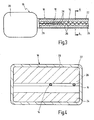
- the sensor device 10 shown in the drawing can generally be used to detect an external impact load on a vehicle 12 and is used in particular for detecting a pedestrian impact.
- the sensor device comprises a sensor line 14, an elongated support body 16 accommodating the sensor line, a deformation structure 18 contained in the support body and a measuring unit 20 cooperating with the sensor line for providing a measurement or shock signal.
- the deformation structure 18 has two comb-like sections 22, 24, which are limited against each other in an external force under local bending stress of the linear sensor line 14 are movable.
- the bending stress is achieved by force transmitting members 26 engaging laterally on the sensor line 14, which are arranged distributed over the length of the sensor line at irregular intervals.
- the sensor line 14 is formed by an optical fiber or a fiber optic cable, the two mutually parallel, on the in Fig. 3 Not shown end, for example, via a loop continuously connected fiber sections. Their light entry and exit ends are coupled to the opto-electronic measuring unit 20. In the measuring unit 20, the evaluation software can be loaded, so that no separate control unit is necessary. The entire assembly is sealed in a receiving shell 28 and can be so easily integrated into the vehicle 12. It is also possible that the sensor line 14 has further optical cable, not shown, which are used for example for reference measurements.
- the sensor line 14 extends along the front bumper 30 of the vehicle 12, wherein the support body 16 between a front side absorber body 32 and a rear cross member 34 is included. It is also conceivable to install the sensor device 10 in a cavity of a side door 36 in order to detect a side crash. Another application could be to detect a pinching situation in the area of electrically operated side windows or in the area of the sunroof.
- the optical fiber 14 is bent in a wave shape at the relevant point of loading by the transmission elements 26 of the deformation structure 18, so that the measuring light passed through undergoes an intensity change or damping.
- a (negative) signal peak 38 in the signal curve results in accordance with the extent of the instantaneous deformation. Its amplitude serves as a measure of the impact strength. It is by the s.den Installation conditions adapted design of the deformation structure 18 allows absolute value detection.
- the waveform 40 outside the signal peak 38 for continuous self-diagnosis of the sensor device 10.
- a system-related damping component occurs, which depends on the temperature, the preload and other design parameters Fig. 5 caused exaggerated drift.
- the dynamic signals 38 occur in fractions of a second, the time scale of the signal drift is significantly higher.
- the slowly varying signal level is compared with a predetermined threshold value 42, above which a sensor error is diagnosed. It is advantageous if the threshold value 42 is selected as a function of the maximum dynamic signal to be detected in such a way that essentially the full peak amplitude can always be detected.
- the threshold value does not have to be kept constant, but can also be updated, for example, depending on operating and environmental parameters.
- the support body directly surrounds the glass fiber line or optical fiber 14 and, in the case of mechanical deformation, influences the mantle refractive index and thus the transmission or attenuation of the light signal in the glass fiber line.
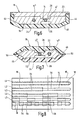
- Embodiments shown differ from the embodiment according to 3 and 4 in that the comb-like intermeshing force transmission members 26 are arranged at the same distance from each other, while the lateral connecting walls 44, 46 act on the deformation bodies 22,24 as elastic spacers with optionally variable stiffness. In this way, the power transmission along the light guide 14 can be variably adjusted.
- the wall slope 48 acts like a leaf spring to the Adjust measuring range.
- Fig. 7 are for this purpose connected to the splice 50 side walls 46 laterally elastically reinforcedbickbar. In both cases, only one line section 14 'is subject to deformation, whereas the section 14 "returned via a loop remains undeformed in, for example, a foamed potting compound 52.
- a plurality of mutually parallel optical fiber 14 as a series of lines (L1 - L5) may be provided, wherein the series members in sections with the deformation structure 18 engaging operative portions 54 and thereof, for example via a cover, not shown unaffected blind portions 56.
- the effective sections of two series links each (L1, L2, L2, L3 ...) are in the length ratio of 2: 1.
- a distribution of force for example, in the region of the longitudinal section 58 can be detected by a simultaneous signal of the lines L1, L3 and L4 in the absence of signal of the other lines.
- the sensor line or the bundle of wires should run far forward of the vehicle in order to detect the impact as early as possible.
- a low level of force must be detectable in order to distinguish a pedestrian collision from a hard impact on solid objects.
- the sensor device can also be used to forward signals from the early impact detection to safety devices such as airbags and crash boxes.
- safety devices such as airbags and crash boxes.
- the crash boxes it is also possible to set the crash boxes so that they are set soft in a pedestrian impact and harder in a different impact. In this case, the soft setting should be selected as the default to protect the pedestrian with priority.
Abstract
Description
Die Erfindung betrifft eine Sensoreinrichtung zur Erfassung einer äußeren Stoßbelastung an einem Fahrzeug, insbesondere bei einem Fußgängeraufprall, sowie ein entsprechendes Verfahren.The invention relates to a sensor device for detecting an external impact load on a vehicle, in particular in a pedestrian impact, and to a corresponding method.
Die fortschreitenden Anforderungen an den Personenschutz im Kraftfahrzeugverkehr machen es erforderlich, kritische Situationen äußerst rasch und zuverlässig zu detektieren, um geeignete Schutzvorkehrungen treffen zu können. Insbesondere soll bei einer Kollision eines Kraftfahrzeugs mit einem Fußgänger auch die Aufprallschwere erkannt werden, um noch mögliche verletzungsmindernde Gegenmaßnahmen auslösen zu können. Problematisch ist es allerdings, den großen Bereich möglicher Aufprallstellen mit Einzelsensoren sicher zu erfassen, wobei unterschiedliche Einbaustellen die Absolutbewertung einer Unfallsituation weiter erschweren.The increasing requirements for personal protection in motor traffic make it necessary to detect critical situations extremely quickly and reliably in order to be able to take suitable precautions. In particular, in a collision of a motor vehicle with a pedestrian and the impact severity should be recognized in order to trigger any possible injury-reducing countermeasures can. However, it is problematic to reliably detect the large area of possible impact points with individual sensors, with different mounting sites further complicating the absolute evaluation of an accident situation.
Die
Ausgehend hiervon liegt der Erfindung die Aufgabe zugrunde, eine Sensoreinrichtung und ein entsprechendes Sensierverfahren der vorstehend angegebenen Art dahingehend zu verbessern, dass eine selektive und sichere Aufprallerkennung bzw. Kollisionserfassung speziell in einer für die wirtschaftliche Massenfertigung geeigneten Bauform erreicht wird.Proceeding from this, the object of the invention is to improve a sensor device and a corresponding sensing method of the type specified above so that a selective and reliable impact detection or collision detection is achieved especially in a design suitable for economical mass production.
Zur Lösung dieser Aufgabe wird die in den unabhängigen Patentansprüchen jeweils angegebene Merkmalskombination vorgeschlagen. Vorteilhafte Ausgestaltungen und Weiterbildungen der Erfindung ergeben sich aus den abhängigen Ansprüchen.To solve this problem, the combination of features specified in the independent claims is proposed. Advantageous embodiments and modifications of the invention will become apparent from the dependent claims.
Dementsprechend wird erfindungsgemäß vorgeschlagen, dass eine Sensoreinrichtung zur Erfassung einer äußeren Stoßbelastung an einem Fahrzeug, insbesondere bei einem Fußgängeraufprall, eine auf mechanische Verformung ansprechende Sensorleitung, einen die Sensorleitung aufnehmenden Tragkörper und eine mit der Sensorleitung zusammenwirkende Messeinheit zur Bereitstellung eines Stoßsignals umfasst, wobei der Tragkörper eine mit der Sensorleitung in Eingriff stehende Verformungsstruktur zur über die Länge der Sensorleitung abschnittsweise variierenden Druckkraftübertragung aufweist. Durch die Verwendung einer Sensorleitung ist es möglich, einen großen Außenbereich des Fahrzeugs abzutasten, ohne dass eine Vielzahl von Einzelfühlern erforderlich wäre. Durch die Anpassung der Kraftübertragung mittels einer Verformungsstruktur kann berücksichtigt werden, dass die Einbaubedingungen und damit die Kraftübertragungscharakteristik über die Geometrie des Fahrzeugs variieren.Accordingly, the invention proposes that a sensor device for detecting an external impact load on a vehicle, in particular in a pedestrian impact, responsive to mechanical deformation sensor line, a sensor line receiving support body and cooperating with the sensor line measuring unit for providing a shock signal, wherein the support body Having a deforming structure in engagement with the sensor line for over the length of the sensor line partially varying pressure force transmission. By using a sensor line, it is possible to scan a large outdoor area of the vehicle without the need for a large number of individual sensors. By adjusting the power transmission by means of a deformation structure can be considered that the installation conditions and thus the power transmission characteristic vary over the geometry of the vehicle.
Um die Kraftübertragung anzupassen, weist die Verformungsstruktur eine Mehrzahl von längs der Sensorleitung in ungleichmäßigen Abständen voneinander verteilt angeordneten Kraftübertragungsgliedern als Anpassungsmittel auf.In order to adjust the power transmission, the deformation structure comprises a plurality of force transmission members arranged distributed along the sensor line at unequal distances from each other as adjustment means.
Vorteilhafterweise wird über die Verformungsstruktur die Signaldurchleitung in der Sensorleitung bei einer Stoßbelastung durch mechanische Verformung beeinflusst.Advantageously, the signal transmission in the sensor line is influenced by the deformation structure during a shock load due to mechanical deformation.
Für eine Auswertung der Signalhöhe ist es von Vorteil, wenn die Druckkraftübertragung über längs der Sensorleitung angeordnete Anpassungsmittel an die Belastungsfestigkeit der umgebenden Fahrzeugteile anpassbar ist.For an evaluation of the signal level, it is advantageous if the pressure force transmission via adaptation means arranged along the sensor line can be adapted to the load resistance of the surrounding vehicle parts.
Eine besonders bevorzugte Ausführung sieht vor, dass die Druckkraftübertragung so angepasst ist, dass das Stoßsignal bei gegebener Stoßbelastung unabhängig von der Belastungsstelle bleibt. Auf diese Weise ist es möglich, die Aufprallstärke ortsunabhängig mit geringer Fehlerrate auszuwerten.A particularly preferred embodiment provides that the pressure force transmission is adjusted so that the shock signal for a given impact load remains independent of the load point. In this way, it is possible to evaluate the impact strength location-independent with low error rate.
Zur lokalen Modifizierung der Sensorempfindlichkeit ist es auch vorteilhaft, wenn der Tragkörper durch Änderungen im Querschnitt oder in der Materialdichte oder durch Durchbrüche oder Ausnehmungen oder dergleichen Anpassungsmittel eine unregelmäßig veränderliche Biegesteifigkeit längs der Sensorleitung aufweist.For local modification of the sensor sensitivity, it is also advantageous if the support body has an irregularly variable flexural rigidity along the sensor line due to changes in the cross section or in the material density or through openings or recesses or the like adjustment means.
Eine vorteilhafte Ausgestaltung sieht vor, dass der Tragkörper einen elastisch verformbaren Abstandhalter mit längs der Sensorleitung variierender Elastizität aufweist. Dies kann dadurch realisiert werden, dass mindestens ein längs der Sensorleitung verlaufender, unter Querbelastung bieg- oder knickbarer Längssteg vorgesehen ist, wobei der Längssteg eine variable Wanddicke oder Wandschwächung zur Anpassung seiner Quersteifigkeit aufweist.An advantageous embodiment provides that the support body has an elastically deformable spacer with along the sensor line varying elasticity. This can be achieved by providing at least one longitudinal web which extends along the sensor line and can be bent or bent under transverse load, wherein the longitudinal web has a variable wall thickness or wall weakening for adapting its transverse rigidity.
Für die Signalerzeugung ist es vorteilhaft, wenn die Verformungsstruktur unter lokaler Biegebeanspruchung auf die Sensorleitung einwirkt.For the signal generation, it is advantageous if the deformation structure acts on the sensor line under local bending stress.
Für eine ortsauflösende Erfassung ist es von Vorteil, wenn mehrere Sensorleitungen nebeneinander angeordnet sind. In vorteilhafter Ausgestaltung ist es vorgesehen, dass mehrere Sensorleitungen mit der Verformungsstruktur in Eingriff befindliche Wirkabschnitte und außer Eingriff befindliche Blindabschnitte besitzen. Um die Ortsauflösung zu verfeinern, ist es vorteilhaft, wenn die Länge der Abschnitte leitungsweise unterschiedlich ist. Eine weitere Verbesserung sieht vor, dass die Länge der Wirk- und Blindabschnitte bezüglich einer Reihe von Sensorleitungen in einem festen Verhältnis abnimmt.For a spatially resolving detection, it is advantageous if a plurality of sensor lines are arranged side by side. In an advantageous embodiment, it is provided that a plurality of sensor lines having the deformation structure engaged active portions and disengaged blind portions have. In order to refine the spatial resolution, it is advantageous if the length of the sections is different in a line. A further improvement provides that the length of the active and dummy sections with respect to a series of sensor lines decreases in a fixed ratio.
Vorteilhafterweise besitzt die Verformungsstruktur zwei kammartig ausgebildete Verformungskörper, wobei die Sensorleitung vorzugsweise linear zwischen den bei Stoßbelastung ineinander greifenden Verformungskörpern verläuft.Advantageously, the deformation structure has two comb-shaped deformation bodies, the sensor conduit preferably extending linearly between the deformation bodies intermeshing during impact loading.
Herstellungs- und messtechnisch ist es vorteilhaft, wenn die Sensorleitung durch mindestens eine Lichtleitfaser gebildet ist. Grundsätzlich sind auch andere Fühler denkbar, beispielsweise piezoelektrisch, pneumatisch oder hydraulisch arbeitende Aufnehmerleitungen bzw. Kabel.Manufacturing and metrology, it is advantageous if the sensor line is formed by at least one optical fiber. In principle, other sensors are also conceivable, for example piezoelectric, pneumatic or hydraulic transducer cables or cables.
Zur Lichteinspeisung und -auskopplung an einer Schnittstelle ist es von Vorteil, wenn die bzw. jede Sensorleitung zwei nebeneinander verlaufende, vorzugsweise über eine Schlaufe durchgehend verbundene Leitungsabschnitte aufweist.For light supply and extraction at an interface, it is advantageous if the or each sensor line has two line sections running next to one another, preferably connected continuously via a loop.
In verfahrensmäßiger Hinsicht wird die eingangs genannte Aufgabe dadurch gelöst, dass ein Stoßsignal durch eine auf mechanische Verformung ansprechende Sensorleitung erzeugt wird, wobei die Druckkraftübertragung auf die Sensorleitung durch eine Verformungsstruktur lokal variiert wird, so dass das Messsignal bei gegebener Stoßbelastung unabhängig von der Belastungsstelle bleibt.In procedural terms, the above-mentioned object is achieved in that a shock signal is generated by an responsive to mechanical deformation sensor line, wherein the pressure force transmission to the sensor line is locally varied by a deformation structure, so that the measurement signal for a given shock load remains independent of the load point.
Eine weitere vorteilhafte Maßnahme besteht darin, dass Licht in eine Lichtleitfaser einer Sensoreinrichtung eingespeist wird und durch Biegeradiusänderungen die Lichtdurchleitung in der Lichtleitfaser beeinflusst wird, wobei eine Signaländerung des aus der Lichtleitfaser ausgekoppelten Lichtsignals als Stoßsignal ausgewertet wird.A further advantageous measure consists in that light is fed into an optical fiber of a sensor device and the transmission of light in the optical fiber is influenced by bending radius changes, a signal change of the light signal decoupled from the optical fiber being evaluated as a burst signal.
Im Folgenden wird die Erfindung anhand der in der Zeichnung in schematischer Weise dargestellten Ausführungsbeispiele näher erläutert. Es zeigen
- Fig. 1
- ein Kraftfahrzeug mit einer im Stoßfänger integrierten Sensoreinrichtung zur Erfassung eines Fußgängeraufpralls in schaubildlicher Darstellung;
- Fig. 2
- einen ausschnittsweisen Vertikalschnitt der
Fig. 1 ; - Fig. 3
- die Sensoreinrichtung in abgebrochenem Längsschnitt;
- Fig. 4
- einen Schnitt entlang der Schnittlinie 4-4 der
Fig. 3 ; - Fig. 5
- den Signalverlauf eines mit der Sensoreinrichtung erfassten Stosssignals;
- Fig. 6 und 7
- weitere Ausführungsformen eines Tragkörpers der Sensoreinrichtung in einer
Fig. 4 entsprechenden Darstellung; und - Fig. 8
- eine Sensoreinrichtung mit einer Mehrzahl von Sensorleitungen in einer schematischen Ansicht.
- Fig. 1
- a motor vehicle with a built-in bumper sensor device for detecting a pedestrian impact in a diagrammatic representation;
- Fig. 2
- a partial vertical section of
Fig. 1 ; - Fig. 3
- the sensor device in a broken longitudinal section;
- Fig. 4
- a section along the section line 4-4 of
Fig. 3 ; - Fig. 5
- the waveform of a detected with the sensor device impulse signal;
- 6 and 7
- Further embodiments of a supporting body of the sensor device in one
Fig. 4 corresponding representation; and - Fig. 8
- a sensor device with a plurality of sensor lines in a schematic view.
Die in der Zeichnung dargestellte Sensoreinrichtung 10 kann allgemein zur Erfassung einer äußeren Stoßbelastung an einem Fahrzeug 12 eingesetzt werden und dient insbesondere zur Erfassung eines Fußgängeraufpralls. Die Sensoreinrichtung umfasst zu diesem Zweck eine Sensorleitung 14, einen die Sensorleitung aufnehmenden langgestreckten Tragkörper 16, eine in dem Tragkörper enthaltene Verformungsstruktur 18 und eine mit der Sensorleitung zusammenwirkende Messeinheit 20 zur Bereitstellung eines Mess- bzw. Stoßsignals.The
Wie insbesondere aus
Die Sensorleitung 14 ist durch eine Lichtleitfaser bzw. ein Glasfaserkabel gebildet, das zwei parallel zueinander verlaufende, an dem in
In der in
Bei einer äußeren Druckbelastung bzw. Stoßeinwirkung wird an der betreffenden Belastungsstelle die Lichtleitfaser 14 durch die Übertragungsglieder 26 der Verformungsstruktur 18 wellenförmig gebogen, so dass das hindurchgeleitete Messlicht eine Intensitätsänderung bzw. Dämpfung erfährt. Wie in
Bei allen Ausführungsformen ist es möglich, den Signalverlauf 40 außerhalb des Signalpeaks 38 zur kontinuierlichen Selbstdiagnose der Sensoreinrichtung 10 zu nutzen. In diesem Langzeitbereich tritt ein systembedingter Dämpfungsanteil auf, der abhängig von der Temperatur, der Vorlast und weiteren Aufbauparametern eine in
In einer alternativen Ausführungsform ist es vorgesehen, dass der Tragkörper die Glasfaserleitung bzw. Lichtleitfaser 14 unmittelbar umschließt und bei mechanischer Verformung die Mantelbrechzahl und damit die Durchleitung bzw. Dämpfung des Lichtsignals in der Glasfaserleitung beeinflusst.In an alternative embodiment, it is provided that the support body directly surrounds the glass fiber line or
Die in
Zur ortsaufgelösten Detektion können gemäß
Zur Erfassung eines Fußgängeraufpralls sollte die Sensorleitung bzw. das Leitungsbündel weit vorne am Fahrzeug verlaufen, um den Aufprall möglichst frühzeitig zu erfassen. Außerdem muss ein geringes Kraftniveau erfassbar sein, um eine Fußgängerkollision von einem harten Aufprall auf feste Gegenstände unterscheiden zu können. Die Sensoreinrichtung kann auch eingesetzt werden, um aus der frühzeitigen Aufprallerfassung Signale an Sicherheitseinrichtungen wie Airbags und Crashboxen weiterzuleiten. Speziell ist es auch möglich, die Crashboxen so einzustellen, dass sie bei einem Fußgängeraufprall weich und bei einem andersartigen Aufprall härter eingestellt werden. Hierbei sollte die weiche Einstellung als Voreinstellung gewählt werden, um den Fußgänger mit Vorrang zu schützen.To detect a pedestrian impact, the sensor line or the bundle of wires should run far forward of the vehicle in order to detect the impact as early as possible. In addition, a low level of force must be detectable in order to distinguish a pedestrian collision from a hard impact on solid objects. The sensor device can also be used to forward signals from the early impact detection to safety devices such as airbags and crash boxes. Specifically, it is also possible to set the crash boxes so that they are set soft in a pedestrian impact and harder in a different impact. In this case, the soft setting should be selected as the default to protect the pedestrian with priority.
Claims (18)
- Sensor device for detecting an external impact load on a vehicle (12), in particular in the case of a pedestrian impact, with at least one sensor line (14) responsive to a mechanical deformation, a carrier body (16) receiving the sensor line (14), and a measuring unit (20) cooperating with the sensor line (14) for providing an impact signal, wherein the carrier body (16) includes a deformation structure (18) in engagement with the sensor line (14), characterised in, that the deformation structure (18) for segment wise variable pressure force transmission includes a number of force transmission elements (26) distributed along the sensor line (14) in uneven separation from each other provided along the length of the sensor line (14).
- Sensor device according to Claim 1, characterised in, that the deformation structure (18) influences the signal transmission in the sensor line (14) in the case of an impact.
- Sensor device according to Claim 1 or 2, characterised in, that the pressure force transmission is adaptable to the impact resistance of the surrounding vehicle part (32) via adaptation means (26; 44, 46) provided along the length of the sensor line (14).
- Sensor device according to one of Claims 1 through 3, characterized in, that the pressure force transmission is so adapted, that the impact signal in the case of a predetermined impact load remains constant independent of the point of impact.
- Sensor device according to one of Claims 1 through 4, characterized in, that the carrier body (16) exhibits an irregular changeable bending resistance or stiffness along the sensor line (14) as a result of changes in the cross section or in the material density or as a result of breakthroughs or recesses or the like as adaptation means.
- Sensor device according to one of Claims 1 through 5, characterized in, that the carrier body (16) includes an elastically deformable spacer (14, 16) with elasticity varying along the sensor line (14).
- Sensor device according to one of Claims 1 through 6, characterised in, that the carrier body (16) includes at least one longitudinal bar (44, 46), bendable or buckling under transverse load, running along the sensor line (14).
- Sensor device according to Claim 7, characterised in, that the longitudinal bar (44, 46) includes a variable wall thickening or wall weakening for adaptation of its transverse stiffness.
- Sensor device according to one of Claims 1 through 8, characterised in, that the deformation structure (18) acts upon the sensor line (14) upon exposure to local bending forces.
- Sensor device according to one of Claims 1 through 9, characterised in, that multiple sensor lines (14) are provided next to each other.
- Sensor device according to one of Claims 1 through 10, characterised in, that multiple sensor lines (LI-L5) include active segments (54) in engagement with the deformation structure (18) and blind segments (56) not in engagement.
- Sensor device according to Claim 11, characterised in, that the length of the segments (54, 56) varies for different sensor lines (14).
- Sensor device according to Claim 11 or 12, characterised in, that the length of the active and blind segments (54, 56) for each row (LI-L5) of sensor lines (14) decreases at a fixed ratio.
- Sensor device according to one of Claims 1 through 13, characterized in, that the deformation structure (18) includes two comb like deformation bodies (22, 24), and that the sensor line (14) runs between the deformation bodies (22, 24) which engage in each other upon impact.
- Sensor device according to one of Claims 1 through 14, characterized in, that the sensor line includes at least one optical fiber (14).
- Sensor device according to one of claims 1 through 15, characterized in, that the sensor line (14) includes two conductor or guide segments (14', 14") running side by side and continuously connected, preferably via a loop,
- Process for detecting an external impact load on a vehicle (12), in particular in the case of a pedestrian impact, wherein an impact signal is produced by a sensor line (14) responsive to a mechanical deformation, wherein the force transmission on the sensor line (14) is locally varied by a deformation structure (18), so that the impact signal in the case of a predetermined impact load remains the same independent of the impact point.
- Process according to Claim 18, characterized in, that light is introduced into an optical fiber (14) of a sensor device (10) and that the light transmissivity in the optical fiber (14) is influenced by changes in the radius of bend, and that a signal change of the light signal derived from the optical fiber is evaluated as impact signal.
Applications Claiming Priority (3)
| Application Number | Priority Date | Filing Date | Title |
|---|---|---|---|
| DE10244528 | 2002-09-25 | ||
| DE10244528 | 2002-09-25 | ||
| PCT/EP2003/009592 WO2004033261A1 (en) | 2002-09-25 | 2003-08-29 | Sensor device and method for detecting an external impact load on a vehicle |
Publications (2)
| Publication Number | Publication Date |
|---|---|
| EP1556255A1 EP1556255A1 (en) | 2005-07-27 |
| EP1556255B1 true EP1556255B1 (en) | 2008-06-18 |
Family
ID=31969542
Family Applications (1)
| Application Number | Title | Priority Date | Filing Date |
|---|---|---|---|
| EP03747942A Expired - Fee Related EP1556255B1 (en) | 2002-09-25 | 2003-08-29 | Sensor device and method for detecting an external impact load on a vehicle |
Country Status (6)
| Country | Link |
|---|---|
| US (1) | US20080060450A1 (en) |
| EP (1) | EP1556255B1 (en) |
| JP (1) | JP2006500284A (en) |
| AU (1) | AU2003267024A1 (en) |
| DE (2) | DE10340243A1 (en) |
| WO (1) | WO2004033261A1 (en) |
Families Citing this family (38)
| Publication number | Priority date | Publication date | Assignee | Title |
|---|---|---|---|---|
| JP4124812B2 (en) * | 2004-03-10 | 2008-07-23 | 株式会社デンソー | Load detection device |
| DE102004054072A1 (en) * | 2004-11-09 | 2006-05-11 | Siemens Ag | Sensor system for detecting a pedestrian impact |
| DE102004059931A1 (en) * | 2004-12-09 | 2006-06-14 | Siemens Ag | Each piece sensitively trained Sensorband and semi-finished for its production |
| JP4276197B2 (en) * | 2005-03-15 | 2009-06-10 | 株式会社デンソー | Vehicle collision detection device |
| JP2006258512A (en) * | 2005-03-15 | 2006-09-28 | Denso Corp | Collision detection apparatus for vehicle |
| JP4661299B2 (en) * | 2005-03-28 | 2011-03-30 | マツダ株式会社 | Vehicle pedestrian protection device |
| JP4410138B2 (en) | 2005-03-31 | 2010-02-03 | 株式会社デンソー | Vehicle collision object discrimination device |
| JP4151905B2 (en) * | 2005-04-04 | 2008-09-17 | 株式会社デンソー | Vehicle collision detection device |
| EP1715350A1 (en) * | 2005-04-20 | 2006-10-25 | IEE INTERNATIONAL ELECTRONICS & ENGINEERING S.A. | Impact sensor system for pedestrian protection |
| JP4519704B2 (en) * | 2005-04-25 | 2010-08-04 | 株式会社デンソー | Vehicle collision detection device |
| JP4728705B2 (en) * | 2005-06-06 | 2011-07-20 | 日立電線株式会社 | Shock detection optical fiber sensor and load concentration plate |
| JP4361515B2 (en) | 2005-06-07 | 2009-11-11 | 日立電線株式会社 | Optical fiber sensor and manufacturing method thereof |
| DE102005032460A1 (en) * | 2005-07-12 | 2007-01-25 | Robert Bosch Gmbh | Device for impact detection of a pedestrian with a vehicle |
| JP2007040737A (en) * | 2005-08-01 | 2007-02-15 | Tama Tlo Kk | Bumper sensor |
| JP2007064716A (en) * | 2005-08-30 | 2007-03-15 | Hitachi Cable Ltd | Collision detection sensor |
| JP2007078628A (en) * | 2005-09-16 | 2007-03-29 | Hitachi Cable Ltd | Impact detecting sensor |
| DE102005047738A1 (en) * | 2005-09-29 | 2007-04-12 | Siemens Ag | Method for operating a bending-sensitive sensor band and sensor band or sensor arrangement with bending-sensitive properties |
| JP4311744B2 (en) * | 2005-12-02 | 2009-08-12 | 株式会社デンソー | Collision detection device |
| JP2007155588A (en) * | 2005-12-07 | 2007-06-21 | Hitachi Cable Ltd | Impact detection optical fiber sensor |
| JP4891620B2 (en) | 2006-01-17 | 2012-03-07 | 日立電線株式会社 | Impact detection sensor |
| JP4783160B2 (en) * | 2006-01-17 | 2011-09-28 | 日立電線株式会社 | Shock detecting optical fiber sensor and manufacturing method thereof |
| JP2007192577A (en) * | 2006-01-17 | 2007-08-02 | Denso Corp | Collision object discriminating device |
| DE102006002853B4 (en) * | 2006-01-19 | 2017-08-03 | Magna Electronics Europe Gmbh & Co. Ohg | Pressure force sensor for detecting an external impact load on a motor vehicle |
| JP4324172B2 (en) * | 2006-02-15 | 2009-09-02 | トヨタ自動車株式会社 | Bumper structure for vehicles |
| DE102006032998B4 (en) * | 2006-07-17 | 2010-09-16 | Continental Automotive Gmbh | Sensor assembly with a sensor band, in particular with a fiber-optic sensor band |
| DE102006032999B4 (en) * | 2006-07-17 | 2011-04-14 | Continental Automotive Gmbh | Sensor assembly with a sensor band, in particular with a fiber-optic sensor band |
| JP4704987B2 (en) | 2006-09-11 | 2011-06-22 | 信越化学工業株式会社 | Silicone rubber composition for extrusion molding |
| JP2008107232A (en) * | 2006-10-26 | 2008-05-08 | Denso Corp | Means for sensing crash |
| DE102007008507A1 (en) * | 2007-02-21 | 2008-08-28 | Siemens Ag | Impact sensor for a motor vehicle |
| JP2009023405A (en) * | 2007-07-17 | 2009-02-05 | Denso Corp | Collision detection sensor |
| DE102009019809A1 (en) * | 2009-05-02 | 2010-11-04 | Bayerische Motoren Werke Aktiengesellschaft | Sensor device for fitting on a motor vehicle's bumper bar has a light-wave conductor linked to a light-wave generator and fitted behind the outer wall of a bumper bar and an absorber element |
| CN101881633B (en) * | 2010-04-06 | 2012-11-28 | 西安金和光学科技有限公司 | Spring type high-precision optical fiber sensor based on optical fiber bending loss |
| JP5429246B2 (en) | 2011-08-10 | 2014-02-26 | トヨタ自動車株式会社 | Car body rear structure |
| KR101428243B1 (en) * | 2012-12-05 | 2014-08-08 | 현대자동차주식회사 | External air bag apparatus |
| JP6467355B2 (en) * | 2016-01-11 | 2019-02-13 | 株式会社デンソー | Vehicle collision detection device |
| JP6436223B2 (en) * | 2017-12-25 | 2018-12-12 | トヨタ自動車株式会社 | Bumper structure for vehicles |
| JP6432669B2 (en) * | 2017-12-25 | 2018-12-05 | トヨタ自動車株式会社 | Bumper structure for vehicles |
| BR112023005655A2 (en) * | 2020-10-05 | 2023-04-25 | Guss Automation Llc | SAFETY BUMPER ASSEMBLY, VEHICLE, AND METHOD FOR OPERATING A VEHICLE |
Family Cites Families (10)
| Publication number | Priority date | Publication date | Assignee | Title |
|---|---|---|---|---|
| DE3721379C1 (en) * | 1987-06-29 | 1988-09-15 | Kabelmetal Electro Gmbh | Device for triggering an explosive charge |
| US5261505A (en) * | 1990-03-05 | 1993-11-16 | Rolls-Royce Dsv Limited | Collision detector for a vehicle |
| FR2671525B1 (en) * | 1991-01-16 | 1995-06-09 | Jaeger | IMPACT DETECTION DEVICE ON MOTOR VEHICLES. |
| JP2895667B2 (en) * | 1991-08-13 | 1999-05-24 | 株式会社日本自動車部品総合研究所 | Collision detection sensor |
| US5502301A (en) * | 1994-05-23 | 1996-03-26 | Thomas & Betts Corporation | Fiber optic sensors and control systems for automobile occupant protection apparatus |
| US5826903A (en) * | 1997-02-14 | 1998-10-27 | Schiller; Norman H. | Air bag deployment trigger sensor with sacrificial waveguide |
| US20020063008A1 (en) * | 1997-10-14 | 2002-05-30 | Hans Spies | Accident sensor |
| US6169479B1 (en) * | 1998-10-23 | 2001-01-02 | Visteon Global Technologies, Inc. | Vehicular deformation sensor system |
| CA2254538C (en) * | 1998-11-26 | 2006-02-07 | Canpolar East Inc. | Collision deformation sensor for use in the crush zone of a vehicle |
| DE10023588A1 (en) * | 2000-05-13 | 2001-11-29 | Bosch Gmbh Robert | Intrusion sensor to detect the severity of an accident in a vehicle |
-
2003
- 2003-08-29 US US10/529,155 patent/US20080060450A1/en not_active Abandoned
- 2003-08-29 DE DE10340243A patent/DE10340243A1/en not_active Withdrawn
- 2003-08-29 JP JP2004542329A patent/JP2006500284A/en active Pending
- 2003-08-29 EP EP03747942A patent/EP1556255B1/en not_active Expired - Fee Related
- 2003-08-29 AU AU2003267024A patent/AU2003267024A1/en not_active Abandoned
- 2003-08-29 DE DE50310016T patent/DE50310016D1/en not_active Expired - Lifetime
- 2003-08-29 WO PCT/EP2003/009592 patent/WO2004033261A1/en active IP Right Grant
Also Published As
| Publication number | Publication date |
|---|---|
| US20080060450A1 (en) | 2008-03-13 |
| DE50310016D1 (en) | 2008-07-31 |
| JP2006500284A (en) | 2006-01-05 |
| WO2004033261A1 (en) | 2004-04-22 |
| DE10340243A1 (en) | 2004-04-01 |
| AU2003267024A1 (en) | 2004-05-04 |
| EP1556255A1 (en) | 2005-07-27 |
Similar Documents
| Publication | Publication Date | Title |
|---|---|---|
| EP1556255B1 (en) | Sensor device and method for detecting an external impact load on a vehicle | |
| EP1474670B1 (en) | Pressure sensor comprising an optical waveguide, and method for detecting pressure | |
| EP1651473B1 (en) | Sensor device for a safety mechanism in a vehicle | |
| DE102005011389B4 (en) | Apparatus and method for detecting pedestrians | |
| EP1284890B1 (en) | Vehicle intrusion detector for detecting the severity of an accident | |
| EP1646534B1 (en) | Fastening system for a sensor array in a shock absorber of motor vehicles | |
| DE102006058863B4 (en) | Apparatus for detecting a collision load and apparatus for discriminating a collision obstacle using the same | |
| EP0942853B1 (en) | Accident sensor consisting of a deformable part of the vehicle | |
| EP1671086A1 (en) | Vehicle sensor for detecting acceleration and impact sound | |
| EP1863683B1 (en) | Method and device for generating a triggering signal for a passenger protection device | |
| DE102008051796B4 (en) | Method for detecting deformations on a vehicle component and motor vehicle | |
| DE102007019054B4 (en) | Collision detection system for a vehicle | |
| EP1633605B1 (en) | Impact detection device | |
| DE4433046A1 (en) | Sensor assembly with light transmitter and receiver and light conducting element | |
| DE10321209B4 (en) | Impact sensor arrangement | |
| DE102004046860B4 (en) | Sensor arrangement and method for arranging a sensor in a vehicle | |
| DE10340263B4 (en) | Front structure for a motor vehicle | |
| WO2006010753A1 (en) | Force sensor | |
| DE10348999A1 (en) | Passenger protection system for a motor vehicle comprises a control unit determining an activation signal according to a temporal mean value of a movement variable measured by a crash sensor over a first time interval | |
| WO2007036566A1 (en) | Sensor for recording mechanical variables | |
| WO2008101934A1 (en) | Impact sensor for a motor vehicle | |
| EP3168088B1 (en) | Motor vehicle | |
| DE102013100502A1 (en) | Device for a vehicle for detecting a lateral collision | |
| DE102006006556B4 (en) | Optical fiber for a fiber optic sensor, fiber optic sensor and motor vehicle | |
| DE102004054811A1 (en) | Impact sensor device |
Legal Events
| Date | Code | Title | Description |
|---|---|---|---|
| PUAI | Public reference made under article 153(3) epc to a published international application that has entered the european phase |
Free format text: ORIGINAL CODE: 0009012 |
|
| 17P | Request for examination filed |
Effective date: 20050126 |
|
| AK | Designated contracting states |
Kind code of ref document: A1 Designated state(s): AT BE BG CH CY CZ DE DK EE ES FI FR GB GR HU IE IT LI LU MC NL PT RO SE SI SK TR |
|
| AX | Request for extension of the european patent |
Extension state: AL LT LV MK |
|
| DAX | Request for extension of the european patent (deleted) | ||
| RBV | Designated contracting states (corrected) |
Designated state(s): DE ES FR GB IT |
|
| RIN1 | Information on inventor provided before grant (corrected) |
Inventor name: BISCHOFF, MICHAEL Inventor name: FIEDLER, MICHAEL Inventor name: DIEMER, MARC Inventor name: HOISS, FRANZ Inventor name: SCOTT, MATTHEW |
|
| GRAP | Despatch of communication of intention to grant a patent |
Free format text: ORIGINAL CODE: EPIDOSNIGR1 |
|
| GRAS | Grant fee paid |
Free format text: ORIGINAL CODE: EPIDOSNIGR3 |
|
| GRAA | (expected) grant |
Free format text: ORIGINAL CODE: 0009210 |
|
| AK | Designated contracting states |
Kind code of ref document: B1 Designated state(s): DE ES FR GB IT |
|
| REG | Reference to a national code |
Ref country code: GB Ref legal event code: FG4D Free format text: NOT ENGLISH |
|
| REF | Corresponds to: |
Ref document number: 50310016 Country of ref document: DE Date of ref document: 20080731 Kind code of ref document: P |
|
| PG25 | Lapsed in a contracting state [announced via postgrant information from national office to epo] |
Ref country code: ES Free format text: LAPSE BECAUSE OF FAILURE TO SUBMIT A TRANSLATION OF THE DESCRIPTION OR TO PAY THE FEE WITHIN THE PRESCRIBED TIME-LIMIT Effective date: 20080929 |
|
| PLBE | No opposition filed within time limit |
Free format text: ORIGINAL CODE: 0009261 |
|
| STAA | Information on the status of an ep patent application or granted ep patent |
Free format text: STATUS: NO OPPOSITION FILED WITHIN TIME LIMIT |
|
| 26N | No opposition filed |
Effective date: 20090319 |
|
| PG25 | Lapsed in a contracting state [announced via postgrant information from national office to epo] |
Ref country code: IT Free format text: LAPSE BECAUSE OF FAILURE TO SUBMIT A TRANSLATION OF THE DESCRIPTION OR TO PAY THE FEE WITHIN THE PRESCRIBED TIME-LIMIT Effective date: 20080618 |
|
| REG | Reference to a national code |
Ref country code: DE Ref legal event code: R081 Ref document number: 50310016 Country of ref document: DE Owner name: MAGNA ELECTRONICS EUROPE GMBH & CO. KG, DE Free format text: FORMER OWNER: ACTS ADVANCED CAR TECHNOLOGY SYSTEMS GMBH & CO.KG, 63877 SAILAUF, DE Effective date: 20110407 |
|
| PGFP | Annual fee paid to national office [announced via postgrant information from national office to epo] |
Ref country code: DE Payment date: 20130821 Year of fee payment: 11 |
|
| PGFP | Annual fee paid to national office [announced via postgrant information from national office to epo] |
Ref country code: GB Payment date: 20130821 Year of fee payment: 11 Ref country code: FR Payment date: 20130823 Year of fee payment: 11 |
|
| REG | Reference to a national code |
Ref country code: DE Ref legal event code: R119 Ref document number: 50310016 Country of ref document: DE |
|
| GBPC | Gb: european patent ceased through non-payment of renewal fee |
Effective date: 20140829 |
|
| REG | Reference to a national code |
Ref country code: DE Ref legal event code: R119 Ref document number: 50310016 Country of ref document: DE Effective date: 20150303 |
|
| REG | Reference to a national code |
Ref country code: FR Ref legal event code: ST Effective date: 20150430 |
|
| PG25 | Lapsed in a contracting state [announced via postgrant information from national office to epo] |
Ref country code: GB Free format text: LAPSE BECAUSE OF NON-PAYMENT OF DUE FEES Effective date: 20140829 Ref country code: DE Free format text: LAPSE BECAUSE OF NON-PAYMENT OF DUE FEES Effective date: 20150303 |
|
| PG25 | Lapsed in a contracting state [announced via postgrant information from national office to epo] |
Ref country code: FR Free format text: LAPSE BECAUSE OF NON-PAYMENT OF DUE FEES Effective date: 20140901 |