EP1555954B1 - Mouth rinse and spray nozzle for creating a liquid jet and teeth-cleaning system - Google Patents
Mouth rinse and spray nozzle for creating a liquid jet and teeth-cleaning system Download PDFInfo
- Publication number
- EP1555954B1 EP1555954B1 EP03778276A EP03778276A EP1555954B1 EP 1555954 B1 EP1555954 B1 EP 1555954B1 EP 03778276 A EP03778276 A EP 03778276A EP 03778276 A EP03778276 A EP 03778276A EP 1555954 B1 EP1555954 B1 EP 1555954B1
- Authority
- EP
- European Patent Office
- Prior art keywords
- spray nozzle
- recited
- nozzle
- oral irrigator
- pump
- Prior art date
- Legal status (The legal status is an assumption and is not a legal conclusion. Google has not performed a legal analysis and makes no representation as to the accuracy of the status listed.)
- Expired - Lifetime
Links
- 239000007788 liquid Substances 0.000 title claims abstract description 91
- 238000004140 cleaning Methods 0.000 title claims abstract description 71
- 239000007921 spray Substances 0.000 title claims description 94
- 239000002324 mouth wash Substances 0.000 title abstract description 4
- 230000033001 locomotion Effects 0.000 claims description 21
- 239000012530 fluid Substances 0.000 claims description 6
- 239000010409 thin film Substances 0.000 claims description 5
- 238000006073 displacement reaction Methods 0.000 claims description 2
- 239000013013 elastic material Substances 0.000 claims description 2
- 238000003973 irrigation Methods 0.000 claims description 2
- 230000002262 irrigation Effects 0.000 claims description 2
- 230000002441 reversible effect Effects 0.000 claims 1
- 230000009467 reduction Effects 0.000 description 16
- 230000007246 mechanism Effects 0.000 description 13
- 230000000694 effects Effects 0.000 description 12
- 230000015572 biosynthetic process Effects 0.000 description 11
- 238000004519 manufacturing process Methods 0.000 description 9
- 238000013461 design Methods 0.000 description 8
- 239000004033 plastic Substances 0.000 description 8
- 229920003023 plastic Polymers 0.000 description 8
- XLYOFNOQVPJJNP-UHFFFAOYSA-N water Substances O XLYOFNOQVPJJNP-UHFFFAOYSA-N 0.000 description 8
- 230000008901 benefit Effects 0.000 description 7
- 239000010408 film Substances 0.000 description 7
- 230000008859 change Effects 0.000 description 6
- 238000007789 sealing Methods 0.000 description 6
- 230000002349 favourable effect Effects 0.000 description 4
- 238000000034 method Methods 0.000 description 4
- ORQBXQOJMQIAOY-UHFFFAOYSA-N nobelium Chemical compound [No] ORQBXQOJMQIAOY-UHFFFAOYSA-N 0.000 description 4
- 230000008569 process Effects 0.000 description 4
- 230000005540 biological transmission Effects 0.000 description 3
- 230000001419 dependent effect Effects 0.000 description 3
- 239000000463 material Substances 0.000 description 3
- 239000002245 particle Substances 0.000 description 3
- 238000005086 pumping Methods 0.000 description 3
- 238000005299 abrasion Methods 0.000 description 2
- 230000001464 adherent effect Effects 0.000 description 2
- 238000001514 detection method Methods 0.000 description 2
- 239000007787 solid Substances 0.000 description 2
- 125000006850 spacer group Chemical group 0.000 description 2
- 238000003860 storage Methods 0.000 description 2
- 241000628997 Flos Species 0.000 description 1
- 239000004952 Polyamide Substances 0.000 description 1
- 229910000831 Steel Inorganic materials 0.000 description 1
- 230000002730 additional effect Effects 0.000 description 1
- 239000000853 adhesive Substances 0.000 description 1
- 230000001070 adhesive effect Effects 0.000 description 1
- 239000000956 alloy Substances 0.000 description 1
- 229910045601 alloy Inorganic materials 0.000 description 1
- 238000000889 atomisation Methods 0.000 description 1
- 238000005452 bending Methods 0.000 description 1
- 230000001680 brushing effect Effects 0.000 description 1
- 238000006243 chemical reaction Methods 0.000 description 1
- 239000011362 coarse particle Substances 0.000 description 1
- 238000004891 communication Methods 0.000 description 1
- 230000006837 decompression Effects 0.000 description 1
- 238000011161 development Methods 0.000 description 1
- 230000018109 developmental process Effects 0.000 description 1
- 238000009826 distribution Methods 0.000 description 1
- 210000002919 epithelial cell Anatomy 0.000 description 1
- 210000004209 hair Anatomy 0.000 description 1
- 238000011086 high cleaning Methods 0.000 description 1
- 230000006872 improvement Effects 0.000 description 1
- 239000012535 impurity Substances 0.000 description 1
- 238000002347 injection Methods 0.000 description 1
- 239000007924 injection Substances 0.000 description 1
- 238000001746 injection moulding Methods 0.000 description 1
- 238000009434 installation Methods 0.000 description 1
- 230000003993 interaction Effects 0.000 description 1
- 238000005461 lubrication Methods 0.000 description 1
- 238000005259 measurement Methods 0.000 description 1
- 239000003595 mist Substances 0.000 description 1
- 229940051866 mouthwash Drugs 0.000 description 1
- 229920002647 polyamide Polymers 0.000 description 1
- 230000008092 positive effect Effects 0.000 description 1
- 230000004044 response Effects 0.000 description 1
- 230000035939 shock Effects 0.000 description 1
- 238000004904 shortening Methods 0.000 description 1
- 239000000243 solution Substances 0.000 description 1
- 238000005507 spraying Methods 0.000 description 1
- 230000003068 static effect Effects 0.000 description 1
- 239000010959 steel Substances 0.000 description 1
- 238000012546 transfer Methods 0.000 description 1
- 210000000689 upper leg Anatomy 0.000 description 1
- 230000003313 weakening effect Effects 0.000 description 1
Images


Classifications
-
- F—MECHANICAL ENGINEERING; LIGHTING; HEATING; WEAPONS; BLASTING
- F04—POSITIVE - DISPLACEMENT MACHINES FOR LIQUIDS; PUMPS FOR LIQUIDS OR ELASTIC FLUIDS
- F04B—POSITIVE-DISPLACEMENT MACHINES FOR LIQUIDS; PUMPS
- F04B49/00—Control, e.g. of pump delivery, or pump pressure of, or safety measures for, machines, pumps, or pumping installations, not otherwise provided for, or of interest apart from, groups F04B1/00 - F04B47/00
- F04B49/12—Control, e.g. of pump delivery, or pump pressure of, or safety measures for, machines, pumps, or pumping installations, not otherwise provided for, or of interest apart from, groups F04B1/00 - F04B47/00 by varying the length of stroke of the working members
- F04B49/123—Control, e.g. of pump delivery, or pump pressure of, or safety measures for, machines, pumps, or pumping installations, not otherwise provided for, or of interest apart from, groups F04B1/00 - F04B47/00 by varying the length of stroke of the working members by changing the eccentricity of one element relative to another element
- F04B49/125—Control, e.g. of pump delivery, or pump pressure of, or safety measures for, machines, pumps, or pumping installations, not otherwise provided for, or of interest apart from, groups F04B1/00 - F04B47/00 by varying the length of stroke of the working members by changing the eccentricity of one element relative to another element by changing the eccentricity of the actuation means, e.g. cams or cranks, relative to the driving means, e.g. driving shafts
- F04B49/126—Control, e.g. of pump delivery, or pump pressure of, or safety measures for, machines, pumps, or pumping installations, not otherwise provided for, or of interest apart from, groups F04B1/00 - F04B47/00 by varying the length of stroke of the working members by changing the eccentricity of one element relative to another element by changing the eccentricity of the actuation means, e.g. cams or cranks, relative to the driving means, e.g. driving shafts with a double eccenter mechanism
-
- A—HUMAN NECESSITIES
- A61—MEDICAL OR VETERINARY SCIENCE; HYGIENE
- A61C—DENTISTRY; APPARATUS OR METHODS FOR ORAL OR DENTAL HYGIENE
- A61C1/00—Dental machines for boring or cutting ; General features of dental machines or apparatus, e.g. hand-piece design
- A61C1/0061—Air and water supply systems; Valves specially adapted therefor
- A61C1/0084—Supply units, e.g. reservoir arrangements, specially adapted pumps
- A61C1/0092—Pumps specially adapted therefor
-
- A—HUMAN NECESSITIES
- A61—MEDICAL OR VETERINARY SCIENCE; HYGIENE
- A61C—DENTISTRY; APPARATUS OR METHODS FOR ORAL OR DENTAL HYGIENE
- A61C17/00—Devices for cleaning, polishing, rinsing or drying teeth, teeth cavities or prostheses; Saliva removers; Dental appliances for receiving spittle
- A61C17/02—Rinsing or air-blowing devices, e.g. using fluid jets or comprising liquid medication
- A61C17/0202—Hand-pieces
-
- B—PERFORMING OPERATIONS; TRANSPORTING
- B05—SPRAYING OR ATOMISING IN GENERAL; APPLYING FLUENT MATERIALS TO SURFACES, IN GENERAL
- B05B—SPRAYING APPARATUS; ATOMISING APPARATUS; NOZZLES
- B05B1/00—Nozzles, spray heads or other outlets, with or without auxiliary devices such as valves, heating means
- B05B1/34—Nozzles, spray heads or other outlets, with or without auxiliary devices such as valves, heating means designed to influence the nature of flow of the liquid or other fluent material, e.g. to produce swirl
- B05B1/3405—Nozzles, spray heads or other outlets, with or without auxiliary devices such as valves, heating means designed to influence the nature of flow of the liquid or other fluent material, e.g. to produce swirl to produce swirl
- B05B1/341—Nozzles, spray heads or other outlets, with or without auxiliary devices such as valves, heating means designed to influence the nature of flow of the liquid or other fluent material, e.g. to produce swirl to produce swirl before discharging the liquid or other fluent material, e.g. in a swirl chamber upstream the spray outlet
- B05B1/3421—Nozzles, spray heads or other outlets, with or without auxiliary devices such as valves, heating means designed to influence the nature of flow of the liquid or other fluent material, e.g. to produce swirl to produce swirl before discharging the liquid or other fluent material, e.g. in a swirl chamber upstream the spray outlet with channels emerging substantially tangentially in the swirl chamber
- B05B1/3431—Nozzles, spray heads or other outlets, with or without auxiliary devices such as valves, heating means designed to influence the nature of flow of the liquid or other fluent material, e.g. to produce swirl to produce swirl before discharging the liquid or other fluent material, e.g. in a swirl chamber upstream the spray outlet with channels emerging substantially tangentially in the swirl chamber the channels being formed at the interface of cooperating elements, e.g. by means of grooves
- B05B1/3436—Nozzles, spray heads or other outlets, with or without auxiliary devices such as valves, heating means designed to influence the nature of flow of the liquid or other fluent material, e.g. to produce swirl to produce swirl before discharging the liquid or other fluent material, e.g. in a swirl chamber upstream the spray outlet with channels emerging substantially tangentially in the swirl chamber the channels being formed at the interface of cooperating elements, e.g. by means of grooves the interface being a plane perpendicular to the outlet axis
Definitions
- the invention relates to an oral irrigator, a spray nozzle and a tooth cleaning system according to the preamble of the independent claims.
- the term "spray nozzle” can also be understood to mean a nozzle for dispensing a jet of water that does not consist of individual drops.
- spray nozzle can also be understood to mean a nozzle for dispensing a jet of water that does not consist of individual drops.
- a spray mist dispenser is known, is pumped by means of a hand pump, a liquid with a low pressure of about 3 bar to a nozzle and then emerges as a spray from the nozzle.
- a body care device in which liquid at a low pressure of about 1.5 to 3.0 bar is supplied to a spray nozzle and converted into a spray, and then exits the nozzle as a spray.
- a tooth cleaning device similar to an oral irrigator is known.
- a cleaning scraper formed as a dice-like attachment is required for the liquid.
- a pressure of 3 to 6 bar and an exit velocity of 5 m / s to 15 m / s is provided for the liquid. It is described that higher values should be avoided, because then the liquid jet is perceived as unpleasant. These values are intended to be a good compromise between a high cleaning effect and an impact intensity which is still perceived as pleasant be.
- the disadvantage is that the scraper can not get into all interdental spaces as well as in other tooth areas.
- the present invention is therefore based on the object to provide an oral irrigator and a spray nozzle for the oral irrigator with improved cleaning effect.
- the fluid jet should be able to remove adherent plaque in the approximal area and the gingival margin.
- the spray nozzle for producing such a liquid jet should work as wear-free as possible and be simple.
- a device for the spray nozzle is to be created, which allows a comprehensive cleaning of the teeth and the gums.
- the cleaning liquid is fed to a spray nozzle at high pressure, wherein a liquid jet emerges from a nozzle outlet, which has a high velocity and consists of microfine droplets.
- a thin, rapidly moving liquid film is formed from the nozzle outlet, which then merges into microfine droplets at high speed.
- a high pressure of at least 15 bar is sufficient to allow a safe formation of the microfine droplets, wherein the velocity of the liquid jet is preferably higher than 25 m / s. However, a significantly better cleaning effect is achieved at a pressure of over 20 bar and / or a speed of over 35 m / s.
- the inventive solution eliminates the use of a scraper or other additional part.
- the microfine drop size is perceived as relatively pleasant.
- the oral irrigator can be operated simultaneously in conjunction with a brush part or another attachment that directly touches the teeth.
- the additional part may be formed as a brush ring arranged concentrically around the nozzle outlet.
- the cleaning liquid Due to the high impact energy of the drops on the plaque layer, the cleaning liquid is pushed away laterally. The shear forces generated thereby rupture the plaque surface under pit and crater formation. Since the liquid jet consists of a plurality of drops, this process is repeated in rapid succession. In this way, the plaque layer is removed layer by layer.
- the advantage of a liquid jet produced in this way consists in the fact that it is now also possible to remove plaque adhering in the approximal region and the gingival margin. Further, due to the mechanical removal of the plaque layer, no addition of the cleaning liquid is necessary, so that water can be used as a cleaning liquid for plaque removal.
- the cleaning liquid is supplied to the spray nozzle at high pressure.
- the pressure is above about 15 bar, in particular between about 25 bar and 55 bar, which can be achieved in a pressure range of 35 bar to 45 bar, the best cleaning results.
- the cleaning liquid must be atomized or sprayed. Particularly small drops can be produced at the same nozzle diameters and pressures, if the liquid jet is formed as a diverging hollow cone jet.
- the diverging hollow cone jet also has the advantage that the spray area is increased with increasing distance from the nozzle outlet, allowing faster cleaning. In addition to the hollow cone beam but also the generation of a full cone or flat jet is conceivable.
- the formation of the jet is decisive for the formation of the microfine droplets.
- These can be produced by the cleaning liquid is formed in the nozzle outlet as a thin film, which is evenly distributed on the inner wall of the nozzle outlet. When leaving the nozzle outlet, this evenly distributed film tears into the microfine droplets just behind the nozzle outlet.
- Adhesive plaque layers can be removed particularly well with a liquid jet consisting of droplets whose droplets have a size of about 5 ⁇ m to 10 ⁇ m and a speed of at least 23 m / s, preferably about 45 m / s to 55 m / s.
- a spray nozzle for producing a liquid jet for an oral irrigator with a nozzle body having a chamber into which a liquid channel for supplying pressurized cleaning liquid opens and from which a nozzle outlet for the discharge of a cleaning liquid jet emanates that the chamber is connected to a swirl chamber approximately circular cross-section for generating a circulating stream of cleaning liquid, from the center of the nozzle outlet emanating from a preferably about cylindrical constriction and an optional adjoining in particular approximately conical extension exists.
- the extension can also be omitted or not keglig trained.
- This design makes it possible to produce a liquid jet consisting of microfine drops of high speed, which due to the drop velocity is able to remove plaque.
- a cleaning performed with the spray nozzle designed as a hollow nozzle allows for the same service life due to a significantly lower abrasion of the epithelial cell layer a gentler cleaning than with an electric toothbrush.
- the spray nozzle allows for the use of an electric toothbrush, especially in the approximal region, an additional reduction of about 60% plaque.
- the spray nozzle eliminates moving parts that would be subject to increased wear.
- a cone or hollow cone with a length of about 0.2 mm to 0.5 mm and an opening angle of about 20 ° to 70 ° has been found.
- This nozzle geometry is also characterized by the fact that even at high drop speeds small volume flows, for example of less than 80 ml / min, are possible without the nozzle geometry is so small that the cost of production increase. In this way, extremely small nozzle geometries, which also have a shorter life, avoided.
- the designed as a hollow cone nozzle also has the advantage that it has a very stable spray pattern even in manufacturing inaccuracies or impurities.
- the outlet can be compact and thus save space when it is formed in a arranged on the nozzle body nozzle attachment.
- a further simplification in the manufacture of the nozzle attachment is achieved if the constriction and the extension in a separate component, e.g. a nozzle plate are arranged.
- the assembly of the nozzle plate in the nozzle attachment is associated with only a small overhead, while the production is cheaper in terms of accuracy, dimensional stability and cost with a nozzle plate.
- the nozzle plate made of a different, wear-resistant material.
- the nozzle attachment ensures interchangeability when it is connected to the nozzle body by means of a detachable connection.
- the detachable connection can be designed either as a screw connection or as a latching and plug connection.
- the nozzle attachment can be replaced, for example, in case of damage.
- a nozzle body designed in this way allows the inclusion of conventional nozzle attachments, which are operated at a considerably greater volume flow at a considerably lower pressure.
- the arrangement of a pressure piece in the spray nozzle has proven to be advantageous.
- the pressure piece is arranged in a chamber which is formed between the nozzle attachment and the nozzle body.
- For fixing the pressure piece in the chamber located in the nozzle body or nozzle attachment part of the pressure piece is inserted with a press fit or fixed by means arranged on the nozzle attachment or nozzle body locking elements. This fixation facilitates on the one hand the mounting and on the other hand, the pressure piece is captively connected to one of the two parts at a change of the nozzle attachment. But it is also conceivable, the pressure piece due to a To clamp excess or by means of a spring between the nozzle body and nozzle attachment.
- the pressure piece can each have a cup-shaped part at its two ends.
- the first pot-shaped part faces the bottleneck in the nozzle attachment and forms with its interior the vortex chamber.
- the second pot-shaped part is aligned with the liquid channel in the nozzle body.
- At least one opening is arranged, through which the cleaning liquid can pass from the interior of the first pot-shaped part into the chamber.
- a free drainage of the cleaning liquid is ensured if the interior of the cup-shaped part via at least one opening, but preferably three to four openings in communication with the chamber.
- the openings are designed as axial slots through the cup-shaped part, then the areas of the cup-shaped part located between the slots form spring arms which support the fixation of the pressure piece.
- the function of the spring arms is assisted when the pressure piece is made of an elastic material, e.g. a plastic.
- the arrangement of the vortex chamber in the pressure piece as a separate component ensures a particularly simple production.
- the vortex chamber is formed by the interior in the first pot-shaped part, which is placed on the area around the constriction, wherein the constriction is the outlet of the vortex chamber.
- the cup-shaped part lies around the bottleneck. A particularly good sealing effect is achieved when the cup-shaped part rests flat. This type of seal prevents deformation in the pressure piece. Such deformations could occur in a linear seal when the cup-shaped part seals with an edge.
- the seal can also be provided in the area around the bottleneck latching hooks, which interact with locking points on the outer periphery of the pressure piece.
- the access to the vortex chamber is formed by at least one perpendicular or at an angle smaller than 90 ° to the axis of symmetry of the pressure element opening in the first cup-shaped part. It has been found that the beam formation is influenced by the number, the cross section and the position of the openings. Good results have been achieved with two opposing slots formed as slots.
- the openings open approximately transversely and with a center offset to the longitudinal axis of the vortex chamber in the vortex chamber.
- the size of the center offset and the angle at which the openings open into the vortex chamber are also critical to the formation of the jet.
- a center offset has been found to be favorable, which is so large that the liquid jet emerging from the openings impinges on the opposite wall of the vortex chamber at an angle less than 45 °. In this angular range, the beam can transfer its energy most effectively to the forming vortex.
- the supply of the cleaning liquid to the openings via parallel to the axis of symmetry of the pressure piece extending grooves in the first cup-shaped part.
- This type of supply avoids a radial feed, which in turn would require a large amount of space.
- the spray nozzle can thus be formed with a small diameter.
- a pressure piece with two cup-shaped parts is advantageous if the liquid channel is located on an axis with the bottleneck.
- a spray nozzle with a smaller axial extent can be achieved if the liquid channel is aligned approximately radially to the bottleneck.
- the region facing the liquid channel can be omitted, which simplifies the pressure piece in the structure.
- a spray nozzle is preferably arranged on the handpiece according to one of the device claims.
- the device can be operated in different operating modes.
- the exchangeability e.g. the use of a conventional jet and / or spray nozzle.
- the spray nozzle according to the invention is operated with a high pressure at a low volume flow and a normal Mundduschendüse with a large volume flow at low pressure. If both nozzles are operated at approximately the same hydraulic power, the pump may be driven by an electric motor, the pump being switchable, e.g. by a switchable gear, is formed.
- a pressure sensor between the pump and spray nozzle for detecting the pressure of the pumped to the spray nozzle cleaning liquid may be arranged, from the pressure sensor a signal corresponding to the detected pressure of a control unit zuluhrbar and controlled by the control unit of the electric motor with the detected pressure associated with the operating mode.
- the high-pressure mode with the spray nozzle according to the invention causes a large torque and a low rotational speed.
- a speed or torque sensor may be arranged on the pump or on the electric motor for detecting the rotational speed or the torque of a rotor of the pump or the electric motor, wherein the speed or torque sensor of the detected rotational speed or the detected torque corresponding signal of a control unit be fed and controlled by the control unit of the electric motor and / or the pump and / or the transmission with the detected rotational speed or the detected torque operating mode.
- the torque and / or the rotational speed can also be carried out via a measurement of the current absorbed by the motor.
- a switch between the operating modes by a pressure or current detection is feasible.
- an eccentric shaft or a crank pin is arranged in its ExzentergeSIS conspiracy adjustable on a drive element, wherein a crank mechanism is provided for a pump of the oral irrigator and the irrigator with a drive device rotatable about a rotational axis drivable drive element and parallel to a Exzentergetician founded to the axis of rotation on the drive element, serving as an output eccentric shaft or crank pin is provided.
- the drive element is reversibly rotatably drivable and the eccentric shaft is arranged on an output element which is freely pivotable about a pivot axis about a first eccentricity between a first and a second end position on the drive element
- the adjustment of the eccentricity follows a sequence Direction of rotation reversal on the drive shaft by a particularly low mechanical complexity, whereby the space of the eccentric drive is not significantly increased.
- This type of adjustment has the further advantage that the adjustment under load, e.g. the pump can be done.
- An additional adjustment or an external engagement to change the eccentricity is not required.
- the eccentric drive is also characterized by a low wear, since the components are moved only when switching between the eccentricities to each other, the switching usually takes place in the unloaded state.
- the adjustment of the eccentricity depending on the direction of rotation of the drive shaft is particularly simple if the output element has a disc which is pivotally mounted on the drive element about the pivot axis, when the disc carries a crank pin, which is parallel to the pivot axis with a second eccentricity extends and when the drive member has an axially projecting driver which is pivotally connected to the drive element and projects between two stop positions defining the two end positions, wherein the stops are arranged on the disc.
- the driver is dependent on the direction of rotation of the respective stop.
- the direction of rotation dependent rotation of the disc relative to the drive element causes the enlargement or reduction of the Exzentergefeles the crank pin relative to the drive element.
- the eccentricities of the disc and the crank pin are also widely varied, the eccentricity of the disc should be smaller than that of the crank pin. This ensures that the disc always rests on the driver.
- a largest and a smallest Exzentergefeltellof of the crank pin relative to the axis of rotation of the drive element can be realized with a crank mechanism, when the stops are arranged such that the eccentricities of the disc and the crank pin add or subtract.
- the angular distance of the stops on the disc in this case is 180 °.
- the change in the angular position of one or both distances leads to a reduction or increase in one or both eccentric overall dimensions, depending on the modified stop.
- the stops may be formed in the disc in the form of at least one circular arc-shaped, concentric groove in which the driver is movable. The ends of the groove then form the stops for the driver in the respective direction of rotation.
- the groove preferably extends over an angular range of up to 180 ° and can completely penetrate the disk or be formed only to a certain depth of the disk.
- stops are arranged as areas of the disc with a larger radius.
- a particularly good guidance of the disc is achieved by the arrangement of two symmetrically arranged drivers, which cooperate with symmetrically arranged on the disc stops. With the symmetrical attack tilting of the disc due to a tilting moment is effectively avoided. The bending and torques and the lateral forces from the output side load of the crank pin are supported by the stops and / or the disc.
- the drivers can be particularly simple and therefore inexpensive to produce, if they are formed as a pin on the drive element.
- the drivers can also be arranged as separate components, in the form of bolts, on the drive element.
- This embodiment has the advantage that the drivers are interchangeable.
- either the stops or the driver are adjustable.
- the adjustability can be, for example, torque-dependent.
- the stops are provided with a spring, against which the drivers. According to the magnitude of the torque generated by the drive means, the stops are displaced by the drivers along the spring travel, resulting in a change in the eccentricity. In this way it is possible to fine-tune the stroke of the pump piston, which is generated as a function of the direction of rotation, and thus to adjust the volume flows and pressures in conjunction with adapted throttles of the pumped liquid, or to adapt them individually. Due to the torque dependence, the adjustment of the stroke is possible by controlling the drive device.
- the spring is in the simplest case, a spring which is arranged at the respective end of the groove or on the driver. According to the spring characteristic of the spring used, the adjustability can be varied.
- this is mounted on the drive element with a trained as a separate component bolt.
- the assembly of the bolt can be omitted if it is formed either on the disc or on the drive element.
- the drive element is disc-shaped at one end. In this disc-shaped area, the disc is mounted. This embodiment is particularly favorable when the drive element is injection molded from plastic.
- the formation of the disk-shaped area as a separate component allows the creation of switchable eccentric drives, which are adaptable to different requirements in terms of volume flow and optionally pressure of the liquid to be delivered.
- the corresponding disk-shaped region is to be mounted, the disk-shaped regions differing only in the eccentricity of the mounting of the disk and correspondingly arranged drivers.
- the disc-shaped region can be provided with a plurality of receptacles for the disc and correspondingly arranged receptacles for the drivers, wherein the receptacles of the disc have different eccentricities to the drive element.
- This can be adapted to the respective requirements with a disc-shaped area and the corresponding selected bearing point for the disc of the eccentric drive or crank mechanism, whereby a reduction in the variety of parts is achieved.
- the drive element can be driven by a drive device via a gear transmission.
- a gear is mounted on the drive element.
- the arrangement of the gear on the drive element designed structurally simple when the gear is integrally connected to the drive element, preferably by injection molding of plastic, or forms the drive element.
- the use of plastic leads to a reduction in the weight of the eccentric drive.
- the disk-shaped region is integrated with the bearing of the disk and the drivers in a drive wheel, in particular a spur gear of the drive element.
- the crank mechanism has a compact design, which can be varied depending on the requirement.
- For an axially short design of the crank mechanism is disc-shaped, while it is radially small in cylinder design. With the use of disc or cylindrical components simple and therefore inexpensive to produce elements are used.
- crank pin which is a part of a crankshaft mounted eccentrically and rotatably to the drive element and by a driver arranged on the drive element, which limits the rotation of the crankshaft to the drive element reaches.
- the eccentricity of the crank pin on the crankshaft of the eccentricity resulting from the arrangement of the crankshaft to the drive element is superimposed.
- the eccentricity of the crank pin can be changed to the drive shaft.
- the rotation of the crankshaft to the drive element takes place each time the direction of rotation on the drive element, wherein the crankshaft can rotate only in the limits of the driver relative to the drive element.
- the eccentricities due to the arrangement of the crankshaft to the drive element and the formation of the crank pin on the crankshaft can be varied within wide limits, wherein the eccentricity of the crankshaft to the drive element is preferably smaller than that of the crank pin. This ensures that the crank arm always rests on the driver.
- the eccentricities occurring as a result of the direction of rotation are determined by the arrangement of the driver on the drive element.
- the driver is a radially extending web which engages the crank arm of the crankshaft.
- the arrangement of the driver is particularly simple if it is formed on the drive element.
- crank pin to the drive element A largest and smallest Exzentergefeltellof of the crank pin to the drive element are achieved when the crank arm is taken from the driver in a radially outwardly facing position and a radially inwardly facing position. In this arrangement, the two positions and the bearing point of the crankshaft are in line. The driver is also arranged almost radially aligned.
- the bearing points of the crankshaft lie next to the drive element.
- Drive element and crankshaft must therefore be connected to each other in a suitable manner. The resulting imbalance of the drive element is avoided if the radius of the drive element is chosen so large that the bearing of the crankshaft is within this radius.
- a piston of a pump of the oral irrigator is guided axially displaceably at two bearing points of the pump housing, which are arranged at a distance from each other.
- a further reduction of the loads in the bearing points is achieved if at least one of the bearing points is arranged in an end region of the displacement path of the piston in the pump housing. This allows for this bearing point a torque reduction to almost zero, so that the loads are limited to a force attack.
- a particularly low cost arises when the pump chamber is designed as a bearing.
- the pump housing is extended in such a way that preferably the lid surfaces of the slotted guide is received by the housing.
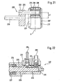
- the depository is in accordance with Fig. 23 formed so that it completely receives the cover surfaces of the slotted guide as the piston end, wherein the bearing has an axial extent which is greater than the stroke of the piston. This ensures that the cover surfaces of the slide guide is always in the storage area.
- crank pin can be rotatably mounted in a sliding block, wherein this is arranged transversely to the direction of movement of the piston in a connecting member connected to the piston guide.
- crank pin in a sliding block with hole ensures on the one hand a relatively strong and large-scale connection of the moving crank pin with another component.
- high surface pressure of the crank pin is opposite reduced to another component.
- slide guide and sliding block surface pressure to the piston is considerably reduced due to the very large compared to a crank pin area, which has a positive effect on the life of the components in question.
- loads of other components, in particular those of the bearing points of the piston and the seal are reduced.
- the motor power can be reduced, which reduces the power consumption of the pump, or it can be used a smaller motor.
- the reduced load also allows the formation of the crank pin with a smaller diameter, which also contributes to the reduction of friction.
- the flat support allows greater power transmission, so that such a designed pump can be designed for higher pressures.
- sliding block and link guide consist of a material pairing low friction.
- a further reduction in the surface pressures is achieved in that the piston is connected gimbal with the crank pin.
- a gimbal or cardan-like arrangement is achieved structurally particularly simple if the sliding block has a cylindrical cross-section and the slotted guide formed as a hole with a corresponding cross section in a piston-fixed part and thus the sliding block is rotatably mounted about its longitudinal axis. This flexibility allows the compensation of movement about an axis.
- Another important advantage of the cylindrical sliding block is that the entire lateral surface of the sliding block is in contact with the slotted guide. This embodiment is characterized by an extremely low surface pressure. The components have a long service life due to the low specific loads.
- crank pin and the slotted guide Additional friction between the crank pin and the slotted guide is avoided if in the wall of the slotted guide a slot for passage of the crank pin is formed, which has a greater width than the diameter of the crank pin. With a slot designed in this way undesired friction is avoided, in particular in the case of a crank pin which is skewed.
- crank pin To further reduce the friction between the crank pin and sliding block, it contributes, when the crank pin is rotatably mounted in the sliding block in a bearing which is inserted into a bore of the sliding block.
- the bearing is preferably designed as a plain bearing.
- the friction can be further reduced.
- plastics are particularly advantageous if the requirements are not too high. Plastics have good sliding and emergency running properties and are characterized by good lubrication.
- the eccentric drive or crank mechanism may have a drive shaft and the eccentricity of the crank pin to the drive shaft of the eccentric drive be adjustable. This configuration allows a switching of the crank pin to another eccentricity with which a different piston stroke can be realized. This allows operating the pump in two modes.
- the pump inlet and / or the pump outlet may be arranged axially to the longitudinal extent of the pump chamber.
- the pump inlet and / or the pump outlet are arranged radially to the pump chamber, wherein they can be arranged radially adjacent to each other.
- Pump inlet and pump outlet can also be arranged axially one behind the other.
- the seal may be arranged radially surrounding the piston between the bearing points of the piston.
- the seal is subjected to particularly low loads when it is arranged centrally between the bearings.
- the seal is loaded only slightly radially by tilting moments.
- a further reduction of the entry of wear particles from the bearing points is achieved if the piston has a larger or smaller diameter in the area between the bearing points than in the area of the bearing points.
- the seal is fixedly arranged in the pump housing and has a sealing lip, which is radially sealingly on the piston in sealing engagement.
- the piston can be dimensioned with a smaller diameter. This allows a reduction in the required installation space and the oscillating masses.
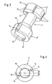
- spray nozzle 1 consists of a nozzle body 2, which is connected to a nozzle attachment 3 by means of a screw 4.
- a liquid channels 5 is arranged for the cleaning liquid.
- the pressure piece 7 is radially enlarged pot-shaped at its two ends. With the first cup-shaped part 8, the pressure piece 7 sits on a nozzle plate 9. The second pot-shaped part 10 surrounds the region in which the liquid channel 5 opens into the chamber 6.
- the second cup-shaped part 10 has four evenly distributed axial slots 11, can be flowed through the cleaning liquid supplied in the liquid channel 5 in the chamber 6.
- the first pot-shaped part 8 has two axially formed on the circumference of the pressure piece 7 grooves 12. In the region of the grooves 12, the cup-shaped part 8 is surrounded by a ring 13. This made of polyamide ring 13 seals the circumference of the cup-shaped part 8, so that the grooves 12 act as channels. At the lower end of the grooves 12 are radially extending, formed as slots channels 14, which extend approximately tangentially into a vortex chamber 15.
- the vortex chamber 15 is formed by the interior of the first cup-shaped part 8 and the nozzle plate 9. At the same time, the nozzle plate 9 closes an opening 16 in the nozzle attachment 3.
- the nozzle plate 9 in turn has a passage 17 through which the cleaning fluid exits the vortex chamber 15.
- FIG. 2 the passage 17 of the nozzle plate 9 is shown enlarged.
- the passage consists of a bore 18 which forms the outlet from the vortex chamber 15.
- the bore 18 has a diameter of, for example, 0.15 mm and a length of, for example, 0.11 mm.
- the hollow cone 19 has an opening angle of e.g. 30 ° at a length of e.g. 0.35 mm.
- the cleaning fluid which is set in rotation in the vortex chamber 15 by the approximately tangential passages 14, is greatly accelerated in the vortex due to the small diameter of the bore 18.
- the cleaning liquid then enters the hollow cone 19.
- the cleaning liquid is formed as a uniformly distributed thin film on the wall of the hollow cone 19 due to the swirling motion and the decompression.
- the film rotates about the axis A at high speed.
- the film breaks into a plurality of drops having an average size of about 10 ⁇ m and moving at a speed of about 50 m / s.
- the drops in their entirety form a hollow cone.
- the pressure piece 7 in FIG. 3 shows the two pot-shaped parts 8, 10.
- the second cup-shaped part 10 is divided by four evenly distributed around the circumference slots 11 in four areas. Due to their shape, these areas act as spring arms 21.
- the spring arms 21 are supported on the nozzle body 2, so that the first cup-shaped part 8 is pressed with the surface 22 against the nozzle plate 9.
- the two grooves 12 are arranged. Each of the grooves 12 is followed by a channel 14, approximately tangentially opening directly into the vortex chamber 15. Via the grooves 12 and the channels 14, the cleaning liquid flows from the chamber 6 to the vortex chamber 15th
- the location of the channels 14 to the vortex chamber 15 is the FIG. 4 removable.
- the channels 14 do not lead from the grooves 12 radially to the center, but run in opposite directions parallel to each other and enter the vortex chamber 15 with a center offset X.
- the center offset is chosen so that an undisturbed entering the vortex chamber 15 jet impinges on the wall of the vortex chamber at an angle of less than 45 ° and is redirected at the wall in a circulating flow.
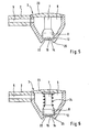
- FIGS. 5 and 6 show a second embodiment of the spray nozzle 1.
- the nozzle body 2 is not radially with respect to the axis of symmetry of the nozzle attachment 3, but preferably arranged approximately tangentially to the nozzle attachment 3.
- the liquid channel opens 5 also laterally into the chamber 6.
- the chamber 6 is closed by a lid 23.
- the pressure piece 7 is simplified in that no second cup-shaped part is necessary.
- the vortex chamber 15 is in turn arranged in the first cup-shaped part 8.
- the pressure piece 7 is supported on the cover 23, so that the surface 22 rests sealingly on the nozzle attachment 3.
- the sealing effect of the surface 22 is supported by a spring 24 which presses the pressure piece 7 against the nozzle attachment 3.
- the cleaning liquid in turn enters the vortex chamber 15.
- FIG. 1 own the spray nozzles 1 in FIGS. 5 and 6 no nozzle plate.
- the bore 18 and the hollow cone 19 are arranged in the nozzle attachment 3.
- several projections 25 are present around the outgoing jet.
- the projections 25 have an axial extent of about 3 mm. The projections 25 are used to set an optimal working distance by the spray nozzle 1 is placed with the projections 25 on the areas to be cleaned.
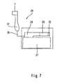
- the device 26 in FIG. 7 comprises a liquid container 27 which can be filled by the user with cleaning liquid. From this liquid container 27, the cleaning liquid is conveyed by means of a pump 28, which is driven by an electric motor 29, via a hose 30 to a handpiece 31. On the handpiece 31, the spray nozzle 1 is arranged replaceably. On the electric motor 29, a sensor 32 is arranged, which measures the torque generated by the electric motor 29 and then provides a signal to the pump 28 so that it can be operated in the operating mode corresponding to the spray nozzle used.
- the pump 28 If the spray nozzle 1 according to the invention is used, then the pump 28 generates a volume flow of 50 ml / min at approximately 40 bar in the high-pressure mode. This corresponds approximately to a mechanical or hydraulic power of about 2000 ml / min bar or about 3.3 W. If a conventional spray nozzle arranged on the handpiece 31, the sensor 32 detects the opposite of the spray nozzle 1 according to the invention changed torque and the pump 28 is operated in the oral shower mode. The pump 28 delivers a volume flow of about 300 ml / min with a pressure of 6 bar. This results in a mechanical or hydraulic power of about 1800 ml / min bar or 3.0 W. Due to the approximately same mechanical performance in both modes of operation, the device 26 with a pump 28 and an electric motor 29 is operable.
- the eccentric drive described below has at least two different movements on the output.
- the different movements on the output are adjustable with minimal effort.
- the adjustment is also possible without an external intervention in the drive.
- the space of the eccentric drive is not significantly larger.
- the eccentric 101 in FIG. 8 has a drive element 102, which is designed as a drive shaft and is mounted in two bearing points 103, 104. At one end of the drive shaft, a spur gear 105 is fixed. The spur gear 105 is connected to a drive device, not shown, and serves to drive the drive shaft. A disk-shaped region 116 for receiving a disk 106 is integrated in the spur gear 105.
- the spur gear 105 has a bore 107 arranged with an eccentricity e1.
- the disk 106 is rotatably mounted in the bore 107.
- the disk 106 has a bore 109 arranged with an eccentricity e2, in which a crank pin 110 serving as an output is inserted. At the crank pin 110 engages a connecting rod 111, which drives the piston, not shown, of a pump.
- the disk 106 has a groove 112 into which engages a pin 113 formed as a pin, which is fixed in the spur gear 105.
- the disk 106 and the crankpin 110 are arranged such that the eccentricities of the disk e1 and the crankpin e2 are aligned in a line. In this position, the eccentricities e1 and e2 add up to the largest overall eccentric dimension e3.
- the crank pin 110 transmits to the connecting rod 111 a stroke corresponding to the double eccentric total dimension e3.
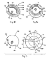
- FIG. 9 shows the spur gear 105 with the eccentrically arranged thereon disc 106 and the eccentric to the disc 106 arranged crank pin 110.
- the circular arc-shaped groove 112 of the disc 106 engages the driver 105 attached to the spur gear 105 a.
- the groove 112 extends over 180 °.
- the ends 114, 115 form the stops for the driver 113.
- the largest Exzentergefelinate e3 adjusts itself when the spur gear 105 is driven in the direction of rotation shown.
- the follower 113 runs in the groove 112 of the disc 106 until it stops 114. If the driver 113 abuts against the stop 114, it rotates the disc 106 and thus the crank pin 110 with the spur gear 105 in the direction of rotation shown.
- FIGS. 10 and 11 show a changed position of the crank mechanism 101 after FIGS. 8 and 9 wherein the spur gear 105 is driven in the opposite direction of rotation.
- the drive shaft has at its end facing the disk 106 a disk-shaped region 116, which is designed to receive the disk 106.
- the spur gear 105 is arranged.
- the connecting rod 111 When switching in the illustrated direction of rotation, the connecting rod 111 counteracts a braking torque, so that the crank pin 110 and thus the disc 106 remain in their position.
- the arranged in the spur gear 5 driver 13 now runs from the stop 114 in the groove 112 to stop 115, so that the spur gear 105 relative to the disc 106 rotated by 180 °.
- the disk 106 is carried along by the driver 113.
- the spur gear 105 and the disc 106 rotate again at the same speed.
- the crank mechanism 101 in FIG. 12 shows one opposite FIG. 8 slightly modified eccentric drive 101, wherein the sprocket of the spur gear 105 is shown as a dashed line.
- the spur gear 105 has two symmetrically arranged drivers 113, which run in two concentrically arranged circular-arc grooves 112 of the disk 106. The ends of the grooves 114, 115 form the stops for the drivers 113.
- the eccentric drive 101 shown in Figure 106 has a spur gear 105, the sprocket is shown as a dashed line.
- the spur gear 105 has a plurality of bores 117, 117 ', 117 ". These bores 117, 117', 117" serve to receive the disk 106, wherein the bores 117, 117 ', 117 "have different eccentricities e1, e1', e1" ,
- the spur gear 105 can thus be used for various requirements by mounting the disc 106 in the corresponding bore 117, 117 ', 117 " 117, 117 ', 117 "corresponding holes 118, 118', 118" assigned, in which the driver 113 is arranged.
- the disc 106 in turn has stops 114 ', 115', which are not arranged in the disc 106 as grooves 112, but as regions 119 with a larger radius at the periphery of the disc 106.
- the disk 106 according to FIG. 14 has two concentrically arranged grooves 112, in which two drivers 113 run. At the ends of the grooves 112 each have a coil spring 120 is arranged so that, depending on the direction of rotation of the drive shaft, each driver 113 rests against a coil spring 120 and the disc 106 rotates at the speed of the drive shaft. The coil springs 120 cause the drivers 113 do not rest completely at the end of the respective groove 112. As a result, the crank pin 110 is no longer in line with the center of the disc 106 and the drive shaft, and the eccentricity e1 only adds up in part to the eccentricity e1 of the disc 106. The resulting maximum eccentric dimension e3 is thus smaller. In addition, shocks are damped when switching the direction of rotation.
- the coil springs 120 are designed with respect to their spring characteristic so that even small changes in the torque generated by the drive means are sufficient to change over the torque transmitting carrier 113 the spring travel. With changes in the spring travel, the disk 106 rotates to the drive shaft, which leads to slight changes in the position of the crank pin 110 and thus the Exzentergefel dealtes e3, e4. In this way, a fine adjustment of the Exzentergelogie proceedingses e3, e4 and thus the hub of the connecting rod can be done by a torque control on the drive device or the drive shaft.
- the spur gear 105 and the drive shaft is integrally formed as a drive element 102.
- the drive shaft is rotatably mounted in the bearing points 103, 104.
- the drive shaft has a bore 121 in which a crankshaft 122 is mounted.
- the crankshaft 122 is arranged with an eccentricity e1 in the drive shaft.
- the crank pin 110 which is connected via a crank arm 123 to the crankshaft 122, has an eccentricity e2 relative to the crankshaft 122.
- the connecting rod 111 is attached.
- crankshaft 122 is arranged such that the crankpin 110 is oriented radially outward with respect to the bearing of the crankshaft 122.
- the eccentricities e1, e2 of the crankshaft 122 and the crank pin 110 add up to the largest Exzentergefelinate e3.
- the crank pin 110 transmits to the connecting rod 111 a stroke corresponding to the double eccentric total dimension e3.
- the drive element 102 is driven via the spur gear 105 in the rotational direction shown by the drive device, not shown.
- An integrally formed on the drive member 102 driver 113 is arranged so that it the crankshaft 122 in the in FIG. 15 takes shown position.
- FIGS. 110 and 111 show the arrangement of the eccentric drive 101 FIGS. 15 and 16 wherein the spur gear 105 is driven in the opposite direction of rotation.
- the crankpin 110 is disposed radially inwardly with respect to the bearing of the crankshaft 122, so that its eccentricity e2 is now aligned against the eccentricity e1 of the crankshaft 122.
- the crank pin 110 transmits to the connecting rod 111 a stroke which corresponds to twice the smallest eccentric total dimension e4.
- cranking operation is not only applicable to oral irrigators, but can also be used in other fields, for example in pumping devices in general or in devices in which a conversion of a rotational movement is to be achieved in a translational movement.
- the oral irrigator has a plunger pump. This has an improved efficiency over known oral shower pumps.
- the plunger pump should have as low-wear as possible drive for the piston.
- the life of the piston and the seal should be increased.
- the plunger pump 201 in FIG. 19 has a pump housing 202 having an axially disposed pump inlet 203 and a radially disposed pump outlet 204. At the opposite end of the plunger pump 201, a piston 205 penetrates the pump housing 202. The piston 205 is driven by an eccentric drive 206 or crank mechanism. The piston 205 has a slotted guide 207, which receives a sliding block 208. To move the piston 205, a drive shaft 209 of the eccentric drive 206 or crank drive is set in rotation by an electric motor, not shown.
- the internal structure of the plunger pump 201 with the pump chamber 210 is in FIG. 20 shown.
- the pump chamber 210 has with the pump inlet 203 and the pump outlet 204 two ports, each associated with a check valve 211.
- the one or more check valves 211 may be spring-loaded.
- the check valves 211 are aligned so that upon movement of the piston 205 from the pump chamber 210, the check valve 11 opens in the pump inlet 203, while the check valve 211 is closed in the pump outlet 204.
- liquid is sucked from a container, not shown, in the oral irrigator via the pump inlet 203 into the pumping chamber 210.
- the behavior of the check valves 211 revolves, and the liquid is delivered via the pump outlet 204 to a handpiece, not shown, of the irrigator.
- the piston 205 is mounted in two bearing points 212, 213, which are located in the pump housing 202. In addition to its axial mobility, the piston 205 is rotatable about its longitudinal axis H.
- the bearing 212 on the pump chamber 210 is designed so that the piston end 214 is guided at a stroke between the top and bottom dead center.
- the bearing 213 is located at the other end of the pump housing 202.
- a seal 215 is fixedly arranged in the pump housing 202.
- a sealing lip 216 in this case seals off the piston 205.
- the slotted guide 207 is arranged on the other end of the piston 205.
- the slide guide 207 has a bore 217, in which the cylindrical sliding block 208 is arranged.
- the scenery or the sliding block 208 is both axially movable and rotatable about the axis V. Due to the rotatable arrangement of the piston 205 and the link or the sliding block 208 about the axes H and V, the piston 205 is connected to a crank pin 220 of the eccentric 206 (or the crank pin 110 of the eccentric 101) virtually like gimbal connected, only with the Difference that the piston 205 rotates about the axis H instead of being pivoted about an axis which is perpendicular to both axes H and V.
- the piston 205 and this gimbal-like connection allow compensation of a skewed arrangement of the crankpin 220 due to tolerances or elastic and / or plastic or other deformations.
- a gimbal connection in the sense of this description arises when the piston 205 and the sliding block are rotatable or pivotable about respective different axes H, V, wherein both axes H and V are perpendicular to each other.
- the sliding block 208 has a transverse to the axis V bore 218, in which a bearing bush 219 is inserted.
- the bushing 219 is configured to receive the crankpin 220.
- the crank pin 220 For receiving in the sliding block 208, the crank pin 220 must penetrate the slotted guide 207.
- the slide guide 207 has a slot 221.
- the width of the slot 221 is greater than the pin diameter. In this way, a contact of the crank pin 220 with the slotted guide 207 is excluded. The width is chosen so that there is no contact even with a space skewed crank pin 220.
- crank pin 220 moves in a circular path.
- the crank pin 220 and the sliding block 208 are at top dead center.
- the piston 205 is located exactly in the middle between its two reversal points, which limit its stroke.
- the sliding block 208 moves in the slotted guide 207 during the first half turn down.
- the piston 205 reaches after a quarter turn of the crank pin 220 its rear reversal point, which ends the suction process.
- the check valve 211 is opened in the pump inlet 203, while the other check valve 211 is closed.
- piston 205 again moves toward pumping chamber 210.
- the check valve 211 in the pump inlet 203 is closed while the check valve 211 in the pump outlet 204 is opened.
- the crank pin 220 mounted in the sliding block 208 reaches the bottom dead center.
- the piston 205 is in the position shown.
- the sliding block 208 is again moved upwards, with the piston 205, after halfway through this movement, reaching its front reversing point, which ends the exhausting operation. It remains to mention that in Fig. 20 Springs for biasing the check valves 211 are not shown.
- FIG. 21 shows the crank mechanism 206 with the slotted guide 207 of the piston 205.
- the crank mechanism 206 has a drive shaft 209, on which a disc 222 is fixed.
- the disk 222 carries the crank pin 220 arranged with the eccentricity E1.
- the crank pin 220 extends through the slot 221 of the guide slot 207 into the sliding block 208, where it is received in a bearing bush 219.
- the plunger pump 201 of a second embodiment in FIG. 22 shows the arrangement of the pump outlet 204 behind the pump inlet 203, wherein both ports are arranged radially on the circumference of the plunger pump 201.
- the terminals 203, 204 are integrated in a pressure piece 223, which is mounted on the plunger pump 201.
- the piston 205 has at its pump inlet 203 and the pump outlet 204 side facing a flattening 224.
- the flattening 224 ensures a connection of the pump outlet 204 with the pump chamber 210, which is independent of the position of the piston 205.
- both check valves 211 are each loaded with a spring or biased.
- the piston 205 has three regions with different diameters 225-227, which become larger from the bearing 212 over the region of the seal 215 up to the bearing point 213, which is no longer shown. With these steps 225-227 of the piston diameter, a distribution of resulting wear particles is avoided in the areas of the seal or bearings.
- Such a pump is not only usable every oral showers, but can also be used in other areas, such as irrigation systems. In principle, it can be used with all pump devices with piston guide.
- the oral irrigator preferably has two functions (operating modes) or two different, optionally usable spray nozzles.
- the speed of the exiting cleaning liquid is low (this speed is preferably below 20 m / s, in particular from 10 m / s to 15 m / s).
- the flow in this oral shower function is at least 100 ml / min, in particular 200 ml / min to 400 ml / min, preferably about 300 ml / min.
- the other high-pressure function has already been described in detail.
- the different functions are made possible by the switching center or two different long stroke paths of the pump.
- One of the two functions can be set optionally.
- One function is practically an oral shower function, the other a new special function for plaque removal, which is similar to the brushing with a toothbrush or has a comparable cleaning effect. This special function can at least reduce the use of a toothbrush and thus avoid heavy abrasion.
- the special function can also be present in a stand-alone device without oral shower function. It is also conceivable a station with two such different oral showers, i. a low pressure irrigator (as a device) and a high pressure irrigator as another device, both devices being able to use the same or different pumps.
- a high-pressure piston pump is preferably provided which preferably reaches a maximum of about 50 to 70 bar, in particular about 60 bar. Also possible is one of the pressure ranges described above.
- the flow rate is preferably about 50 to 70 ml / min, in particular 60 ml / min.
- the working distance between tooth and nozzle outlet is about 2 - 6 mm.
- Such a system with two functions enables a particularly effective dental care. While the actual oral irrigator frees the teeth from coarse particles and the gums are perfused, the subsequent cleaning with the high-pressure spray nozzle ensures thorough cleaning of the teeth.
- the system may also include an electric toothbrush.
- the FIG. 25 again illustrates the spray function or the special spray nozzle.
- the arrow 300 illustrates the eccentrically arranged slots that create the water vortex.
- the arrow 301 points to the vortex chamber with rotating water.
- the arrow 302 points to the rotating water, which forms a thin film of water along the conical nozzle exit.
- the water film (arrow 303) changes into micro-fine drops at the exit.
- the drop size can be changed by the slot geometry and / or the slot spacing to the center of the vortex chamber and / or by the angle and / or length of the exit cone.
- Fig. 26 shows a tooth division according to "Rustogi".
- the oral irrigator according to the invention more than 70% to 80% of the plaque is removed after only 2 min / teeth cleaning time in the aproximal areas (D and F) and in the gingival areas (A, B and C). In the other areas (I, G, H and E) even a better cleaning effect is given. A cleaning is also given in the proximal areas (tooth gaps).
- a very abrasionsarme or tooth-friendly cleaning is given.
- FIGS. 27 to 29 show the cleaning process by means of a microfine droplet 310.
- This impulse strikes impulsively with high energy on a plaque layer 311 via a tooth 312 (FIG. Fig. 27 ).
- This energy pushes the plaque outward ( Fig. 28 ), wherein in the drop center, a high pressure is present. It creates a crater.
- the pressure shifts outward, like the two upward arrows of the Fig. 29 illustrate.
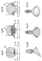
- FIGS. 30 to 32 show further embodiments of the spray nozzle, which can be combined with the features of one or more of the nozzles described above.
- Fig. 30 creates a shallow beam that expands.
- Fig. 31 shows a spray nozzle with a solid cone steel.
- Fig. 32 shows a spray nozzle with a hollow cone jet, With a very gentle cleaning effect can be achieved, the volume of water is low.
- a spray nozzle with a nozzle attachment which is preferably designed as a brush ring 320 - preferably with a plastic ring 321 and sectorally arranged brush hairs 322 -.
- This can be arranged fixed or detachable on the nozzle head.
- the brush ring has in addition to an increase in the cleaning effect nor the additional effect of a spacer, so that there is a fixed (safety) distance between the tooth and the nozzle opening.
- As a spacer can also serve a busless element.
- the brush-type nozzle attachment can also be used for a known low-pressure oral irrigator.
- the invention is not limited only to the examples described. Any combination of the individual features of different examples is possible. In particular, the combination of an oral irrigator after the FIGS. 1 to 7 with an eccentric drive according to the FIGS. 8 to 18 and / or with a pump according to the FIGS. 19 to 24 appropriate.
Abstract
Description
Gegenstand der Erfindung ist eine Munddusche, eine Sprühdüse sowie ein Zahnreinigungssystem nach dem Oberbegriff der unabhängigen Ansprüche.The invention relates to an oral irrigator, a spray nozzle and a tooth cleaning system according to the preamble of the independent claims.
Es ist bekannt, die Reinigungswirkung von Mundduschen zu verbessern, indem spezielle Sprühdüsen zur Erzeugung von Flüssigkeitsstrahlen bestimmter Ausbildung verwendet werden. Unter Sprühdüse im Rahmen dieser Anmeldung kann auch eine Düse zur Abgabe eines nicht aus Einzeltropfen bestehenden Wasserstrahls verstanden werden. Aus der
Aus der
Aus der
Aus der
Aus der
Der vorliegenden Erfindung liegt daher die Aufgabe zugrunde, eine Munddusche und eine Sprühdüse für die Munddusche mit verbesserter Reinigungswirkung zu schaffen. Der Flüssigkeitsstrahl soll in der Lage sein, fest haftende Plaque im approximalen Bereich sowie am Zahnfleischsaum zu entfernen. Die Sprühdüse zur Erzeugung eines derartigen Flüssigkeitsstrahls soll möglichst verschleißfrei arbeiteten und einfach aufgebaut sein. Überdies soll eine Vorrichtung für die Sprühdüse geschaffen werden, die eine umfassende Reinigung der Zähne und des Zahnfleisches ermöglicht.The present invention is therefore based on the object to provide an oral irrigator and a spray nozzle for the oral irrigator with improved cleaning effect. The fluid jet should be able to remove adherent plaque in the approximal area and the gingival margin. The spray nozzle for producing such a liquid jet should work as wear-free as possible and be simple. In addition, a device for the spray nozzle is to be created, which allows a comprehensive cleaning of the teeth and the gums.
Die Aufgabe wird durch die kennzeichnenden Merkmale der unabhängigen Ansprüche gelöst.The object is solved by the characterizing features of the independent claims.
Erfindungsgemäß wird die Reinigungsflüssigkeit einer Sprühdüse mit hohem Druck zugeführt, wobei von einem Düsenauslaß ein Flüssigkeitsstrahl austritt, der eine hohe Geschwindigkeit aufweist und aus mikrofeinen Tropfen besteht. Insbesondere wird von dem Düsenauslaß ein dünner, sich schnell bewegender Flüssigkeitsfilm gebildet, der dann in mikrofeine Tropfen mit hoher Geschwindigkeit übergeht.According to the invention, the cleaning liquid is fed to a spray nozzle at high pressure, wherein a liquid jet emerges from a nozzle outlet, which has a high velocity and consists of microfine droplets. In particular, a thin, rapidly moving liquid film is formed from the nozzle outlet, which then merges into microfine droplets at high speed.
Dadurch daß der Druck mindestens 15 bar beträgt und/oder das die Geschwindigkeit mindestens 23 m/s beträgt, wird eine Verbesserung der Reinigungswirkung gegenüber dem Stand der Technik erreicht.The fact that the pressure is at least 15 bar and / or that the speed is at least 23 m / s, an improvement of the cleaning effect over the prior art is achieved.
Ein hoher Druck von mindestens 15 bar reicht aus, um eine sichere Bildung der mikrofeinen Tropfen zu ermöglichen, wobei die Geschwindigkeit des Flüssigkeitsstrahls vorzugsweise höher als 25 m/s ist. Eine deutlich bessere Reinigungswirkung wird jedoch bei einem Druck von über 20 bar und/oder eine Geschwindigkeit von über 35 m/s erreicht.A high pressure of at least 15 bar is sufficient to allow a safe formation of the microfine droplets, wherein the velocity of the liquid jet is preferably higher than 25 m / s. However, a significantly better cleaning effect is achieved at a pressure of over 20 bar and / or a speed of over 35 m / s.
Durch die erfindungsgemäße Lösung kann der Einsatz eines Schabers oder eines anderen Zusatzteiles entfallen. Insbesondere wird die mikrofeine Tropfengröße als relativ angenehm empfunden. Grundsätzlich kann die Munddusche aber in Verbindung mit einem Bürstenteil oder einem anderen Zusatzteil, das die Zähne direkt berührt, gleichzeitig betrieben werden. Das Zusatzteil kann als ein konzentrisch um den Düsenauslaß angeordneter Bürstenkranz ausgebildet sein.The inventive solution eliminates the use of a scraper or other additional part. In particular, the microfine drop size is perceived as relatively pleasant. In principle, however, the oral irrigator can be operated simultaneously in conjunction with a brush part or another attachment that directly touches the teeth. The additional part may be formed as a brush ring arranged concentrically around the nozzle outlet.
Infolge der hohen Aufprallenergie der Tropfen auf der Plaqueschicht wird die Reinigungsflüssigkeit seitlich weggedrückt. Die dabei erzeugten Scherkräfte reißen die Plaqueoberfläche unter Gruben- und Kraterbildung auf. Da der Flüssigkeitsstrahl aus einer Vielzahl von Tropfen besteht, wiederholt sich dieser Vorgang in schneller Folge. Auf diese Weise wird die Plaqueschicht schichtweise abgetragen. Der Vorteil eines derart erzeugten, aus Tropfen bestehenden Flüssigkeitsstrahls besteht darin, daß nunmehr auch im approximalen Bereich und am Zahnfleischsaum haftende Plaque entfernt werden kann. Des weiteren ist aufgrund der mechanischen Entfernung der Plaqueschicht kein Zusatz für die Reinigungsflüssigkeit notwendig, so daß für die Plaqueentfernung Wasser als Reinigungsflüssigkeit verwendet werden kann.Due to the high impact energy of the drops on the plaque layer, the cleaning liquid is pushed away laterally. The shear forces generated thereby rupture the plaque surface under pit and crater formation. Since the liquid jet consists of a plurality of drops, this process is repeated in rapid succession. In this way, the plaque layer is removed layer by layer. The advantage of a liquid jet produced in this way consists in the fact that it is now also possible to remove plaque adhering in the approximal region and the gingival margin. Further, due to the mechanical removal of the plaque layer, no addition of the cleaning liquid is necessary, so that water can be used as a cleaning liquid for plaque removal.
Zur Erzeugung der Tropfen mit hoher Geschwindigkeit wird die Reinigungsflüssigkeit der Sprühdüse mit hohem Druck zugeführt. In Abhängigkeit der speziellen Ausgestaltung liegt der Druck über etwa 15 bar, insbesondere zwischen etwa 25 bar und 55 bar, wobei sich in einem Druckbereich von 35 bar bis 45 bar die besten Reinigungsergebnisse erzielen lassen.To generate the drops at high speed, the cleaning liquid is supplied to the spray nozzle at high pressure. Depending on the specific embodiment, the pressure is above about 15 bar, in particular between about 25 bar and 55 bar, which can be achieved in a pressure range of 35 bar to 45 bar, the best cleaning results.
Zur Erzeugung der Tropfen muß die Reinigungsflüssigkeit zerstäubt oder versprüht werden. Besonders kleine Tropfen lassen sich bei gleichen Düsendurchmessern und Drücken erzeugen, wenn der Flüssigkeitsstrahl als divergierender Hohlkegelstrahl ausgebildet wird. Der divergierende Hohlkegelstrahl hat zudem den Vorteil, daß die Sprühfläche mit wachsendem Abstand vom Düsenauslaß vergrößert wird, was eine schnellere Reinigung ermöglicht. Neben dem Hohlkegelstrahl ist aber auch die Erzeugung eines Vollkegel- oder Flachstrahls denkbar.To generate the drops, the cleaning liquid must be atomized or sprayed. Particularly small drops can be produced at the same nozzle diameters and pressures, if the liquid jet is formed as a diverging hollow cone jet. The diverging hollow cone jet also has the advantage that the spray area is increased with increasing distance from the nozzle outlet, allowing faster cleaning. In addition to the hollow cone beam but also the generation of a full cone or flat jet is conceivable.
Neben der Strahlform ist die Bildung des Strahls bestimmend für die Ausbildung der mikrofeinen Tropfen. Diese lassen sich dadurch erzeugen, daß die Reinigungsflüssigkeit im Düsenauslaß als dünner Film gebildet wird, der gleichmäßig an der Innenwand des Düsenauslasses verteilt ist. Beim Verlassen des Düsenauslasses zerreißt dieser gleichmäßig verteilte Film kurz hinter dem Düsenauslaß in die mikrofeinen Tropfen.In addition to the beam shape, the formation of the jet is decisive for the formation of the microfine droplets. These can be produced by the cleaning liquid is formed in the nozzle outlet as a thin film, which is evenly distributed on the inner wall of the nozzle outlet. When leaving the nozzle outlet, this evenly distributed film tears into the microfine droplets just behind the nozzle outlet.
Haftende Plaqueschichten lassen sich besonders gut mit einem aus Tropfen bestehenden Flüssigkeitsstrahl abtragen, dessen Tropfen eine Größe von etwa 5 µm bis 10 µm und eine Geschwindigkeit von mindestens 23m/s, vorzugsweise etwa 45 m/s bis 55 m/s besitzen.Adhesive plaque layers can be removed particularly well with a liquid jet consisting of droplets whose droplets have a size of about 5 μm to 10 μm and a speed of at least 23 m / s, preferably about 45 m / s to 55 m / s.
Von Vorteil ist bezüglich einer Sprühdüse zur Erzeugung eines Flüssigkeitsstrahls für eine Munddusche, mit einem Düsenkörper, der eine Kammer aufweist, in die ein Flüssigkeitskanal zur Zufuhr von unter Druck stehender Reinigungsflüssigkeit mündet und von der ein Düsenauslaß zum Austreten eines Reinigungsflüssigkeitsstrahls ausgeht, daß die Kammer mit einer Wirbelkammer etwa runden Querschnitts zum Erzeugen eines umlaufenden Stroms der Reinigungsflüssigkeit verbunden ist, von der zentrisch der Düsenauslaß ausgeht, der aus einer bevorzugt etwa zylindrischen Engstelle und einer optional sich daran anschließenden insbesondere etwa kegelartigen Erweiterung besteht. Gegebenenfalls kann die Erweiterung auch weggelassen werden oder nicht keglig ausgebildet sein.It is advantageous with respect to a spray nozzle for producing a liquid jet for an oral irrigator, with a nozzle body having a chamber into which a liquid channel for supplying pressurized cleaning liquid opens and from which a nozzle outlet for the discharge of a cleaning liquid jet emanates that the chamber is connected to a swirl chamber approximately circular cross-section for generating a circulating stream of cleaning liquid, from the center of the nozzle outlet emanating from a preferably about cylindrical constriction and an optional adjoining in particular approximately conical extension exists. Optionally, the extension can also be omitted or not keglig trained.
Diese Gestaltung ermöglicht es, einen Flüssigkeitsstrahl, bestehend aus mikrofeinen Tropfen hoher Geschwindigkeit, zu erzeugen, der aufgrund der Tropfengeschwindigkeit in der Lage ist, Plaque zu entfernen. Eine mit der als Hohlkegeldüse ausgebildete Sprühdüse durchgeführte Reinigung ermöglicht bei gleicher Nutzungsdauer aufgrund einer deutlich geringeren Abrasion der Epithelzellschicht eine schonendere Reinigung als mit einer elektrischen Zahnbürste. Weiterhin ermöglicht die Sprühdüse nach der Verwendung einer elektrischen Zahnbürste insbesondere im approximalen Bereich eine zusätzliche Reduzierung von ca. 60 % Plaque. Die Sprühdüse kommt ohne sich bewegende Bauteile aus, die einem verstärkten Verschleiß unterliegen würden.This design makes it possible to produce a liquid jet consisting of microfine drops of high speed, which due to the drop velocity is able to remove plaque. A cleaning performed with the spray nozzle designed as a hollow nozzle allows for the same service life due to a significantly lower abrasion of the epithelial cell layer a gentler cleaning than with an electric toothbrush. Furthermore, the spray nozzle allows for the use of an electric toothbrush, especially in the approximal region, an additional reduction of about 60% plaque. The spray nozzle eliminates moving parts that would be subject to increased wear.
Für die Erzeugung der mikrofeinen Tropfen mit hoher Geschwindigkeit hat sich eine Engstelle in Form einer Bohrung mit einem Durchmesser von etwa 0,1 mm bis 0,2 mm und einer Tiefe von etwa 0,05 mm bis 0,2 mm als vorteilhaft herausgestellt. Eine derart ausgebildete Engstelle gewährleistet, daß die aus der Wirbelkammer austretende Reinigungsflüssigkeit mit einem hohem Druck und hoher Geschwindigkeit in die optional nachfolgende Erweiterung eintritt.For the production of microfine drops at high speed, a constriction in the form of a hole with a diameter of about 0.1 mm to 0.2 mm and a depth of about 0.05 mm to 0.2 mm has been found to be advantageous. Such a bottleneck ensures that the exiting from the vortex chamber cleaning fluid enters at a high pressure and high speed in the optional subsequent expansion.
Um schließlich den aus vielen Tropfen bestehenden Flüssigkeitsstrahl zu bilden, hat sich eine Erweiterung, insbesondere in Form eines Kegels oder Hohlkegels als günstig erwiesen, wobei die Erweiterung sich der Engstelle anschließt. Mit diesem Zerstäubungsprinzip lassen sich besonders feine Tropfen erzeugen. Nach dem Passieren der Engstelle legt sich Reinigungsflüssigkeit an die Wandung des Hohlkegels als gleichmäßig verteilter dünner Film an, wobei dieser Film aufgrund der Wirbelkammer um die Symmetrieachse der Erweiterung rotiert. Aufgrund der hohen Tangentialgeschwindigkeit zerreißt der Film in die mikrofeinen Tropfen, sobald er den Hohlkegel verläßt, insbesondere kurz hinter dem Düsenaustritt. Für eine optimale Ausbildung der Tropfen hat sich ein Kegel oder Hohlkegel mit einer Länge von etwa 0,2 mm bis 0,5 mm und einem Öffnungswinkel von etwa 20° bis 70° erwiesen. Diese Düsengeometrie zeichnet sich überdies dadurch aus, daß auch bei hohen Tropfengeschwindigkeiten kleine Volumenströme, z.B. von weniger als 80 ml/min, möglich sind, ohne daß die Düsengeometrie so klein wird, daß die Kosten für die Herstellung steigen. Auf diese Weise werden extrem kleine Düsengeometrien, die zudem eine kürzere Lebensdauer besitzen, vermieden. Die als Hohlkegel ausgebildete Düse besitzt zudem den Vorteil, daß sie auch bei Fertigungsungenauigkeiten oder Verunreinigungen ein sehr stabiles Strahlbild aufweist.Finally, in order to form the liquid jet consisting of many drops, an enlargement, in particular in the form of a cone or hollow cone, has proved to be favorable, wherein the extension adjoins the constriction. With this atomization principle, it is possible to produce particularly fine drops. After passing through the constriction, cleaning liquid is applied to the wall of the hollow cone as evenly distributed thin film, this film rotates due to the vortex chamber about the axis of symmetry of the extension. Due to the high tangential velocity, the film breaks into the microfine droplets as soon as it leaves the hollow cone, in particular shortly after the nozzle exit. For optimal formation of the drops, a cone or hollow cone with a length of about 0.2 mm to 0.5 mm and an opening angle of about 20 ° to 70 ° has been found. This nozzle geometry is also characterized by the fact that even at high drop speeds small volume flows, for example of less than 80 ml / min, are possible without the nozzle geometry is so small that the cost of production increase. In this way, extremely small nozzle geometries, which also have a shorter life, avoided. The designed as a hollow cone nozzle also has the advantage that it has a very stable spray pattern even in manufacturing inaccuracies or impurities.
Es ist aber auch denkbar, anstelle der Hohlkegeldüse eine Flachstrahldüse oder Vollkegeldüse zu verwenden.However, it is also conceivable to use a flat jet nozzle or full cone nozzle instead of the hollow cone nozzle.
Der Auslaß läßt sich kompakt und somit platzsparend aufbauen, wenn er in einem an dem Düsenkörper angeordneten Düsenaufsatz ausgebildet ist.The outlet can be compact and thus save space when it is formed in a arranged on the nozzle body nozzle attachment.
Zu einer weiteren Vereinfachung in der Herstellung des Düsenaufsatzes trägt es bei, wenn die Engstelle und die Erweiterung in einem separaten Bauteil, z.B. einer Düsenplatte, angeordnet sind. Die Montage der Düsenplatte im Düsenaufsatz ist nur mit einem geringen Mehraufwand verbunden, während die Fertigung in Bezug auf Genauigkeit, Maßhaltigkeit und Kosten mit einer Düsenplatte günstiger ist. Zudem kann die Düsenplatte aus einem anderen, verschleißbeständigerem Material bestehen.A further simplification in the manufacture of the nozzle attachment is achieved if the constriction and the extension in a separate component, e.g. a nozzle plate are arranged. The assembly of the nozzle plate in the nozzle attachment is associated with only a small overhead, while the production is cheaper in terms of accuracy, dimensional stability and cost with a nozzle plate. In addition, the nozzle plate made of a different, wear-resistant material.
Der Düsenaufsatz gewährleistet eine Auswechselbarkeit, wenn er mittels einer lösbaren Verbindung mit dem Düsenkörper verbunden ist. Die lösbare Verbindung kann entweder als Schraubverbindung oder als Rast- und Steckverbindung ausgebildet sein. Dadurch läßt sich der Düsenaufsatz beispielsweise bei Beschädigungen auswechseln. Gleichzeitig ermöglicht ein derartig ausgebildeter Düsenkörper die Aufnahme herkömmlicher Düsenaufsätze, die mit einem wesentlich größeren Volumenstrom bei erheblich niedrigerem Druck betrieben werden.The nozzle attachment ensures interchangeability when it is connected to the nozzle body by means of a detachable connection. The detachable connection can be designed either as a screw connection or as a latching and plug connection. As a result, the nozzle attachment can be replaced, for example, in case of damage. At the same time, a nozzle body designed in this way allows the inclusion of conventional nozzle attachments, which are operated at a considerably greater volume flow at a considerably lower pressure.
Für die Gestaltung der Wirbelkammer hat sich die Anordnung eines Druckstücks in der Sprühdüse als vorteilhaft erwiesen. Das Druckstück ist in einer Kammer angeordnet, die zwischen dem Düsenaufsatz und dem Düsenkörper gebildet ist. Zur Fixierung des Druckstücks in der Kammer ist der im Düsenkörper oder Düsenaufsatz befindliche Teil des Druckstücks mit einer Preßpassung eingesetzt oder mittels am Düsenaufsatz oder Düsenkörper angeordneten Rastelementen fixiert. Diese Fixierung erleichtert zum einen die Montage und zum anderen ist das Druckstück bei einem Wechsel des Düsenaufsatzes unverlierbar mit einem der beiden Teile verbunden. Es ist aber auch denkbar, das Druckstück aufgrund eines Übermaßes oder mittels einer Feder zwischen Düsenkörper und Düsenaufsatz einzuspannen.For the design of the vortex chamber, the arrangement of a pressure piece in the spray nozzle has proven to be advantageous. The pressure piece is arranged in a chamber which is formed between the nozzle attachment and the nozzle body. For fixing the pressure piece in the chamber located in the nozzle body or nozzle attachment part of the pressure piece is inserted with a press fit or fixed by means arranged on the nozzle attachment or nozzle body locking elements. This fixation facilitates on the one hand the mounting and on the other hand, the pressure piece is captively connected to one of the two parts at a change of the nozzle attachment. But it is also conceivable, the pressure piece due to a To clamp excess or by means of a spring between the nozzle body and nozzle attachment.
Das Druckstück kann an seinen beiden Enden je ein topfförmiges Teil aufweisen. Das erste topfförmige Teil ist der Engstelle im Düsenaufsatz zugewandt und bildet mit seinem Innenraum die Wirbelkammer. Das zweite topfförmige Teil ist zum Flüssigkeitskanal im Düsenkörper hin ausgerichtet.The pressure piece can each have a cup-shaped part at its two ends. The first pot-shaped part faces the bottleneck in the nozzle attachment and forms with its interior the vortex chamber. The second pot-shaped part is aligned with the liquid channel in the nozzle body.
In dem ersten topfförmigen Teil ist mindestens eine Öffnung angeordnet, durch die die Reinigungsflüssigkeit aus dem Innenraum des ersten topfförmigen Teils in die Kammer gelangen kann. Ein freies Abfließen der Reinigungsflüssigkeit wird gewährleistet, wenn der Innenraum des topfförmigen Teils über mindestens eine Öffnung, vorzugsweise aber drei bis vier Öffnungen mit der Kammer in Verbindung steht.In the first pot-shaped part, at least one opening is arranged, through which the cleaning liquid can pass from the interior of the first pot-shaped part into the chamber. A free drainage of the cleaning liquid is ensured if the interior of the cup-shaped part via at least one opening, but preferably three to four openings in communication with the chamber.
Sind die Öffnungen als axiale Schlitze durch das topfförmige Teil gestaltet, so bilden die zwischen den Schlitzen liegenden Bereiche des topfförmigen Teils Federarme, die die Fixierung des Druckstücks unterstützen.If the openings are designed as axial slots through the cup-shaped part, then the areas of the cup-shaped part located between the slots form spring arms which support the fixation of the pressure piece.
Die Funktion der Federarme wird unterstützt, wenn das Druckstück aus einem elastischen Material, z.B. einem Kunststoff, besteht.The function of the spring arms is assisted when the pressure piece is made of an elastic material, e.g. a plastic.
Die Anordnung der Wirbelkammer in dem Druckstück als separates Bauteil gewährleistet eine besonders einfache Herstellung. Gebildet wird die Wirbelkammer von dem Innenraum in dem ersten topfförmigen Teil, das auf den Bereich um die Engstelle aufgesetzt ist, wobei die Engstelle der Auslaß aus der Wirbelkammer ist. Um die Wirbelkammer abzudichten, liegt das topfförmige Teil um die Engstelle auf. Eine besonders gute Dichtwirkung wird erreicht, wenn das topfförmige Teil flächig aufliegt. Diese Art der Abdichtung verhindert Verformungen im Druckstück. Derartige Verformungen könnten bei einer linienförmigen Abdichtung auftreten, wenn das topfförmige Teil mit einer Kante abdichtet.The arrangement of the vortex chamber in the pressure piece as a separate component ensures a particularly simple production. The vortex chamber is formed by the interior in the first pot-shaped part, which is placed on the area around the constriction, wherein the constriction is the outlet of the vortex chamber. To seal the vortex chamber, the cup-shaped part lies around the bottleneck. A particularly good sealing effect is achieved when the cup-shaped part rests flat. This type of seal prevents deformation in the pressure piece. Such deformations could occur in a linear seal when the cup-shaped part seals with an edge.
Darüber hinaus wäre auch eine Ausbildung der Dichtflächen als Konus denkbar. Hierbei muß der Konuswinkel von Düsenplatte und Druckstück exakt übereinstimmen. Dem gegenüber sind zwei plane Flächen kostengünstiger in der Herstellung.In addition, a design of the sealing surfaces as a cone would be conceivable. Here, the cone angle of nozzle plate and pressure piece must match exactly. In contrast, two flat surfaces are cheaper to manufacture.
Zur Sicherung der Dichtung können zudem im Bereich um die Engstelle Rasthaken vorgesehen sein, die mit Raststellen am Außenumfang des Druckstücks zusammenwirken. Diese Fixierung bietet zusätzlich den Vorteil, daß bei einem Wechsel der Sprühdüse das Druckstück unverlierbar im Düsenaufsatz gehalten wird.To secure the seal can also be provided in the area around the bottleneck latching hooks, which interact with locking points on the outer periphery of the pressure piece. These Fixation offers the additional advantage that when a change of the spray nozzle, the pressure piece is held captive in the nozzle attachment.
Der Zugang zur Wirbelkammer wird von mindestens einer senkrecht oder in einem Winkel kleiner 90° zur Symmetrieachse des Druckstücks liegenden Öffnung im ersten topfförmigen Teil gebildet. Es hat sich gezeigt, daß die Strahlausbildung durch die Anzahl, den Querschnitt und die Lage der Öffnungen beeinflußt wird. Gute Ergebnisse wurden mit zwei gegenüberliegenden, als Schlitze ausgebildeten Öffnungen erreicht.The access to the vortex chamber is formed by at least one perpendicular or at an angle smaller than 90 ° to the axis of symmetry of the pressure element opening in the first cup-shaped part. It has been found that the beam formation is influenced by the number, the cross section and the position of the openings. Good results have been achieved with two opposing slots formed as slots.
Für die Ausbildung eines ausreichenden Wirbels in der Wirbelkammer münden die Öffnungen etwa quer sowie mit einem Mittenversatz zur Längsachse der Wirbelkammer in die Wirbelkammer ein. Die Größe des Mittenversatzes und der Winkel, unter dem die Öffnungen in die Wirbelkammer münden, sind ebenfalls entscheidend für die Ausbildung des Strahls. So hat sich ein Mittenversatz als günstig herausgestellt, der so groß ist, daß der aus den Öffnungen austretende Flüssigkeitsstrahl auf die gegenüberliegende Wandung der Wirbelkammer unter einem Winkel kleiner als 45° auftrifft. In diesem Winkelbereich kann der Strahl seine Energie am effektivsten auf den sich ausbildenden Wirbel übertragen.For the formation of a sufficient vortex in the vortex chamber, the openings open approximately transversely and with a center offset to the longitudinal axis of the vortex chamber in the vortex chamber. The size of the center offset and the angle at which the openings open into the vortex chamber are also critical to the formation of the jet. Thus, a center offset has been found to be favorable, which is so large that the liquid jet emerging from the openings impinges on the opposite wall of the vortex chamber at an angle less than 45 °. In this angular range, the beam can transfer its energy most effectively to the forming vortex.
Die Zuführung der Reinigungsflüssigkeit zu den Öffnungen erfolgt über parallel zur Symmetrieachse des Druckstücks verlaufende Nuten in dem ersten topfförmigen Teil. Diese Art der Zuführung vermeidet eine radiale Zuführung, die wiederum einen großen Bauraum beanspruchen würde. Die Sprühdüse kann somit mit einem geringen Durchmesser ausgebildet werden.The supply of the cleaning liquid to the openings via parallel to the axis of symmetry of the pressure piece extending grooves in the first cup-shaped part. This type of supply avoids a radial feed, which in turn would require a large amount of space. The spray nozzle can thus be formed with a small diameter.
Ein Druckstück mit zwei topfförmigen Teilen ist vorteilhaft, wenn der Flüssigkeitskanal auf einer Achse mit der Engstelle liegt. Eine Sprühdüse mit geringerer axialer Erstreckung läßt sich erzielen, wenn der Flüssigkeitskanal etwa radial zur Engstelle ausgerichtet ist. Bei dieser Ausgestaltung kann der dem Flüssigkeitskanal zugewandte Bereich entfallen, wodurch sich das Druckstück im Aufbau vereinfacht.A pressure piece with two cup-shaped parts is advantageous if the liquid channel is located on an axis with the bottleneck. A spray nozzle with a smaller axial extent can be achieved if the liquid channel is aligned approximately radially to the bottleneck. In this embodiment, the region facing the liquid channel can be omitted, which simplifies the pressure piece in the structure.
Bei einer Vorrichtung mit einer elektromotorisch antreibbaren Pumpe und einem Flüssigkeitsbehälter, bei der die Pumpe über einen Schlauch sowie ein Handstück mit einer Sprühdüse verbunden ist, ist vorzugsweise an dem Handstück eine Sprühdüse nach einem der Vorrichtungsansprüche angeordnet.In a device with an electric motor drivable pump and a liquid container in which the pump is connected via a hose and a handpiece with a spray nozzle, a spray nozzle is preferably arranged on the handpiece according to one of the device claims.
Ist die Sprühdüse gegen eine andere Düse auswechselbar am Handstück der Vorrichtung angeordnet, so kann die Vorrichtung in unterschiedlichen Betriebsmodi betrieben werden. Neben der erfindungsgemäßen Hochdrucksprühdüse zur Plaqueentfernung gestattet die Auswechselbarkeit z.B. den Einsatz einer herkömmlichen Strahl- und/oder Sprühdüse. Die erfindungsgemäße Sprühdüse wird mit einem hohen Druck bei einem kleinen Volumenstrom und eine normale Mundduschendüse mit einem großen Volumenstrom bei kleinem Druck betrieben. Sofern beide Düsen mit ungefähr der gleichen hydraulischen Leistung betrieben werden, kann die Pumpe von einem Elektromotor angetrieben werden, wobei die Pumpe umschaltbar, z.B. durch ein schaltbares Getriebe, ausgebildet ist.If the spray nozzle is interchangeable with another nozzle on the handpiece of the device, the device can be operated in different operating modes. In addition to the high-pressure spray nozzle according to the invention for plaque removal, the exchangeability of e.g. the use of a conventional jet and / or spray nozzle. The spray nozzle according to the invention is operated with a high pressure at a low volume flow and a normal Mundduschendüse with a large volume flow at low pressure. If both nozzles are operated at approximately the same hydraulic power, the pump may be driven by an electric motor, the pump being switchable, e.g. by a switchable gear, is formed.
Das Umschalten zwischen den Betriebsmodi kann ohne zusätzlichen Aufwand oder Vorrichtungen im Handstück erfolgen, wenn der Düsenaufsatz für die Detektion des einzustellenden Betriebsmodus verwendet wird. In Abhängigkeit vom verwendeten Düsenaufsatz baut sich in der Vorrichtung ein bestimmter Druck auf. Dabei kann ein Drucksensor zwischen Pumpe und Sprühdüse zum Erfassen des Drucks der zur Sprühdüse geförderten Reinigungsflüssigkeit angeordnet sein, wobei von dem Drucksensor ein dem erfaßten Druck entsprechendes Signal einer Steuereinheit zuleitbar und von der Steuereinheit der Elektromotor mit dem dem erfaßten Druck zugeordneten Betriebsmodus ansteuerbar ist.The switching between the modes of operation can be done without additional effort or devices in the handpiece when the nozzle attachment is used for the detection of the operating mode to be set. Depending on the nozzle attachment used, a certain pressure builds up in the device. In this case, a pressure sensor between the pump and spray nozzle for detecting the pressure of the pumped to the spray nozzle cleaning liquid may be arranged, from the pressure sensor a signal corresponding to the detected pressure of a control unit zuluhrbar and controlled by the control unit of the electric motor with the detected pressure associated with the operating mode.
In einer anderen Ausgestaltung wird der Umstand ausgenutzt, daß im Gegensatz zu einer im Mundduschenmodus betriebenen herkömmlichen Strahl- und/oder Sprühdüse der Hochdruckmodus mit der erfindungsgemäßen Sprühdüse ein großes Drehmoment und eine kleine Drehzahl hervorruft. Dabei kann ein Drehzahl- oder Drehmomentsensor an der Pumpe oder an dem Elektromotor zum Erfassen der Drehzahl oder des Drehmoments eines Rotors der Pumpe oder des Elektromotors angeordnet sein, wobei von dem Drehzahl- oder Drehmomentsensor ein der erfaßten Drehzahl oder des erfaßten Drehmoments entsprechendes Signal einer Steuereinheit zuleitbar und von der Steuereinheit der Elektromotor und/oder die Pumpe und/oder das Getriebe mit dem der erfaßten Drehzahl oder des erfaßten Drehmoments zugeordneten Betriebsmodus ansteuerbar sind. Es versteht sich, daß das Drehmoment und/oder die Drehzahl auch über eine Messung des vom Motor aufgenommenen Stroms durchgeführt werden kann. Zusammenfassend ist festzuhalten, daß ein Umschalten zwischen den Betriebsmodi durch eine Druck- oder Stromerfassung durchführbar ist.In another embodiment, the fact is utilized that, in contrast to a conventional jet and / or spray nozzle operated in the oral shower mode, the high-pressure mode with the spray nozzle according to the invention causes a large torque and a low rotational speed. In this case, a speed or torque sensor may be arranged on the pump or on the electric motor for detecting the rotational speed or the torque of a rotor of the pump or the electric motor, wherein the speed or torque sensor of the detected rotational speed or the detected torque corresponding signal of a control unit be fed and controlled by the control unit of the electric motor and / or the pump and / or the transmission with the detected rotational speed or the detected torque operating mode. It is understood that the torque and / or the rotational speed can also be carried out via a measurement of the current absorbed by the motor. In summary, it should be noted that a switch between the operating modes by a pressure or current detection is feasible.
Im Folgenden werden besonders vorteilhafte Weiterbildungen der erfindungsgemäßen Munddusche erläutert, durch die die Munddusche in einfacher Weise von der erfindungsgemäßen Betriebsart auf eine andere Betriebsart mit geringerem Druck umschaltbar ist. Hierbei ist vorgesehen daß eine Exzenterwelle bzw. ein Kurbelzapfen in ihrem Exzentergesamtmaß verstellbar an einem Antriebselement angeordnet ist, wobei e i n Kurbeltrieb für eine Pumpe der Munddusche vorgesehen ist und die Munddusche mit einem von einer Antriebseinrichtung um eine Drehachse drehbar antreibbaren Antriebselement und einer um ein Exzentergesamtmaß parallel zur Drehachse an dem Antriebselement angeordneten, als Abtrieb dienenden Exzenterwelle bzw. Kurbelzapfen versehen ist.In the following, particularly advantageous developments of the oral irrigator according to the invention will be explained, by which the irrigator in a simple manner from the invention Operating mode can be switched to another mode with lower pressure. It is provided that an eccentric shaft or a crank pin is arranged in its Exzentergesamtmaß adjustable on a drive element, wherein a crank mechanism is provided for a pump of the oral irrigator and the irrigator with a drive device rotatable about a rotational axis drivable drive element and parallel to a Exzentergesamtmaß arranged to the axis of rotation on the drive element, serving as an output eccentric shaft or crank pin is provided.
Infolge des einstellbaren Exzentergesamtmaßes weist der Abtrieb am Kurbelzapfen mindestens zwei Bewegungen auf. Diese Bewegungen ermöglichen, den Tauchkolben einer Pumpe mit mindestens zwei unterschiedlichen Hüben zu betreiben. Auf diese Weise liefert die Pumpe bei einem kleinen Hub einen geringen Volumenstrom, während bei einem großen Hub die Pumpe einen großen Volumenstrom fördert. Die Verstellung erfolgt durch Drehrichtungsumkehr des Antriebs.As a result of the adjustable Exzentergesamtmaßes the output on the crank pin at least two movements. These movements make it possible to operate the plunger of a pump with at least two different strokes. In this way, the pump delivers a low volume flow with a small stroke, while with a large stroke the pump delivers a large volume flow. The adjustment is made by reversing the direction of rotation of the drive.
Ist das Antriebselement reversierbar drehbar antreibbar und die Exzenterwelle an einem Abtriebselement angeordnet, das um eine zur Drehachse um eine erste Exzentrizität parallele Schwenkachse zwischen einer ersten und einer zweiten Endstellung frei schwenkbar an dem Antriebselement angeordnet ist, so zeichnet sich die Verstellung der Exzentrizität in Folge einer Drehrichtungsumkehr an der Antriebswelle durch einen besonders geringen mechanischen Aufwand aus, wodurch der Bauraum des Exzenterantriebs nicht wesentlich erhöht wird. Es ist keine zusätzliche Arretierung des eingestellten Exzentergesamtmaßes notwendig, da die Exzentrizität einzig und allein von der Drehrichtung abhängt. Diese Art der Verstellung hat den weiteren Vorteil, daß die Verstellung unter Last, z.B. der Pumpe, erfolgen kann. Eine zusätzliche Verstelleinheit oder ein äußerer Eingriff zum Ändern der Exzentrizität ist nicht erforderlich. Der Exzenterantrieb zeichnet sich zudem durch einen geringen Verschleiß aus, da die Bauteile nur beim Umschalten zwischen den Exzentrizitäten zueinander bewegt werden, wobei das Umschalten in der Regel im entlasteten Zustand erfolgt.If the drive element is reversibly rotatably drivable and the eccentric shaft is arranged on an output element which is freely pivotable about a pivot axis about a first eccentricity between a first and a second end position on the drive element, then the adjustment of the eccentricity follows a sequence Direction of rotation reversal on the drive shaft by a particularly low mechanical complexity, whereby the space of the eccentric drive is not significantly increased. There is no additional locking of the adjusted Exzentergesamtmaßes necessary because the eccentricity depends solely on the direction of rotation. This type of adjustment has the further advantage that the adjustment under load, e.g. the pump can be done. An additional adjustment or an external engagement to change the eccentricity is not required. The eccentric drive is also characterized by a low wear, since the components are moved only when switching between the eccentricities to each other, the switching usually takes place in the unloaded state.
Die Einstellung der Exzentrizität in Abhängigkeit von der Drehrichtung der Antriebswelle gestaltet sich besonders einfach, wenn das Abtriebselement eine Scheibe aufweist, die an dem Antriebselement um die Schwenkachse schwenkbar gelagert ist, wenn die Scheibe einen Kurbelzapfen trägt, der sich mit einer zweiten Exzentrizität parallel zur Schwenkachse erstreckt und wenn das Antriebselement einen axial hervorstehenden Mitnehmer besitzt, der mit dem Antriebselement schwenkbar ist und zwischen zwei die beiden Endstellungen definierenden Anschläge ragt, wobei die Anschläge an der Scheibe angeordnet sind. Der Mitnehmer liegt in Abhängigkeit von der Drehrichtung an dem jeweiligen Anschlag an. Das drehrichtungsabhängige Verdrehen der Scheibe gegenüber dem Antriebselement bewirkt die Vergrößerung bzw. Verkleinerung des Exzentergesamtmaßes des Kurbelzapfens gegenüber dem Antriebselement. Durch gezielte Auswahl der Winkellage der beiden Anschläge zueinander ist nahezu jedes Verhältnis von kleinem zu großem Exzentergesamtmaß realisierbar.The adjustment of the eccentricity depending on the direction of rotation of the drive shaft is particularly simple if the output element has a disc which is pivotally mounted on the drive element about the pivot axis, when the disc carries a crank pin, which is parallel to the pivot axis with a second eccentricity extends and when the drive member has an axially projecting driver which is pivotally connected to the drive element and projects between two stop positions defining the two end positions, wherein the stops are arranged on the disc. The driver is dependent on the direction of rotation of the respective stop. The direction of rotation dependent rotation of the disc relative to the drive element causes the enlargement or reduction of the Exzentergesamtmaßes the crank pin relative to the drive element. By selective selection of the angular position of the two stops to each other almost any ratio of small to large Exzentergesamtmaß can be realized.
Die Exzentrizitäten der Scheibe und des Kurbelzapfens sind ebenso in weiten Grenzen variierbar, wobei die Exzentrizität der Scheibe kleiner als die des Kurbelzapfens sein sollte. Dadurch ist gewährleistet, daß die Scheibe stets am Mitnehmer anliegt.The eccentricities of the disc and the crank pin are also widely varied, the eccentricity of the disc should be smaller than that of the crank pin. This ensures that the disc always rests on the driver.
Ein größtes und ein kleinstes Exzentergesamtmaß des Kurbelzapfens relativ zur Drehachse des Antriebselements sind mit einem Kurbeltrieb realisierbar, wenn die Anschläge derart angeordnet sind, daß sich die Exzentrizitäten der Scheibe und des Kurbelzapfens addieren oder subtrahieren. Der Winkelabstand der Anschläge an der Scheibe beträgt in diesem Fall 180°. Die Veränderung der Winkellage eines oder beider Abstände führt in Abhängigkeit vom veränderten Anschlag zu einer Verringerung oder Erhöhung eines oder beider Exzentergesamtmaße.A largest and a smallest Exzentergesamtmaß of the crank pin relative to the axis of rotation of the drive element can be realized with a crank mechanism, when the stops are arranged such that the eccentricities of the disc and the crank pin add or subtract. The angular distance of the stops on the disc in this case is 180 °. The change in the angular position of one or both distances leads to a reduction or increase in one or both eccentric overall dimensions, depending on the modified stop.
Die Anschläge können in der Scheibe in Form von mindestens einer kreisbogenförmigen, konzentrischen Nut ausgebildet sein, in der der Mitnehmer bewegbar ist. Die Enden der Nut bilden dann die Anschläge für den Mitnehmer in der jeweiligen Drehrichtung. Die Nut erstreckt sich vorzugsweise über einen Winkelbereich von bis zu 180° und kann die Scheibe komplett durchdringen oder nur bis in eine bestimmte Tiefe der Scheibe ausgebildet sein.The stops may be formed in the disc in the form of at least one circular arc-shaped, concentric groove in which the driver is movable. The ends of the groove then form the stops for the driver in the respective direction of rotation. The groove preferably extends over an angular range of up to 180 ° and can completely penetrate the disk or be formed only to a certain depth of the disk.
Es können in der Scheibe auch zwei oder mehrere derartige symmetrisch angeordnete Nuten ausgebildet sein, in denen jeweils ein Mitnehmer bewegbar angeordnet ist und so eine symmetrische Abstützbelastung erfolgt.It can be formed in the disc and two or more such symmetrically arranged grooves, in each of which a driver is movably arranged and so a symmetrical Abstützbelastung takes place.
Eine vereinfachte und kostengünstigere Herstellung der Anschläge wird erreicht, wenn diese als Bereiche der Scheibe mit einem größeren Radius angeordnet sind.A simplified and cheaper production of the stops is achieved if they are arranged as areas of the disc with a larger radius.
Eine besonders gute Führung der Scheibe wird durch die Anordnung von zwei symmetrisch angeordneten Mitnehmern erreicht, die mit ebenfalls symmetrisch an der Scheibe angeordneten Anschlägen zusammenwirken. Mit dem symmetrischen Angriff wird ein Verkanten der Scheibe infolge eines Kippmomentes wirksam vermieden. Die Biege- und Drehmomente sowie die Querkräfte aus der abtriebsseitigen Belastung des Kurbelzapfens werden von den Anschlägen und/oder der Scheibe abgestützt.A particularly good guidance of the disc is achieved by the arrangement of two symmetrically arranged drivers, which cooperate with symmetrically arranged on the disc stops. With the symmetrical attack tilting of the disc due to a tilting moment is effectively avoided. The bending and torques and the lateral forces from the output side load of the crank pin are supported by the stops and / or the disc.
Die Mitnehmer lassen sich besonders einfach und damit kostengünstig herstellen, wenn sie als Zapfen an dem Antriebselement angeformt sind.The drivers can be particularly simple and therefore inexpensive to produce, if they are formed as a pin on the drive element.
Die Mitnehmer können aber auch als separate Bauteile, in Form von Bolzen, an dem Antriebselement angeordnet sein. Diese Ausführung hat den Vorteil, daß die Mitnehmer auswechselbar sind.However, the drivers can also be arranged as separate components, in the form of bolts, on the drive element. This embodiment has the advantage that the drivers are interchangeable.
In einer weiteren Ausgestaltung sind entweder die Anschläge oder die Mitnehmer einstellbar ausgebildet. Die Einstellbarkeit kann beispielsweise drehmomentabhängig sein. Dazu sind die Anschläge mit einer Feder versehen, gegen die die Mitnehmer anliegen. Entsprechend der Größe des von der Antriebseinrichtung erzeugten Drehmoments werden die Anschläge durch die Mitnehmer entlang des Federwegs verschoben, was eine Veränderung der Exzentrizität zur Folge hat. Auf diese Weise ist es möglich, den in Abhängigkeit von der Drehrichtung erzeugten Hub des Pumpenkolbens und damit die Volumenströme und Drücke in Verbindung mit angepaßten Drosseln der geförderten Flüssigkeit besonders fein abzustimmen, bzw. individuell anzupassen. Infolge der Drehmomentabhängigkeit wird die Einstellung des Hubs durch eine Regelung der Antriebseinrichtung möglich.In a further embodiment, either the stops or the driver are adjustable. The adjustability can be, for example, torque-dependent. For this purpose, the stops are provided with a spring, against which the drivers. According to the magnitude of the torque generated by the drive means, the stops are displaced by the drivers along the spring travel, resulting in a change in the eccentricity. In this way it is possible to fine-tune the stroke of the pump piston, which is generated as a function of the direction of rotation, and thus to adjust the volume flows and pressures in conjunction with adapted throttles of the pumped liquid, or to adapt them individually. Due to the torque dependence, the adjustment of the stroke is possible by controlling the drive device.
Es ist aber auch denkbar, die Mitnehmer mittels einer Feder einstellbar zu gestalten und diese gegen feste Anschläge zu bewegen.But it is also conceivable to make the driver adjustable by means of a spring and to move against solid stops.
Die Feder ist im einfachsten Fall eine Feder, die am jeweiligen Ende der Nut oder am Mitnehmer angeordnet ist. Entsprechend der Federkennlinie der eingesetzten Feder läßt sich die Einstellbarkeit variieren.The spring is in the simplest case, a spring which is arranged at the respective end of the groove or on the driver. According to the spring characteristic of the spring used, the adjustability can be varied.
Für die Einstellbarkeit in relativ weiten Grenzen haben sich Schraubenfedern, die einen großen Federweg ermöglichen, als günstig erwiesen. Bei großen Drehmomenten oder kleinen Federwegen sind Teller-, Schenkel- oder Blattfedern vorteilhaft.For adjustability in relatively wide limits coil springs, which allow a long travel, have proven to be favorable. For large torques or small spring travel plate, thigh or leaf springs are advantageous.
Für die drehbare Aufnahme der Scheibe ist diese an dem Antriebselement mit einem als separaten Bauteil ausgebildeten Bolzen gelagert. Die Montage des Bolzens kann jedoch entfallen, wenn er entweder an der Scheibe oder an dem Antriebselement angeformt ist.For the rotatable recording of the disc, this is mounted on the drive element with a trained as a separate component bolt. However, the assembly of the bolt can be omitted if it is formed either on the disc or on the drive element.
Für die Aufnahme der Scheibe ist das Antriebselement an einem Ende scheibenförmig ausgebildet. In diesem scheibenförmigen Bereich ist die Scheibe gelagert. Diese Ausgestaltung ist besonders günstig, wenn das Antriebselement aus Kunststoff spritzgegossen ist.For receiving the disc, the drive element is disc-shaped at one end. In this disc-shaped area, the disc is mounted. This embodiment is particularly favorable when the drive element is injection molded from plastic.
Die Ausbildung des scheibenförmigen Bereichs als separates Bauteil ermöglicht die Schaffung von umschaltbaren Exzenterantrieben, die an verschiedene Anforderungen hinsichtlich Volumenstrom und gegebenenfalls Druck der zu fördernden Flüssigkeit anpaßbar sind. Je nach Anforderung ist der entsprechende scheibenförmige Bereich zu montieren, wobei sich die scheibenförmigen Bereiche lediglich in der Exzentrizität der Lagerung der Scheibe und dementsprechend angeordnete Mitnehmer unterscheiden.The formation of the disk-shaped area as a separate component allows the creation of switchable eccentric drives, which are adaptable to different requirements in terms of volume flow and optionally pressure of the liquid to be delivered. Depending on the requirement, the corresponding disk-shaped region is to be mounted, the disk-shaped regions differing only in the eccentricity of the mounting of the disk and correspondingly arranged drivers.
Der scheibenförmige Bereich kann mit mehreren Aufnahmen für die Scheibe und dementsprechend angeordneten Aufnahmen für die Mitnehmer versehen sein, wobei die Aufnahmen der Scheibe unterschiedliche Exzentrizitäten zum Antriebselement aufweisen. Dadurch kann mit einem scheibenförmigen Bereich und der entsprechend ausgewählten Lagerstelle für die Scheibe der Exzenterantrieb bzw. Kurbeltrieb an die jeweiligen Anforderungen angepaßt werden, wodurch eine Reduzierung der Teilevielfalt erreicht wird.The disc-shaped region can be provided with a plurality of receptacles for the disc and correspondingly arranged receptacles for the drivers, wherein the receptacles of the disc have different eccentricities to the drive element. This can be adapted to the respective requirements with a disc-shaped area and the corresponding selected bearing point for the disc of the eccentric drive or crank mechanism, whereby a reduction in the variety of parts is achieved.
Das Antriebselement kann von einer Antriebseinrichtung über ein Zahnradgetriebe angetrieben werden. Dazu ist ein Zahnrad auf dem Antriebselement befestigt. Die Anordnung des Zahnrades auf dem Antriebselement gestaltet sich konstruktiv einfach, wenn das Zahnrad einteilig mit dem Antriebselement verbunden ist, vorzugsweise mittels Spritzgießen von Kunststoff, oder das Antriebselement bildet. Darüber hinaus führt die Verwendung von Kunststoff zu einer Reduzierung des Gewichts des Exzenterantriebs.The drive element can be driven by a drive device via a gear transmission. For this purpose, a gear is mounted on the drive element. The arrangement of the gear on the drive element designed structurally simple when the gear is integrally connected to the drive element, preferably by injection molding of plastic, or forms the drive element. In addition, the use of plastic leads to a reduction in the weight of the eccentric drive.
Zur weiteren Vereinfachung des Antriebselements trägt es bei, wenn der scheibenförmige Bereich mit der Lagerung der Scheibe und den Mitnehmern in ein Antriebsrad, insbesondere ein Stirnzahnrad des Antriebselements, integriert ist.To further simplify the drive element, it is helpful if the disk-shaped region is integrated with the bearing of the disk and the drivers in a drive wheel, in particular a spur gear of the drive element.
Der Kurbeltrieb besitzt eine kompakte Bauweise, die je nach Anforderung variierbar ist. Für eine axial kurze Bauform ist der Kurbeltrieb scheibenförmig ausgeführt, während er in Zylinderbauform radial klein baut. Mit der Verwendung von scheiben- oder zylinderförmigen Bauteilen werden einfache und damit kostengünstig herzustellende Elemente eingesetzt.The crank mechanism has a compact design, which can be varied depending on the requirement. For an axially short design of the crank mechanism is disc-shaped, while it is radially small in cylinder design. With the use of disc or cylindrical components simple and therefore inexpensive to produce elements are used.
Die Einstellung des Exzentergesamtmaßes zwischen Kurbelzapfen und Antriebselement in Abhängigkeit von der Drehrichtung des Antriebselements wird gemäß einer zweiten Ausführungsform mit einem Kurbelzapfen, der ein Teil einer exzentrisch und drehbar zu dem Antriebselement gelagerten Kurbelwelle ist und von einem an dem Antriebselement angeordneten Mitnehmer, der die Verdrehung der Kurbelwelle zum Antriebselement begrenzt, erreicht. Dadurch wird die Exzentrizität des Kurbelzapfens an der Kurbelwelle der Exzentrizität, die aus der Anordnung der Kurbelwelle zum Antriebselement herrührt, überlagert. Durch Verdrehen der Kurbelwelle zur Antriebswelle läßt sich die Exzentrizität des Kurbelzapfens zur Antriebswelle verändern. Das Verdrehen der Kurbelwelle zum Antriebselement erfolgt bei jedem Ändern der Drehrichtung an dem Antriebselement, wobei sich die Kurbelwelle nur in den Grenzen des Mitnehmers gegenüber dem Antriebselement verdrehen kann.The setting of the Exzentergesamtmaßes between crank pin and drive element in dependence on the direction of rotation of the drive element is according to a second embodiment with a crank pin, which is a part of a crankshaft mounted eccentrically and rotatably to the drive element and by a driver arranged on the drive element, which limits the rotation of the crankshaft to the drive element reaches. Thereby, the eccentricity of the crank pin on the crankshaft of the eccentricity resulting from the arrangement of the crankshaft to the drive element is superimposed. By turning the crankshaft to the drive shaft, the eccentricity of the crank pin can be changed to the drive shaft. The rotation of the crankshaft to the drive element takes place each time the direction of rotation on the drive element, wherein the crankshaft can rotate only in the limits of the driver relative to the drive element.
Die Exzentrizitäten infolge der Anordnung der Kurbelwelle zum Antriebselement und der Ausbildung des Kurbelzapfens an der Kurbelwelle sind in weiten Grenzen variierbar, wobei die Exzentrizität der Kurbelwelle zum Antriebselement bevorzugt kleiner als die des Kurbelzapfens ist. Dadurch ist gewährleistet, daß die Kurbelwange stets am Mitnehmer anliegt.The eccentricities due to the arrangement of the crankshaft to the drive element and the formation of the crank pin on the crankshaft can be varied within wide limits, wherein the eccentricity of the crankshaft to the drive element is preferably smaller than that of the crank pin. This ensures that the crank arm always rests on the driver.
Bestimmt werden die sich infolge der Drehrichtung einstellenden Exzentrizitäten durch die Anordnung des Mitnehmers an dem Antriebselement. In einer besonders einfachen Gestaltung ist der Mitnehmer ein radial verlaufender Steg, der an der Kurbelwange der Kurbelwelle angreift.The eccentricities occurring as a result of the direction of rotation are determined by the arrangement of the driver on the drive element. In a particularly simple design of the driver is a radially extending web which engages the crank arm of the crankshaft.
Die Anordnung des Mitnehmers gestaltet sich besonders einfach, wenn er an dem Antriebselement angeformt ist.The arrangement of the driver is particularly simple if it is formed on the drive element.
Ein größtes und kleinstes Exzentergesamtmaß des Kurbelzapfens zum Antriebselement werden erreicht, wenn die Kurbelwange vom Mitnehmer in einer nach radial außen weisenden Stellung und einer nach radial innen weisenden Stellung mitgenommen wird. In dieser Anordnung liegen die beiden Stellungen und die Lagerstelle der Kurbelwelle auf einer Linie. Der Mitnehmer ist ebenfalls nahezu radial ausgerichtet angeordnet.A largest and smallest Exzentergesamtmaß of the crank pin to the drive element are achieved when the crank arm is taken from the driver in a radially outwardly facing position and a radially inwardly facing position. In this arrangement, the two positions and the bearing point of the crankshaft are in line. The driver is also arranged almost radially aligned.
Ist die Exzentrizität der Kurbelwelle größer als der durch die angreifenden Kräfte und Momente bedingte Radius des Antriebselements, liegen die Lagerstellen der Kurbelwelle neben dem Antriebselement. Antriebselement und Kurbelwelle müssen daher in geeigneter Weise miteinander verbunden werden. Die dadurch erzeugte Unwucht des Antriebselements wird vermieden, wenn der Radius des Antriebselements so groß gewählt wird, daß die Lagerung der Kurbelwelle innerhalb dieses Radius liegt.If the eccentricity of the crankshaft is greater than the radius of the drive element caused by the acting forces and moments, the bearing points of the crankshaft lie next to the drive element. Drive element and crankshaft must therefore be connected to each other in a suitable manner. The resulting imbalance of the drive element is avoided if the radius of the drive element is chosen so large that the bearing of the crankshaft is within this radius.
In einer vorteilhaften Ausführungsform der erfindungsgemäßen Munddusche ist vorgesehen, ein Kolben einer Pumpe der Munddusche an zwei Lagerstellen des Pumpengehäuses axial verschiebbar geführt ist, die in einem Abstand voneinander angeordnet sind.In an advantageous embodiment of the oral irrigator according to the invention is provided, a piston of a pump of the oral irrigator is guided axially displaceably at two bearing points of the pump housing, which are arranged at a distance from each other.
Dadurch werden die Lagerstellen innerhalb des Pumpengehäuses zu den Kolbenenden hin plaziert. Die so erzielte Verkürzung der über die Lagerstellen hinausragenden Bereiche des Kolbens führt infolge der nunmehr geringeren an den Kolbenenden angreifenden Querkräfte zu einer Verringerung der statischen und dynamischen Belastungen der Lagerstellen und des Kolbens.As a result, the bearings are placed within the pump housing to the piston ends. The thus achieved shortening of the projecting beyond the bearing areas of the piston leads due to the now lower acting on the piston ends transverse forces to a reduction in the static and dynamic loads on the bearings and the piston.
Eine weitere Reduzierung der Belastungen in den Lagerstellen wird erreicht, wenn zumindest eine der Lagerstellen in einem Endbereich des Verschiebewegs des Kolbens in dem Pumpengehäuse angeordnet ist. Dies ermöglicht für diese Lagerstelle eine Momentenreduzierung nahezu auf Null, so daß sich die Belastungen auf einen Kräfteangriff beschränken. Ein besonders geringer Aufwand ergibt sich, wenn die Pumpenkammer als Lagerstelle ausgebildet ist. Es ist auch denkbar, die Lagerstelle an dem Kolbenende einer Kulissenführung zu realisieren. Hierzu ist das Pumpengehäuse dergestalt erweitert, daß bevorzugt die Dekkelflächen der Kulissenführung vom Gehäuse aufgenommen wird. Die Lagerstelle ist gemäß
Eine große, die Deckelflächen der Kulissenführung aufnehmende Lagerstelle wird vermieden, wenn die Kulissenführung nicht am Ende der Kolbens, sondern gemäß
Der Kurbelzapfen kann in einem Kulissenstein drehbar gelagert sein, wobei dieser in einer mit dem Kolben verbundenen Kulissenführung quer zur Bewegungsrichtung des Kolbens beweglich angeordnet ist.The crank pin can be rotatably mounted in a sliding block, wherein this is arranged transversely to the direction of movement of the piston in a connecting member connected to the piston guide.
Die Aufnahme des Kurbelzapfens in einem Kulissenstein mit Bohrung gewährleistet zum einen eine relativ feste und großflächige Verbindung des bewegten Kurbelzapfens mit einem anderen Bauteil. Auf diese Weise wird die hohe Flächenpressung des Kurbelzapfens gegenüber einem anderen Bauteil verringert. Trotz der immer noch hohen Relativbewegung zwischen Kulissenführung und Kulissenstein wird aufgrund der gegenüber einem Kurbelzapfen sehr großen Fläche die Flächenpressung zum Kolben hin erheblich verringert, was sich positiv auf die Lebensdauer der betreffenden Bauteile auswirkt. Darüber hinaus reduzieren sich auch die Belastungen anderer Bauteile, insbesondere die der Lagerstellen des Kolbens und der Dichtung.The inclusion of the crank pin in a sliding block with hole ensures on the one hand a relatively strong and large-scale connection of the moving crank pin with another component. In this way, the high surface pressure of the crank pin is opposite reduced to another component. Despite the still high relative movement between slide guide and sliding block surface pressure to the piston is considerably reduced due to the very large compared to a crank pin area, which has a positive effect on the life of the components in question. In addition, the loads of other components, in particular those of the bearing points of the piston and the seal are reduced.
Mit den kleineren Reibkräften und -momenten kann die Motorleistung verringert werden, wodurch die Stromaufnahme der Pumpe reduziert wird, bzw. es kann ein kleinerer Motor verwendet werden. Die verringerte Belastung erlaubt zudem die Ausbildung des Kurbelzapfens mit einem kleineren Durchmesser, was ebenfalls zur Senkung der Reibung beiträgt. Andererseits ermöglicht die flächige Abstützung eine größere Kraftübertragung, so daß eine derart gestaltete Pumpe für höhere Drücke ausgelegt werden kann.With the smaller frictional forces and moments, the motor power can be reduced, which reduces the power consumption of the pump, or it can be used a smaller motor. The reduced load also allows the formation of the crank pin with a smaller diameter, which also contributes to the reduction of friction. On the other hand, the flat support allows greater power transmission, so that such a designed pump can be designed for higher pressures.
Eine Reduzierung der Belastung wird weiterhin dadurch erreicht, daß Kulissenstein und Kulissenführung aus einer Werkstoffpaarung geringer Reibung bestehen.A reduction of the load is further achieved in that sliding block and link guide consist of a material pairing low friction.
Eine weitere Senkung der Flächenpressungen wird dadurch erreicht, daß der Kolben mit dem Kurbelzapfen kardanisch verbunden ist. Dadurch lassen sich insbesondere herstellungsbedingte oder montagebedingte Toleranzen und/oder Verformungen, die zu einer raumschiefen Anordnung der Kurbelzapfens gegenüber dem Kolben führen, ausgleichen.A further reduction in the surface pressures is achieved in that the piston is connected gimbal with the crank pin. As a result, in particular manufacturing-related or assembly-related tolerances and / or deformations, which lead to a skewed arrangement of the crank pin relative to the piston, compensate.
Eine kardanische bzw. kardanähnliche Anordnung wird konstruktiv besonders einfach erreicht, wenn der Kulissenstein einen zylinderförmigen Querschnitt besitzt und die Kulissenführung als Bohrung mit entsprechendem Querschnitt in einem kolbenfesten Teil ausgebildet und somit der Kulissenstein um seine Längsachse drehbar angeordnet ist. Diese Beweglichkeit erlaubt den Ausgleich der Bewegung um eine Achse. Ein weiterer wesentlicher Vorteil des zylinderförmigen Kulissensteins besteht darin, daß die gesamte Mantelfläche des Kulissensteins mit der Kulissenführung in Kontakt steht. Diese Ausgestaltung zeichnet sich durch eine extrem geringe Flächenpressung aus. Die Bauteile besitzen aufgrund der geringen spezifischen Belastungen eine hohe Lebensdauer.A gimbal or cardan-like arrangement is achieved structurally particularly simple if the sliding block has a cylindrical cross-section and the slotted guide formed as a hole with a corresponding cross section in a piston-fixed part and thus the sliding block is rotatably mounted about its longitudinal axis. This flexibility allows the compensation of movement about an axis. Another important advantage of the cylindrical sliding block is that the entire lateral surface of the sliding block is in contact with the slotted guide. This embodiment is characterized by an extremely low surface pressure. The components have a long service life due to the low specific loads.
Neben dem zylinderförmigen Kulissenstein ist auch der Kolben um sein Längsachse drehbar angeordnet. Die Kulissenführung wird damit in die Lage versetzt, eine Ausgleichsbewegung um eine zweite Achse zu vollführen. Somit gewährleistet das Zusammenspiel der Bewegungen von Kulissenstein und Kulissenführung einen Bewegungsausgleich um zwei Achsen, der zum Toleranzausgleich eines raumschief angeordneten Kurbelzapfens notwendig ist.In addition to the cylindrical sliding block and the piston is arranged rotatably about its longitudinal axis. The slotted guide is thus able to perform a compensating movement about a second axis. Thus ensures the interaction of the movements of sliding block and link guide a motion compensation to two axes, which is necessary for tolerance compensation of a space obliquely arranged crankpin.
Zusätzliche Reibung zwischen dem Kurbelzapfen und der Kulissenführung wird vermieden, wenn in der Wand der Kulissenführung ein Langloch zum Durchtritt des Kurbelzapfens ausgebildet ist, das eine größere Breite als der Durchmesser des Kurbelzapfens besitzt. Mit einem derart gestalteten Langloch wird insbesondere bei einem raumschief angeordneten Kurbelzapfen eine unerwünschte Reibung vermieden.Additional friction between the crank pin and the slotted guide is avoided if in the wall of the slotted guide a slot for passage of the crank pin is formed, which has a greater width than the diameter of the crank pin. With a slot designed in this way undesired friction is avoided, in particular in the case of a crank pin which is skewed.
Zur weiteren Senkung der Reibung zwischen Kurbelzapfen und Kulissenstein trägt es bei, wenn der Kurbelzapfen im Kulissenstein in einem Lager drehbar gelagert ist, welches in eine Bohrung des Kulissensteins eingesetzt ist. Das Lager ist vorzugsweise als Gleitlager ausgebildet. Durch geeignete Materialwahl läßt sich die Reibung weiter senken. Neben metallischen Guß- oder Knetlegierungen sind Kunststoffe insbesondere dann von Vorteil, wenn die Anforderungen nicht zu hoch sind. Kunststoffe besitzen gute Gleit- und Notlaufeigenschaften und zeichnen sich durch eine gute Schmierung aus.To further reduce the friction between the crank pin and sliding block, it contributes, when the crank pin is rotatably mounted in the sliding block in a bearing which is inserted into a bore of the sliding block. The bearing is preferably designed as a plain bearing. By suitable choice of material, the friction can be further reduced. In addition to metallic cast or wrought alloys, plastics are particularly advantageous if the requirements are not too high. Plastics have good sliding and emergency running properties and are characterized by good lubrication.
Der Exzenterantrieb bzw. Kurbeltrieb kann eine Antriebswelle besitzen und die Exzentrizität des Kurbelzapfens zur Antriebswelle des Exzenterantriebs verstellbar sein. Diese Ausgestaltung ermöglicht ein Umschalten des Kurbelzapfens auf eine andere Exzentrizität, mit der sich ein anderer Kolbenhub realisieren läßt. Dies ermöglicht das Betreiben der Pumpe in zwei Betriebsarten.The eccentric drive or crank mechanism may have a drive shaft and the eccentricity of the crank pin to the drive shaft of the eccentric drive be adjustable. This configuration allows a switching of the crank pin to another eccentricity with which a different piston stroke can be realized. This allows operating the pump in two modes.
Der Pumpeneinlaß und/oder der Pumpenauslaß können axial zur Längserstreckung der Pumpenkammer angeordnet sein.The pump inlet and / or the pump outlet may be arranged axially to the longitudinal extent of the pump chamber.
Es ist aber auch möglich, daß der Pumpeneinlaß und/oder der Pumpenauslaß radial zur Pumpenkammer angeordnet sind, wobei sie radial nebeneinanderliegend angeordnet sein können.But it is also possible that the pump inlet and / or the pump outlet are arranged radially to the pump chamber, wherein they can be arranged radially adjacent to each other.
Pumpeneinlaß und Pumpenauslaß können aber auch axial hintereinanderliegend angeordnet sein.Pump inlet and pump outlet but can also be arranged axially one behind the other.
Wenn dabei der Kolben oder die Wand der Pumpenkammer eine Längsnut oder Abflachung besitzt, durch die mindestens einer der Anschlüsse mit der Pumpenkammer verbunden ist, so gewährleistet dies eine Verbindung der Anschlüsse mit der Pumpenkammer, die unabhängig von der Lage des Kolbens ist.When the piston or the wall of the pump chamber has a longitudinal groove or flattening through which at least one of the connections is connected to the pump chamber, so this ensures a connection of the connections with the pump chamber, which is independent of the position of the piston.
In den Anschlüssen angeordnete Rückschlagventile gewährleisten das Verschließen des Pumpeneinlasses und Pumpenauslasses in Abhängigkeit von der Bewegung des Kolbens.Check valves located in the ports ensure closure of the pump inlet and pump outlet in response to movement of the piston.
Die Dichtung kann den Kolben radial umschließend zwischen den Lagerstellen des Kolbens angeordnet sein. Durch diese Entkopplung von Lagerstelle und Dichtung wird der direkte Eintrag von Verschleißpartikeln stark herabgesetzt. Dies führt zu einer erheblichen Reduzierung des Verschleißes an der Dichtung. Dieser geringere Verschleiß führt zu einer verlängerten Lebensdauer der Dichtung, ohne daß es zu einem Druckabbau in der Pumpenkammer kommt.The seal may be arranged radially surrounding the piston between the bearing points of the piston. By this decoupling of bearing and seal the direct entry of wear particles is greatly reduced. This leads to a significant reduction of wear on the seal. This lower wear leads to an extended life of the seal, without causing a pressure reduction in the pump chamber.
Die Dichtung ist besonders geringen Belastungen ausgesetzt, wenn sie mittig zwischen den Lagerstellen angeordnet ist. Insbesondere bei einer außermittigen Lage des Kulissensteins zur Kolbenachse wird die Dichtung durch Kippmomente nur gering radial belastet.The seal is subjected to particularly low loads when it is arranged centrally between the bearings. In particular, in an off-center position of the sliding block to the piston axis, the seal is loaded only slightly radially by tilting moments.
Eine weitere Verringerung des Eintrags von Verschleißpartikeln aus den Lagerstellen wird erreicht, wenn der Kolben im Bereich zwischen den Lagerstellen einen größeren oder kleineren Durchmesser aufweist als im Bereich der Lagerstellen.A further reduction of the entry of wear particles from the bearing points is achieved if the piston has a larger or smaller diameter in the area between the bearing points than in the area of the bearing points.
Eine Möglichkeit zur Anordnung der Dichtung besteht darin, daß die Dichtung im Pumpengehäuse fest angeordnet ist und eine Dichtlippe aufweist, die an dem Kolben diesen radial umschließend dichtend in Anlage ist.One possibility for the arrangement of the seal is that the seal is fixedly arranged in the pump housing and has a sealing lip, which is radially sealingly on the piston in sealing engagement.
Dadurch wird eine Schwächung des Kolbendurchmessers durch eine umlaufende Nut vermieden. In dieser Ausgestaltung kann aufgrund des Wegfalls der umlaufenden Nut, der Kolben mit einem geringeren Durchmesser dimensioniert werden. Das ermöglicht eine Reduzierung des benötigten Bauraums und der oszillierend bewegten Massen.As a result, a weakening of the piston diameter is avoided by a circumferential groove. In this embodiment, due to the omission of the circumferential groove, the piston can be dimensioned with a smaller diameter. This allows a reduction in the required installation space and the oscillating masses.
An verschiedenen Ausführungsbeispielen wird die Erfindung näher erläutert. Dabei zeigen
- Figur 1:
- einen Schnitt durch eine erste Ausführungsform einer Sprühdüse,
- Figur 2:
- eine vergrößerte Darstellung der Düsenplatte nach
Figur 1 , - Figur 3:
- eine perspektivische Darstellung des Druckstücks nach
Figur 1 , - Figur 4:
- eine Draufsicht auf die
Wirbelkammer nach Figur 1 , - Figur 5:
- einen Schnitt durch eine zweite Ausführungsform einer Sprühdüse,
- Figur 6:
- einen Schnitt durch eine dritte Ausführungsform einer Sprühdüse,
- Figur 7:
- eine Vorrichtung mit einer Sprühdüse.
- Figur. 8:
- einen Schnitt durch eine erste Ausführungsform eines Exzenterantriebs bzw. Kurbeltriebs der erfindungsgemäßen Mundusche in der Ebene I-I der
Fig. 9 , - Figur 9:
- einen Schnitt des Exzenterantriebs nach
Figur 8 in der Ebene II-II, - Figur 10:
- den
Exzenterantrieb nach Figur 8 in geänderter Drehrichtung, IN DER Ebene IV-IV derFig. 11 , - Figur 11:
- einen Schnitt des Exzenterantriebs nach
Figur 10 in der Ebene III-III, - Figur 12:
- eine perspektivische Darstellung des Exzenterantriebs ähnlich zu
Figur 8 mit zwei Mitnehmern, - Figur 13:
- ein Stirnzahnrad und eine Scheibe des Exzenterantriebs,
- Figur 14:
- einen Kurbeltrieb mit variablen Anschlägen,
- Figur 15:
- einen Schnitt durch eine zweite Ausführungsform eines Kurbeltriebs bzw. Exzenterantriebs in der Ebene VIII-VIII der
Fig. 16 , - Figur 16:
- einen Schnitt des Exzenterantriebs nach
Figur 15 in der Ebene IX-IX, - Figur 17:
- einen Schnitt durch den
Exzenterantrieb nach Figur 15 in geänderter Drehrichtung in der Ebene X-X derFig. 18 , - Figur 18:
- einen Schnitt des Exzenterantriebs nach
Figur 17 in der Ebene XI-XI, - Figur 19:
- eine perspektivische Darstellung eines ersten Ausführungsbeispiels einer Tauchkolbenpumpe,
- Figur 20:
- eine Schnittdarstellung der Tauchkolbenpumpe nach
Figur 19 , - Figur 21:
- einen Schnitt der Tauchkolbenpumpe nach
Figur 19 im Bereich des Exzenterantriebs, - Figur 22:
- einen Schnitt eines zweiten Ausführungsbeispiels einer Tauchkolbenpumpe im Bereich der Pumpenkammer, wobei die Anordnung von Kolben und Kurbel gegenüber
Fig. 19 vertauscht ist, - Figur 23:
- in schematischer Teil-Darstellung geschnitten ein Ausführungsbeispiel der Anordnung einer möglichen Lagerstelle und
- Figur 24:
- in schematischer Teil-Darstellung geschnitten ein weiteres Ausführungsbeispiel der Anordnung einer möglichen Lagerstelle,
- Figur 25:
- eine weitere Darstellung einer Sprühdüse,
- Figur 26:
- eine Darstellung von Zonen eines Zahnes,
- Figur 27:
- eine Darstellung eines auf Plaque auftreffenden Tropfens,
- Figur 28:
eine Darstellung gemäß 28, jedoch bei einem späteren Zeitpunkt,- Figur 29:
eine Darstellung gemäß 28, jedoch nach entferntem Plaque,- Fig. 30:
- eine Perspektivansicht einer Sprühdüse,
- Fig. 31:
- eine Perspektivansicht einer anderen Ausführungsform einer Sprühdüse,
- Fig. 32:
- eine Perspektivansicht einer weiteren Ausführungsform einer Sprühdüse,
- Fig. 33:
- eine Seitenansicht eines Bürstenelementes und
- Fig. 34:
- eine Frontansicht des Bürstenelementes.
- FIG. 1:
- a section through a first embodiment of a spray nozzle,
- FIG. 2:
- an enlarged view of the nozzle plate after
FIG. 1 . - FIG. 3:
- a perspective view of the pressure piece after
FIG. 1 . - FIG. 4:
- a plan view of the vortex chamber after
FIG. 1 . - FIG. 5:
- a section through a second embodiment of a spray nozzle,
- FIG. 6:
- a section through a third embodiment of a spray nozzle,
- FIG. 7:
- a device with a spray nozzle.
- Figure. 8th:
- a section through a first embodiment of an eccentric drive or crank mechanism of the invention Mundusche in the plane II of
Fig. 9 . - FIG. 9:
- a section of the eccentric drive to
FIG. 8 in level II-II, - FIG. 10:
- the eccentric drive
FIG. 8 in changed direction of rotation, in level IV-IV of theFig. 11 . - FIG. 11:
- a section of the eccentric drive to
FIG. 10 in level III-III, - FIG. 12:
- a perspective view of the eccentric drive similar to
FIG. 8 with two drivers, - FIG. 13:
- a spur gear and a disc of the eccentric drive,
- FIG. 14:
- a crank drive with variable stops,
- FIG. 15:
- a section through a second embodiment of a crank mechanism or eccentric drive in the plane VIII-VIII of
Fig. 16 . - FIG. 16:
- a section of the eccentric drive to
FIG. 15 in the level IX-IX, - FIG. 17:
- a section through the eccentric drive to
FIG. 15 in a changed sense of rotation in the plane XX ofFig. 18 . - FIG. 18:
- a section of the eccentric drive to
FIG. 17 in the plane XI-XI, - FIG. 19:
- a perspective view of a first embodiment of a plunger pump,
- FIG. 20:
- a sectional view of the plunger pump after
FIG. 19 . - FIG. 21:
- a section of the plunger pump after
FIG. 19 in the area of the eccentric drive, - FIG. 22:
- a section of a second embodiment of a plunger pump in the region of the pump chamber, the arrangement of the piston and crank opposite
Fig. 19 is reversed, - FIG. 23:
- in a schematic partial representation of an embodiment of the arrangement of a possible bearing and cut
- FIG. 24:
- cut in a schematic partial representation of a further embodiment of the arrangement of a possible bearing point,
- FIG. 25:
- another illustration of a spray nozzle,
- FIG. 26:
- a representation of zones of a tooth,
- FIG. 27:
- a representation of a plaque striking drop,
- FIG. 28:
- a representation according to FIG. 28, but at a later date,
- FIG. 29:
- a representation according to FIG. 28, but after removed plaque,
- Fig. 30:
- a perspective view of a spray nozzle,
- Fig. 31:
- a perspective view of another embodiment of a spray nozzle,
- Fig. 32:
- a perspective view of another embodiment of a spray nozzle,
- Fig. 33:
- a side view of a brush element and
- Fig. 34:
- a front view of the brush element.
Die in
Der Düsenkörper 2 bildet zusammen mit dem Düsenaufsatz 3 eine Kammer 6, in die der Flüssigkeitskanal 5 mündet. In dieser Kammer 6 ist ein Druckstück 7 eingesetzt.The
Das Druckstück 7 ist an seinen beiden Enden radial erweitert topfförmig ausgebildet. Mit dem ersten topfförmigen Teil 8 sitzt das Druckstück 7 auf einer Düsenplatte 9 auf. Das zweite topfförmige Teil 10 umgibt den Bereich, in dem der Flüssigkeitskanal 5 in die Kammer 6 einmündet.The
Das zweite topfförmige Teil 10 verfügt über vier gleichmäßig verteilte axiale Schlitze 11, durch die im Flüssigkeitskanal 5 zugeförderte Reinigungsflüssigkeit in die Kammer 6 strömen kann.The second cup-shaped
Das erste topfförmige Teil 8 besitzt zwei axial am Umfang des Druckstücks 7 ausgebildete Nuten 12. Im Bereich der Nuten 12 ist das topfförmige Teil 8 von einem Ring 13 umgeben. Dieser aus Polyamid bestehende Ring 13 dichtet den Umfang des topfförmigen Teils 8 ab, so daß die Nuten 12 als Kanäle wirken. Am unteren Ende der Nuten 12 schließen sich radial dazu verlaufende, als Schlitze ausgeformte Kanäle 14 an, die sich annähernd tangential bis in eine Wirbelkammer 15 erstrecken.The first pot-shaped
Die Wirbelkammer 15 wird durch den Innenraum des ersten topfförmigen Teils 8 und die Düsenplatte 9 gebildet. Gleichzeitig verschließt die Düsenplatte 9 eine Öffnung 16 im Düsenaufsatz 3.The
Die Düsenplatte 9 verfügt ihrerseits über einen Durchgang 17, durch den die Reinigungsflüssigkeit aus der Wirbelkammer 15 austritt.The
In
An die Bohrung 18 schließt sich ein divergierender Hohlkegel 19 an. Der Hohlkegel 19 weist einen Öffnungswinkel von z.B. 30° bei einer Länge von z.B. 0,35 mm auf.At the
Die in der Wirbelkammer 15 durch die annähernd tangentialen Kanäle 14 in Rotation versetzte Reinigungsflüssigkeit wird aufgrund des geringen Durchmessers der Bohrung 18 in dieser wirbelnd stark beschleunigt. Die Reinigungsflüssigkeit tritt sodann in den Hohlkegel 19 ein. Im Hohlkegel 19 bildet sich die Reinigungsflüssigkeit aufgrund der Wirbelbewegung und der Dekompression als gleichmäßig verteilter dünner Film auf der Wandung des Hohlkegels 19 aus. Gleichzeitig rotiert der Film um die Achse A mit hoher Geschwindigkeit. Erreicht die sich so bewegende Reinigungsflüssigkeit die Kante 20, zerreißt der Film in eine Vielzahl von Tropfen mit einer mittleren Größe von etwa 10 µm, die sich mit einer Geschwindigkeit von etwa 50 m/s bewegen. Die Tropfen in ihrer Gesamtheit bilden dabei einen Hohlkegel.The cleaning fluid, which is set in rotation in the
Das Druckstück 7 in
Am Umfang des ersten topfförmigen Teils 8 sind die zwei Nuten 12 angeordnet. An die Nuten 12 schließt sich je ein Kanal 14 an, annähernd tangential die direkt in die Wirbelkammer 15 münden. Über die Nuten 12 und die Kanäle 14 strömt die Reinigungsflüssigkeit von der Kammer 6 zur Wirbelkammer 15.At the periphery of the first cup-shaped
Die Lage der Kanäle 14 zur Wirbelkammer 15 ist der
Die
Das Druckstück 7 ist dahingehend vereinfacht, daß kein zweites topfförmiges Teil notwendig ist. Die Wirbelkammer 15 ist wiederum im ersten topfförmigen Teil 8 angeordnet. In
Über Nuten 12 und Schlitze 14, die ähnlich wie in den
Die Vorrichtung 26 in
Wird die erfindungsgemäße Sprühdüse 1 verwendet, so erzeugt die Pumpe 28 im Hochdruckmodus einen Volumenstrom von 50 ml/min bei ungefähr 40 bar. Das entspricht in etwa einer mechanischen bzw. hydraulischen Leistung von ca. 2000 ml/min bar oder ca. 3,3 W. Ist eine herkömmliche Sprühdüse am Handstück 31 angeordnet, erkennt der Sensor 32 das gegenüber der erfindungsgemäßen Sprühdüse 1 geänderte Drehmoment und die Pumpe 28 wird im Mundduschenmodus betrieben. Dabei liefert die Pumpe 28 einen Volumenstrom von zirka 300 ml/min mit einem Druck von 6 bar. Daraus ergibt sich eine mechanische bzw. hydraulische Leistung von etwa 1800 ml/min bar oder 3,0 W. Aufgrund der annähernd gleichen mechanischen Leistung in beiden Betriebsmodi ist die Vorrichtung 26 mit einer Pumpe 28 und einem Elektromotor 29 betreibbar.If the
Der nachfolgend beschriebene Exzenterantrieb weist mindestens zwei unterschiedliche Bewegungen am Abtrieb auf. Die unterschiedlichen Bewegungen am Abtrieb sind mit minimalen Aufwand einstellbar. Das Verstellen ist darüber hinaus ohne einen äußeren Eingriff in den Antrieb möglicht. Der Bauraum des Exzenterantriebs ist dabei nicht wesentlich größer.The eccentric drive described below has at least two different movements on the output. The different movements on the output are adjustable with minimal effort. The adjustment is also possible without an external intervention in the drive. The space of the eccentric drive is not significantly larger.
Der Exzenterantrieb 101 in
In der in
Die
Beim Umschalten in die dargestellte Drehrichtung setzt das Pleuel 111 ein Bremsmoment entgegen, so daß der Kurbelzapfen 110 und damit die Scheibe 106 in ihrer Lage verharren. Der im Stirnzahnrad 5 angeordnete Mitnehmer 13 läuft nun vom Anschlag 114 in der Nut 112 zum Anschlag 115, so daß sich das Stirnzahnrad 105 gegenüber der Scheibe 106 um 180° verdreht. Sobald der Mitnehmer 113 den Anschlag 115 erreicht, wird die Scheibe 106 vom Mitnehmer 113 mitgenommen. Das Stirnzahnrad 105 und die Scheibe 106 rotieren wieder mit gleicher Drehzahl.When switching in the illustrated direction of rotation, the connecting
Infolge des Verdrehens des Stirnzahnrades 105 zur Scheibe 106 um 180° wirkt die Exzentrizität e2 des Kurbelzapfens 110 der Exzentrizität e1 der Scheibe 106 entgegen. Es stellt sich das kleinste Exzentergesamtmaß e4 ein. Der Kurbelzapfen 110 überträgt auf das Pleuel 111 nunmehr nur noch einen Hub, der dem Doppelten des kleinsten Exzentergesamtmaßes e4 entspricht.Due to the rotation of the
Der Kurbeltrieb 101 in
Der in Figur 106 gezeigte Exzenterantrieb 101 besitzt ein Stirnzahnrad 105, dessen Zahnkranz als Strichpunktlinie dargestellt ist. Das Stirnzahnrad 105 besitzt mehrere Bohrungen 117, 117', 117". Diese Bohrungen 117, 117', 117" dienen der Aufnahme der Scheibe 106, wobei die Bohrungen 117, 117', 117" unterschiedliche Exzentrizitäten e1, e1', e1" besitzen. Das Stirnzahnrad 105 kann somit für verschiedene Anforderungen verwendet werden, indem die Scheibe 106 in der entsprechenden Bohrung 117, 117', 117" montiert wird. Den Bohrungen 117, 117', 117" sind entsprechende Bohrungen 118, 118', 118" zugeordnet, in denen der Mitnehmer 113 angeordnet ist.The
Die Scheibe 106 besitzt wiederum Anschläge 114', 115', die jedoch nicht in der Scheibe 106 als Nuten 112, sondern als Bereiche 119 mit einem größeren Radius am Umfang der Scheibe 106 angeordnet sind.The
Die Scheibe 106 gemäß
Die Schraubenfedern 120 sind bezüglich ihrer Federkennlinie so gestaltet, daß bereits geringe Änderungen des von der Antriebseinrichtung erzeugten Drehmomentes ausreichen, um über die das Drehmoment übertragenden Mitnehmer 113 den Federweg zu ändern. Mit Änderungen des Federwegs verdreht sich die Scheibe 106 zur Antriebswelle, was zu geringfügigen Änderungen der Lage des Kurbelzapfens 110 und damit des Exzentergesamtmaßes e3, e4 führt. Auf diese Weise kann durch eine Drehmomentenregelung an der Antriebseinrichtung oder der Antriebswelle eine Feineinstellung des Exzentergesamtmaßes e3, e4 und damit des Hubs des Pleuels erfolgen.The coil springs 120 are designed with respect to their spring characteristic so that even small changes in the torque generated by the drive means are sufficient to change over the
In einer zweiten Ausführungsform des Exzenterantriebs 101 in
In der gezeigten Darstellung ist die Kurbelwelle 122 derart angeordnet, daß der Kurbelzapfen 110 in Bezug auf die Lagerstelle der Kurbelwelle 122 radial nach außen weisend ausgerichtet ist. In dieser Position addieren sich die Exzentrizitäten e1, e2 der Kurbelwelle 122 und des Kurbelzapfens 110 zum größten Exzentergesamtmaß e3. Der Kurbelzapfen 110 überträgt auf das Pleuel 111 einen Hub, der dem doppelten Exzentergesamtmaß e3 entspricht.In the illustration shown, the
In dem in
Die Figuren 110 und 111 zeigen die Anordnung des Exzenterantriebs 101 nach
Es soll an dieser Stelle, insbesondere unter Bezugnahme auf
Ein derartiger Kurbelbetrieb ist nicht nur für Mundduschen einsetzbar, sondern kann auch auf anderen Gebieten eingesetzt werden, z.B. bei Pumpvorrichtungen allgemein oder bei Vorrichtungen bei denen eine Umwandlung einer Rotationsbewegung in eine Translationsbewegung erreicht werden soll.Such a cranking operation is not only applicable to oral irrigators, but can also be used in other fields, for example in pumping devices in general or in devices in which a conversion of a rotational movement is to be achieved in a translational movement.
Die Munddusche besitzt eine Tauchkolbenpumpe. Diese weist einen verbesserten Wirkungsgrad gegenüber bekannten Mundduschenpumpen auf. Insbesondere soll die Tauchkolbenpumpe einen möglichst verschleißarmen Antrieb für den Kolben aufweisen. Weiterhin soll die Lebensdauer des Kolbens und der Dichtung erhöht werden.The oral irrigator has a plunger pump. This has an improved efficiency over known oral shower pumps. In particular, the plunger pump should have as low-wear as possible drive for the piston. Furthermore, the life of the piston and the seal should be increased.
Die Tauchkolbenpumpe 201 in
Der innere Aufbau der Tauchkolbenpumpe 201 mit der Pumpenkammer 210 ist in
Gelagert ist der Kolben 205 in zwei Lagerstellen 212, 213, die sich im Pumpengehäuse 202 befinden. Zusätzlich zu seiner axialen Beweglichkeit, ist der Kolben 205 um seine Längsachse H drehbar angeordnet. Die Lagerstelle 212 an der Pumpenkammer 210 ist so gestaltet, daß das Kolbenende 214 bei einem Hub zwischen dem oberen und unteren Totpunkt geführt ist. Die Lagerstelle 213 befindet sich am anderen Ende des Pumpengehäuses 202. Mittig zwischen den beiden Lagerstellen 212, 213 ist eine Dichtung 215 fest im Pumpengehäuse 202 angeordnet. Eine Dichtlippe 216 dichtet hierbei den Kolben 205 ab. Am anderen Ende des Kolbens 205 ist die Kulissenführung 207 angeordnet. Die Kulissenführung 207 weist eine Bohrung 217 auf, in der der zylindrische Kulissenstein 208 angeordnet ist.The
Die Kulisse bzw. der Kulissenstein 208 ist sowohl axial beweglich als auch um die Achse V drehbar. Durch die drehbare Anordnung des Kolbens 205 und der Kulisse bzw. des Kulissensteins 208 um die Achsen H und V ist der Kolben 205 mit einem Kurbelzapfen 220 des Exzenterantriebs 206 (bzw. dem Kurbelzapfen 110 des Exzenterantriebs 101) praktisch wie kardanisch verbunden, nur mit den Unterschied, daß der Kolben 205 sich um die Achse H dreht anstatt um eine Achse geschwenkt wird, die senkrecht zu beiden Achsen H und V steht. Der Kolben 205 und diese kardanische bzw. kardanähnliche Verbindung ermöglicht einen Ausgleich einer raumschiefen Anordnung des Kurbelzapfens 220 infolge von Toleranzen oder elastischen und/oder plastischen oder sonstigen Verformungen.The scenery or the sliding
Eine kardanische Verbindung im Sinne dieser Beschreibung entsteht, wenn der Kolben 205 und der Kulissenstein drehbar bzw. schwenkbar um jeweils unterschiedliche Achsen H, V sind, wobei beide Achsen H und V senkrecht zueinander stehen.A gimbal connection in the sense of this description arises when the
Der Kulissenstein 208 besitzt eine quer zur Achse V liegende Bohrung 218, in die eine Lagerbuchse 219 eingesetzt ist. Die Lagerbuchse 219 ist zur Aufnahme des Kurbelzapfens 220 ausgebildet. Zur Aufnahme im Kulissenstein 208 muß der Kurbelzapfen 220 die Kulissenführung 207 durchdringen. Hierzu besitzt die Kulissenführung 207 ein Langloch 221. Die Breite des Langlochs 221 ist größer als der Zapfendurchmesser. Auf diese Weise ist eine Berührung des Kurbelzapfens 220 mit der Kulissenführung 207 ausgeschlossen. Die Breite ist dabei so gewählt, daß auch bei einem raumschief angeordneten Kurbelzapfen 220 keine Berührung stattfindet.The sliding
Zum Antrieb des Kolbens 205 bewegt sich der Kurbelzapfen 220 auf einer Kreisbahn. In der gezeigten Darstellung befinden sich der Kurbelzapfen 220 und der Kulissenstein 208 im oberen Totpunkt. Der Kolben 205 befindet sich dagegen genau mittig zwischen seinen beiden Umkehrpunkten, die seinen Hub begrenzen. Bei einer Bewegung des Kurbelzapfens 220 im Uhrzeigersinn, bewegt sich der Kulissenstein 208 in der Kulissenführung 207 während der ersten halben Umdrehung nach unten. Der Kolben 205 erreicht nach einer Vierteldrehung des Kurbelzapfens 220 seinen hinteren Umkehrpunkt, der den Ansaugvorgang beendet. Bis zu diesem Zeitpunkt ist das Rückschlagventil 211 im Pumpeneinlaß 203 geöffnet, während das andere Rückschlagventil 211 geschlossen ist. Während der zweiten Vierteldrehung des Kurbelzapfens 220 bewegt sich der Kolben 205 wieder in Richtung Pumpenkammer 210.To drive the
Das Rückschlagventil 211 im Pumpeneinlaß 203 ist geschlossen, während das Rückschlagventil 211 im Pumpenauslaß 204 geöffnet ist. Nach einer halben Umdrehung erreicht der im Kulissenstein 208 gelagerte Kurbelzapfen 220 den unteren Totpunkt. Der Kolben 205 befindet sich in der dargestellten Position. Während der zweiten halben Umdrehung des Kurbelzapfens 220 wird der Kulissenstein 208 wieder nach oben bewegt, wobei der Kolben 205 nach der Hälfte dieser Bewegung seinen vorderen Umkehrpunkt erreicht, der den Auslaßvorgang beendet. Es bleibt zu erwähnen, daß in
Die Tauchkolbenpumpe 201 einer zweiten Ausführungsform in
Der Kolben 205 besitzt drei Bereiche mit unterschiedlichen Durchmessern 225-227, die von der Lagerstelle 212 über den Bereich der Dichtung 215 bis hin zu der nicht mehr gezeigten Lagerstelle 213 größer werden. Mit diesen Stufen 225-227 des Kolbendurchmessers wird eine Verteilung entstehender Verschleißpartikel in die Bereiche der Dichtung oder der Lagerstellen vermieden.The
Eine derartige Pumpe ist nicht nur jede Mundduschen einsetzbar, sondern kann auch auf anderen Gebieten eingesetzt werden, z.B. bei Bewässerungsanlagen. Im Prinzip ist sie bei allen Pumpvorrichtungen mit Kolbenführung einsetzbar.Such a pump is not only usable every oral showers, but can also be used in other areas, such as irrigation systems. In principle, it can be used with all pump devices with piston guide.
Die Munddusche weist vorzugsweise zwei Funktionen (Betriebsmodi) bzw. zwei unterschiedliche, wahlweise einsetzbare Sprühdüsen auf. Eine Funktion dient als herkömmliche Munddusche mit geringem Druck von vorzugsweise etwa 4 bis 8 bar, insbesondere etwa 6 bar (Hochdruckfunktion = etwa 45 bar). Hierbei werden keine mikrofeine Tropfen (Sprühfunktion) gebildet. Die Geschwindigkeit der austretenden Reinigungsflüssigkeit ist gering (Diese Geschwindigkeit beträgt vorzugsweise unter 20 m/s, insbesondere von 10 m/s bis 15 m/s). Der Durchfluß bei dieser Mundduschenfunktion beträgt mindestens 100 ml/min, insbesondere 200 ml/min bis 400 ml/min, vorzugsweise etwa 300 ml/min. Die andere Hochdruck-Funktion wurde bereits ausführlich beschrieben.The oral irrigator preferably has two functions (operating modes) or two different, optionally usable spray nozzles. A function serves as a conventional low-pressure oral irrigator of preferably about 4 to 8 bar, in particular about 6 bar (high-pressure function = about 45 bar). In this case, no microfine drops (spray function) are formed. The speed of the exiting cleaning liquid is low (this speed is preferably below 20 m / s, in particular from 10 m / s to 15 m / s). The flow in this oral shower function is at least 100 ml / min, in particular 200 ml / min to 400 ml / min, preferably about 300 ml / min. The other high-pressure function has already been described in detail.
Die unterschiedlichen Funktionen ermöglichen der Umschaltexenter bzw. zwei unterschiedliche lange Hubwege der Pumpe.The different functions are made possible by the switching center or two different long stroke paths of the pump.
Eine der beiden Funktionen kann wahlweise eingestellt werden. Eine Funktion ist praktisch eine Mundduschenfunktion, die andere eine neue spezielle Funktion zur Plaque-Entfernung, die mit dem Zähneputzen mittels einer Zahnbürste vergleichbar ist bzw. eine vergleichbare Reinigungswirkung aufweist. Diese spezielle Funktion kann zumindest den Einsatz einer Zahnbüste reduzieren und somit einen starken Abrieb vermeiden.One of the two functions can be set optionally. One function is practically an oral shower function, the other a new special function for plaque removal, which is similar to the brushing with a toothbrush or has a comparable cleaning effect. This special function can at least reduce the use of a toothbrush and thus avoid heavy abrasion.
Die spezielle Funktion kann auch in einem eigenständigen Gerät ohne Mundduschenfunktion vorhanden sein. Denkbar ist auch eine Station mit zwei derart unterschiedlichen Mundduschen, d.h. eine Munddusche mit geringem Druck (als ein Gerät) und eine Hochdruck-Munddusche als ein weiteres Gerät, wobei beide Geräte die selbe oder unterschiedliche Pumpen benutzen können.The special function can also be present in a stand-alone device without oral shower function. It is also conceivable a station with two such different oral showers, i. a low pressure irrigator (as a device) and a high pressure irrigator as another device, both devices being able to use the same or different pumps.
In der speziellen Funktion (Hochdruck-Sprühbetrieb) ist vorzugsweise eine Hochdruck-Kolbenpumpe vorgesehen, die vorzugsweise maximal etwa 50 bis 70 bar, insbesondere etwa 60 bar, erreicht. Möglich ist auch einer der oben beschriebenen Druckbereiche. Die Durchflußrate beträgt vorzugsweise etwa 50 bis 70 ml/min, insbesondere 60 ml/min. Der Arbeitsabstand zwischen Zahn und Düsenauslaß beträgt etwa 2 - 6 mm. Diese Werte haben sich bei klinischen Studien besonders bewährt.In the special function (high-pressure spraying operation), a high-pressure piston pump is preferably provided which preferably reaches a maximum of about 50 to 70 bar, in particular about 60 bar. Also possible is one of the pressure ranges described above. The flow rate is preferably about 50 to 70 ml / min, in particular 60 ml / min. The working distance between tooth and nozzle outlet is about 2 - 6 mm. These values have proven particularly useful in clinical trials.
Ein solches System mit zwei Funktionen ermöglicht eine besonders effektive Zahnpflege. Während durch die eigentliche Munddusche die Zähne vom groben Schnutzpartikeln befreit und das Zahnfleisch durchblutet wird sorgt das anschließende Reinigen mittels der Hochdruck-Sprühdüse für ein gründliches Reinigen der Zähne. Das System kann auch eine elektrische Zahnbüste umfassen.Such a system with two functions enables a particularly effective dental care. While the actual oral irrigator frees the teeth from coarse particles and the gums are perfused, the subsequent cleaning with the high-pressure spray nozzle ensures thorough cleaning of the teeth. The system may also include an electric toothbrush.
Die
Die Tropfengröße kann durch die Schlitzgeometrie und/oder den Schlitzabstand zur Mitte der Wirbelkammer und/oder durch den Winkel und/oder Länge des Austrittskonus verändert werden.The drop size can be changed by the slot geometry and / or the slot spacing to the center of the vortex chamber and / or by the angle and / or length of the exit cone.
Die
Die
Die Sprühdüse gemäß
Im der
Die Erfindung ist nicht nur auf die beschriebenen Beispiele beschränkt. Eine beliebige Kombination der Einzelmerkmale verschiedener Beispiele ist möglich. Insbesondere ist die Kombination einer Munddusche nach den
Claims (29)
- An oral irrigator having a spray nozzle (1) and a nozzle outlet (18, 19), in which a cleaning liquid is supplied to the spray nozzle and is conveyed to the nozzle outlet and is emitted therefrom, the spray nozzle (1) being fashioned such that a liquid jet is produced, characterized by a configuration such that the cleaning liquid is supplied to the spray nozzle with a pressure of at least approximately 15 bar, so that the nozzle outlet produces, from the cleaning fluid being emitted, a high-speed liquid jet made up of microfine drops.
- The oral irrigator as recited in Claim 1, characterized in that the speed of the liquid jet is at least 23 m/s.
- The oral irrigator as recited in Claim 1 or 2, characterized in that the spray nozzle is fashioned such that the liquid jet is a divergent hollow cone jet.
- The oral irrigator as recited in one of Claims 1 through 3, characterized by a configuration such that the cleaning liquid is supplied to the spray nozzle under a pressure of at least 15 bar, preferably approximately 25 bar to 55 bar, in particular 35 bar to 45 bar.
- The oral irrigator as recited in one of the preceding claims, characterized in that the spray nozzle is fashioned such that the liquid jet in the nozzle outlet is a thin film that changes into microfine drops during or after emission from the nozzle outlet.
- The oral irrigator as recited in one of the preceding claims, characterized in that the nozzle outlet, the spray nozzle, and/or the oral irrigator are fashioned such that the drops have a diameter of approximately 5-10 µm and a speed of at least 23 m/s, preferably approximately 40 m/sec to 55 m/sec.
- The oral irrigator as recited in one of the preceding claims, characterized by a pump that can be driven by an electric motor and a liquid container, the pump being connected via a hose to a handle and to a spray nozzle, and the spray nozzle (1) being situated on the handle (31).
- The oral irrigator as recited in Claim 7, characterized in that the spray nozzle (1) on the handle (31) can be exchanged for a different spray nozzle and/or jet nozzle.
- The oral irrigator as recited in one of Claims 7 or 8, characterized in that as a function of the spray nozzle and/or jet nozzle (1) situated on the handle (31), the pump can be switched between a plurality of operating modes, in particular between two operating modes.
- The oral irrigator as recited in Claim 9, characterized in that a rotational speed sensor or torque sensor (32) is situated on the pump (28) or on the electric motor (29) in order to acquire the rotational speed or the torque of a rotor of the pump (28) or of the electric motor (29), and that a signal corresponding to the acquired rotational speed or the acquired torque can be supplied by the rotational speed sensor or torque sensor (32) to a control unit, and the control unit can drive the electric motor (29) with the operating mode associated with the acquired rotational speed or the acquired torque.
- The oral irrigator as recited in Claim 10, characterized in that a pressure sensor (32) is situated between the pump (28) and the spray nozzle (1) in order to acquire the pressure of the cleaning liquid conveyed to the spray nozzle (1), and that a signal corresponding to the acquired pressure can be supplied by the pressure sensor (32) to a control unit, and the control unit can drive the electric motor (29) with the operating mode associated with the acquired pressure.
- The oral irrigator as recited in one of the preceding claims, characterized by a crank drive of a pump of the oral irrigator, having a drive element that can be driven rotationally about an axis of rotation by a drive device, and having an eccentric shaft or crank pin that is situated on the drive element parallel to the axis of rotation about an eccentric overall dimension and that acts as the output side, the eccentric shaft or crank pin (110) being situated on the drive element (102) such that its eccentric overall dimension (e3, e4) can be displaced.
- The oral irrigator as recited in Claim 12, characterized in that the drive element (102) can be rotationally driven in reversible fashion, and the eccentric shaft is situated on an output-side element that is situated on the drive element (102) so as to be freely pivotable between a first and a second end position about a pivot axis that is parallel to the axis of rotation by a first eccentricity (e1).
- The oral irrigator as recited in Claim 13, characterized in that the output-side element has a disk (106) that is mounted on the drive element (102) so as to be pivotable about the pivot axis, and that the disk (106) bears a crank pin (110) that extends parallel to the axis of rotation with a second eccentricity (e2), and that the drive element (102) has an axially protruding entraining element (113) that can pivot with the drive element (102) and that protrudes between two stops (114, 115) that define the two end positions, the stops (114, 115) being situated on the disk (106).
- The oral irrigator as recited in Claim 14, characterized in that the second eccentricity (e2) of the crank pin (110) is greater than the first eccentricity (e1) of the disk (106), and/or that the first eccentricity (e1) of the crankshaft (122) is smaller than the second eccentricity (e2) of the crank pin (110).
- The oral irrigator as recited in Claim 14 or 15, characterized in that the stops (114, 115) are the respective ends of a groove (112) that has the shape of a circular arc and is concentrically situated in the disk (106), the entraining element (113) being movable in said groove, and said groove (112) preferably extending over an angular range of up to 180°.
- The oral irrigator as recited in one of Claims 12 through 16, characterized in that the drive element (102), in particular the drive shaft, is connected to a drive wheel, preferably a front gear (105).
- The oral irrigator as recited in one of the preceding claims, characterized by a plunger pump having a pump housing in which there is situated a pump chamber into which a pump inlet and a pump outlet open, having a plunger (205) that is guided in axially movable fashion in the pump chamber, said plunger being sealed relative to the wall of the pump chamber by a seal, having an eccentric drive or crank drive for the axially movable driving of the plunger, the eccentric drive or crank drive being connected to the plunger via a crank pin that extends transverse to the direction of movement of the plunger, and the plunger (205) being guided in axially displaceable fashion at two bearing points (212, 213) of the pump housing, said bearing points being situated at a distance from one another.
- The oral irrigator as recited in Claim 18, characterized in that at least one of the bearing points (212, 213) is situated in an end area of the displacement path of the plunger (205) in the pump housing (202).
- The oral irrigator as recited in one of Claims 18 or 19, characterized in that the crank pin (220) is rotatably mounted in a slide (208) or a slide block, and the slide (208) or slide block is situated in a slide guide (207) connected to the plunger (205) so as to be movable transverse to the direction of movement of the plunger (205), the slide (208) or slide block preferably having a cylindrical cross-section and the slide guide (207) being fashioned as a bore (217) having a corresponding cross-section in a part that is preferably affixed in stationary fashion to the plunger.
- The oral irrigator as recited in Claim 20, characterized in that an oblong hole (221) through which the crank pin (220) passes is fashioned in the wall of the slide guide (207), said hole having a width larger than the diameter of the crank pin (220), the crank pin (220) preferably being rotatably mounted in the slide (208) in a bearing (219) that is set into a bore (118) of the slide (208), and/or the plunger (205) being situated so as to be rotatable about its longitudinal axis (H) and/or the slide (208) being situated so as to be rotatable about its longitudinal axis (V).
- A spray nozzle for producing a liquid jet for an oral irrigator as recited in one of the preceding claims, having a nozzle body that has a chamber into which there opens a liquid duct for supplying cleaning liquid under pressure, and from which a nozzle outlet goes out for the emission of a jet of cleaning liquid, the chamber being connected to a turbulence chamber having an approximately round cross-section in order to produce a circulating current of the cleaning liquid, the nozzle outlet going out centrically from said turbulence chamber, said nozzle outlet being made up of a narrow point and an expansion, the nozzle outlet preferably being fashioned in a nozzle attachment situated on the nozzle body, characterized by a configuration such that the cleaning liquid is supplied to the spray nozzle with a pressure of at least approximately 15 bar, so that the nozzle outlet produces a high-speed liquid jet made up of microfine drops from the cleaning liquid being emitted.
- The spray nozzle as recited in Claim 22, characterized in that the expansion is a hollow cone or a cone surface (19).
- The spray nozzle as recited in Claim 22 or 23, characterized in that openings (14) open into the turbulence chamber (15) approximately transversely and with a center offset (x) to the longitudinal axis of the turbulence chamber (15), the liquid jet emitted from the openings (14) striking the opposite wall of the turbulence chamber (15) at an angle of at most 45°.
- The spray nozzle as recited in one of Claims 22 through 24, characterized in that on a cylindrical external side of a -- preferably first -- pot-shaped part (8), grooves (12) that run axially lead from the chamber (6) to openings (14).
- The spray nozzle as recited in Claim 25, characterized in that the pressure piece (7) has on its other end a second pot-shaped part (10) whose interior is connected to the liquid duct (5) and to the chamber (6), an interior of the second pot-shaped part (10) being in particular connected to the chamber (6) via at least one opening, preferably 3 to 4 openings, each opening being fashioned as an axial slot (11).
- The spray nozzle as recited in one of Claims 22 through 26, characterized in that a pressure piece (7) is clamped in the chamber (6) in an axially resilient manner, and in particular is made of an elastic material, the areas of the second pot-shaped part (10) formed by the slots (11) preferably forming spring arms (21).
- A tooth-cleaning system made up of an oral irrigator and/or a spray nozzle as recited in one of the preceding claims, characterized by two operating functions, namely a high-pressure function for removing plaque and an oral irrigation function having lower pressure.
- A tooth-cleaning system, oral irrigator, or spray nozzle as recited in one of the preceding claims, characterized by a brush attachment, preferably a brush ring, that is connected to the spray nozzle or is made so as to be connectable thereto.
Applications Claiming Priority (7)
| Application Number | Priority Date | Filing Date | Title |
|---|---|---|---|
| DE10248339A DE10248339A1 (en) | 2002-10-17 | 2002-10-17 | Spray can, to deliver a liquid jet spray as a mouth wash and clean the teeth, has an eddy chamber at the jet body to develop a cone spray of micro droplets to rinse the mouth and remove plaque |
| DE10248339 | 2002-10-17 | ||
| DE10248338 | 2002-10-17 | ||
| DE10248338A DE10248338A1 (en) | 2002-10-17 | 2002-10-17 | Spray can, to deliver a liquid jet spray as a mouth wash and clean the teeth, has an eddy chamber at the jet body to develop a cone spray of micro droplets to rinse the mouth and remove plaque |
| DE10248336A DE10248336A1 (en) | 2002-10-17 | 2002-10-17 | Spray can, to deliver a liquid jet spray as a mouth wash and clean the teeth, has an eddy chamber at the jet body to develop a cone spray of micro droplets to rinse the mouth and remove plaque |
| DE10248336 | 2002-10-17 | ||
| PCT/EP2003/011431 WO2004034923A1 (en) | 2002-10-17 | 2003-10-15 | Mouth rinse and spray nozzle for creating a liquid jet and teeth-cleaning system |
Publications (2)
| Publication Number | Publication Date |
|---|---|
| EP1555954A1 EP1555954A1 (en) | 2005-07-27 |
| EP1555954B1 true EP1555954B1 (en) | 2010-04-14 |
Family
ID=32110472
Family Applications (1)
| Application Number | Title | Priority Date | Filing Date |
|---|---|---|---|
| EP03778276A Expired - Lifetime EP1555954B1 (en) | 2002-10-17 | 2003-10-15 | Mouth rinse and spray nozzle for creating a liquid jet and teeth-cleaning system |
Country Status (6)
| Country | Link |
|---|---|
| US (2) | US8052627B2 (en) |
| EP (1) | EP1555954B1 (en) |
| AT (1) | ATE464019T1 (en) |
| AU (1) | AU2003285294A1 (en) |
| DE (1) | DE50312628D1 (en) |
| WO (1) | WO2004034923A1 (en) |
Cited By (1)
| Publication number | Priority date | Publication date | Assignee | Title |
|---|---|---|---|---|
| CN105247209A (en) * | 2013-03-19 | 2016-01-13 | 马夸特机械电子有限责任公司 | Metering pump |
Families Citing this family (58)
| Publication number | Priority date | Publication date | Assignee | Title |
|---|---|---|---|---|
| CA2553599C (en) * | 2004-01-20 | 2013-07-02 | Koninklijke Philips Electronics, N.V. | Droplet jet system for cleaning |
| WO2006067760A1 (en) | 2004-12-22 | 2006-06-29 | Koninklijke Philips Electronics, N.V. | Gas-assisted system for fluid droplet generation in an oral care system |
| CN101340854B (en) * | 2005-12-21 | 2013-09-11 | 皇家飞利浦电子股份有限公司 | System for use with a droplet cleaning device for clearing an impact area for the droplets |
| US10835355B2 (en) | 2006-04-20 | 2020-11-17 | Sonendo, Inc. | Apparatus and methods for treating root canals of teeth |
| EP4272694A3 (en) | 2006-04-20 | 2024-01-03 | Sonendo, Inc. | Apparatus for treating root canals of teeth |
| HU226837B1 (en) * | 2006-05-31 | 2009-12-28 | Semmelweis Egyetem | Desorption ionization method and device operated by liquid stream |
| WO2008001301A2 (en) * | 2006-06-27 | 2008-01-03 | Koninklijke Philips Electronics N.V. | Sprayhead apparatus for generating a gas-assisted droplet spray for use in oral cleaning |
| US20080017734A1 (en) * | 2006-07-10 | 2008-01-24 | Micheli Paul R | System and method of uniform spray coating |
| US7980854B2 (en) | 2006-08-24 | 2011-07-19 | Medical Dental Advanced Technologies Group, L.L.C. | Dental and medical treatments and procedures |
| FR2927551B1 (en) * | 2008-02-18 | 2011-02-25 | Rexam Dispensing Sys | NON-TANGENTIAL MISCELLANEOUS SPRAY NOZZLE, DISPENSING MEMBER COMPRISING SUCH A NOZZLE, DISPENSER COMPRISING SUCH AN ORGAN AND USE OF SUCH A NOZZLE |
| BRPI0915265A2 (en) * | 2008-11-17 | 2019-09-24 | Koninl Philips Electronics Nv | dental cleaning device using liquid drops and apparatus for creating liquid drops for dental cleaning |
| RU2558884C2 (en) | 2009-05-27 | 2015-08-10 | Майкромасс Юк Лимитед | System and method for biological tissue identification |
| JP2013501881A (en) * | 2009-08-11 | 2013-01-17 | プロミネント ドジールテヒニク ゲーエムベーハー | Drive device for vibrating positive displacement machine |
| DE102009046405A1 (en) * | 2009-11-04 | 2011-05-05 | Continental Teves Ag & Co. Ohg | Piston pump for slip-controlled hydraulic brake system of motor vehicle, has end stop arranged between inner and outer cams, where pump capacity is varied based on direction of rotation of end stop |
| EP3878398B1 (en) | 2009-11-13 | 2024-03-06 | Sonendo, Inc. | Dental treatment apparatus |
| JP2013540516A (en) * | 2010-09-30 | 2013-11-07 | コーニンクレッカ フィリップス エヌ ヴェ | Teeth cleaning implement that generates high-speed water drops with an exchange tip |
| US9249789B2 (en) | 2010-10-08 | 2016-02-02 | Ravindra Kashyap | Pipe pump system |
| CN107115154B (en) | 2010-10-21 | 2021-06-15 | 索南多股份有限公司 | Apparatus, methods and combinations for endodontic treatment |
| CA2806864A1 (en) * | 2010-11-29 | 2012-06-07 | Dentsply International Inc. | Dental laser-emitting device and methods |
| GB201109414D0 (en) | 2011-06-03 | 2011-07-20 | Micromass Ltd | Diathermy -ionisation technique |
| CN104254901B (en) | 2011-12-28 | 2018-05-04 | 英国质谱有限公司 | Collide ion generator and separator |
| CN109270155B (en) | 2011-12-28 | 2021-09-10 | 英国质谱有限公司 | System and method for rapid evaporative ionization of liquid phase samples |
| EP2836156B1 (en) | 2012-03-22 | 2024-04-17 | Sonendo, Inc. | Apparatus for cleaning teeth |
| US10631962B2 (en) | 2012-04-13 | 2020-04-28 | Sonendo, Inc. | Apparatus and methods for cleaning teeth and gingival pockets |
| US10363120B2 (en) | 2012-12-20 | 2019-07-30 | Sonendo, Inc. | Apparatus and methods for cleaning teeth and root canals |
| WO2014100751A1 (en) | 2012-12-20 | 2014-06-26 | Sonendo, Inc. | Apparatus and methods for cleaning teeth and root canals |
| EP2934287A1 (en) * | 2012-12-21 | 2015-10-28 | Koninklijke Philips N.V. | Plaque detection using a stream probe |
| EP2991576B1 (en) | 2013-05-01 | 2022-12-28 | Sonendo, Inc. | Apparatus and system for treating teeth |
| WO2014210220A2 (en) | 2013-06-26 | 2014-12-31 | Sonendo, Inc. | Apparatus and methods for filling teeth and root canals |
| CN105873472B (en) | 2013-12-24 | 2018-02-16 | 博朗有限公司 | Personal hygiene utensil |
| EP3473210B1 (en) * | 2014-04-29 | 2020-06-17 | Sonendo, Inc. | Apparatus for cleaning teeth and root canals |
| KR101543703B1 (en) * | 2014-08-29 | 2015-08-11 | 신춘우 | Cleaning device of oral cavity using compressed air |
| CN108700590B (en) | 2015-03-06 | 2021-03-02 | 英国质谱公司 | Cell population analysis |
| WO2016142693A1 (en) | 2015-03-06 | 2016-09-15 | Micromass Uk Limited | In vivo endoscopic tissue identification tool |
| EP3671216A1 (en) | 2015-03-06 | 2020-06-24 | Micromass UK Limited | Imaging guided ambient ionisation mass spectrometry |
| GB2552430B (en) | 2015-03-06 | 2022-05-11 | Micromass Ltd | Collision surface for improved ionisation |
| KR101956496B1 (en) | 2015-03-06 | 2019-03-08 | 마이크로매스 유케이 리미티드 | Liquid trap or separator for electrosurgical applications |
| WO2016142696A1 (en) | 2015-03-06 | 2016-09-15 | Micromass Uk Limited | Ambient ionization mass spectrometry imaging platform for direct mapping from bulk tissue |
| EP3265797B1 (en) | 2015-03-06 | 2022-10-05 | Micromass UK Limited | Inlet instrumentation for ion analyser coupled to rapid evaporative ionisation mass spectrometry ("reims") device |
| CN107530064B (en) | 2015-03-06 | 2021-07-30 | 英国质谱公司 | Improved ionization of gaseous samples |
| US11289320B2 (en) | 2015-03-06 | 2022-03-29 | Micromass Uk Limited | Tissue analysis by mass spectrometry or ion mobility spectrometry |
| EP3741303A3 (en) | 2015-03-06 | 2020-12-30 | Micromass UK Limited | Chemically guided ambient ionisation mass spectrometry |
| GB2551669B (en) | 2015-03-06 | 2021-04-14 | Micromass Ltd | Physically guided rapid evaporative ionisation mass spectrometry ("Reims") |
| GB2554206B (en) | 2015-03-06 | 2021-03-24 | Micromass Ltd | Spectrometric analysis of microbes |
| EP3264989B1 (en) | 2015-03-06 | 2023-12-20 | Micromass UK Limited | Spectrometric analysis |
| GB2552602B (en) | 2015-03-06 | 2020-12-30 | Micromass Ltd | Desorption electrospray ionisation mass spectrometry ("DESI-MS") analysis of swabs |
| GB2538300B (en) | 2015-05-15 | 2017-09-20 | Dyson Technology Ltd | Cleaning appliance |
| GB201517195D0 (en) | 2015-09-29 | 2015-11-11 | Micromass Ltd | Capacitively coupled reims technique and optically transparent counter electrode |
| US10806544B2 (en) | 2016-04-04 | 2020-10-20 | Sonendo, Inc. | Systems and methods for removing foreign objects from root canals |
| WO2017178833A1 (en) | 2016-04-14 | 2017-10-19 | Micromass Uk Limited | Spectrometric analysis of plants |
| GB2555449B (en) | 2016-10-28 | 2020-04-22 | Dyson Technology Ltd | Cleaning appliance |
| US10370177B2 (en) * | 2016-11-22 | 2019-08-06 | Summit Packaging Systems, Inc. | Dual component insert with uniform discharge orifice for fine mist spray |
| KR102641526B1 (en) * | 2017-10-23 | 2024-02-28 | 코닌클리케 필립스 엔.브이. | Cleaning device using liquid sheet cleaning action |
| USD997355S1 (en) | 2020-10-07 | 2023-08-29 | Sonendo, Inc. | Dental treatment instrument |
| CN112618081B (en) * | 2020-12-30 | 2022-04-29 | 深圳素士科技股份有限公司 | Gum nursing type tooth-rinsing device |
| CN113017883B (en) * | 2021-03-12 | 2022-04-05 | 张宇嘉 | Portable tooth cleaner |
| WO2024022404A1 (en) * | 2022-07-28 | 2024-02-01 | 广州星际悦动股份有限公司 | Spray head of nozzle, nozzle, and oral irrigator |
| CN115153938A (en) * | 2022-08-05 | 2022-10-11 | 深圳素士科技股份有限公司 | Oral care device |
Family Cites Families (25)
| Publication number | Priority date | Publication date | Assignee | Title |
|---|---|---|---|---|
| DE238191C (en) | ||||
| GB233018A (en) | 1924-01-25 | 1925-04-27 | Lionel Coke Hill | Improvements in or relating to apparatus for discharging grain and other material from railway wagons |
| US2691553A (en) * | 1951-04-13 | 1954-10-12 | Don B Card | Adjustable shaft mounting |
| GB762230A (en) | 1954-05-14 | 1956-11-28 | Olof Cardell | Machine for shearing or forming sheet metal work |
| FR1491238A (en) | 1966-03-04 | 1967-08-11 | Transmission for converting a rotational movement into a rectilinear reciprocating movement with adjustable stroke, in particular for controlling positive displacement pumps | |
| JPS49146512U (en) * | 1973-04-13 | 1974-12-18 | ||
| GB1540870A (en) | 1976-12-30 | 1979-02-14 | Dewandre Co Ltd C | Hydraulic pumps |
| US4260110A (en) * | 1977-02-18 | 1981-04-07 | Winfried Werding | Spray nozzle, devices containing the same and apparatus for making such devices |
| DE2746453A1 (en) * | 1977-10-15 | 1979-04-19 | Wagner J Ag | SPRAY NOZZLE FOR MOUTH SHOWERS |
| US4236889A (en) * | 1978-03-28 | 1980-12-02 | Wright Winston F | Dental cleaning device |
| DE2815913A1 (en) | 1978-04-13 | 1979-10-18 | Amazonen Werke Dreyer H | DOSING DEVICE, ESPECIALLY FOR AGRICULTURAL DISTRIBUTION MACHINERY |
| DE2819404A1 (en) | 1978-05-03 | 1979-11-08 | Wildfang Dieter Kg | LIQUID PULSE GENERATOR |
| GB2087025B (en) | 1980-11-05 | 1984-08-01 | Westinghouse Electric Corp | Dual-capacity hermetic refrigerant compressor with reversible motor |
| EP0066930B1 (en) * | 1981-06-02 | 1986-03-12 | Les Produits Associes Lpa S.A. | Device for body care |
| US4671463A (en) * | 1985-11-13 | 1987-06-09 | Jebadabe International, Inc. | Water jet aerator with flow controlling nozzle |
| US4770632A (en) * | 1985-12-30 | 1988-09-13 | National Patent Development Corporation | Delivery system for dental treatment solution |
| EP0346417B1 (en) * | 1987-12-11 | 1994-10-05 | DEUTSCHE FORSCHUNGSANSTALT FÜR LUFT- UND RAUMFAHRT e.V. | Whirl nozzle for atomizing a liquid |
| US4906187A (en) * | 1988-08-01 | 1990-03-06 | Koichi Okano | Device for scaling at the gum pocket |
| US5152463A (en) * | 1991-10-08 | 1992-10-06 | Delavan Inc. | Aspirating simplex spray nozzle |
| US5711488A (en) * | 1995-10-13 | 1998-01-27 | The Procter & Gamble Company | High pressure swirl atomizer |
| US5934569A (en) * | 1997-09-03 | 1999-08-10 | Bete Fog Nozzle, Inc. | Fluid nozzle having a swirl unit and orifice plate, and means for facilitating assembly thereof |
| DE19959188A1 (en) | 1999-12-08 | 2001-06-21 | Braun Gmbh | Method and device for cleaning cleaning areas of the interior of the mouth |
| US6357125B1 (en) | 2000-04-24 | 2002-03-19 | S-B Power Tool Company | Adjustable stroke mechanism for a scotch yoke assembly |
| DE10154237A1 (en) | 2001-11-07 | 2003-05-15 | Steag Microparts Gmbh | Manual sputterer, to spray liquid droplets on to a surface, has a spring acting on a piston with a manual release, to spray a portion of the stored liquid with a controlled droplet size |
| US6955536B1 (en) * | 2002-09-24 | 2005-10-18 | Buchanan L Stephen | Motor control system for endodontic handpiece providing dynamic torque limit tracking of specific file fatigue |
-
2003
- 2003-10-15 EP EP03778276A patent/EP1555954B1/en not_active Expired - Lifetime
- 2003-10-15 AU AU2003285294A patent/AU2003285294A1/en not_active Abandoned
- 2003-10-15 DE DE50312628T patent/DE50312628D1/en not_active Expired - Lifetime
- 2003-10-15 WO PCT/EP2003/011431 patent/WO2004034923A1/en not_active Application Discontinuation
- 2003-10-15 US US10/531,484 patent/US8052627B2/en active Active
- 2003-10-15 AT AT03778276T patent/ATE464019T1/en not_active IP Right Cessation
-
2011
- 2011-09-30 US US13/250,447 patent/US20120021371A1/en not_active Abandoned
Cited By (2)
| Publication number | Priority date | Publication date | Assignee | Title |
|---|---|---|---|---|
| CN105247209A (en) * | 2013-03-19 | 2016-01-13 | 马夸特机械电子有限责任公司 | Metering pump |
| CN105247209B (en) * | 2013-03-19 | 2019-03-08 | 马夸特机械电子有限责任公司 | Proportioning pump |
Also Published As
| Publication number | Publication date |
|---|---|
| WO2004034923A1 (en) | 2004-04-29 |
| ATE464019T1 (en) | 2010-04-15 |
| DE50312628D1 (en) | 2010-05-27 |
| US8052627B2 (en) | 2011-11-08 |
| AU2003285294A1 (en) | 2004-05-04 |
| US20120021371A1 (en) | 2012-01-26 |
| EP1555954A1 (en) | 2005-07-27 |
| US20060097084A1 (en) | 2006-05-11 |
Similar Documents
| Publication | Publication Date | Title |
|---|---|---|
| EP1555954B1 (en) | Mouth rinse and spray nozzle for creating a liquid jet and teeth-cleaning system | |
| DE3902478C1 (en) | ||
| EP0641603B1 (en) | Sprinkler, especially for irrigation of vegetation | |
| EP0974308B1 (en) | Turbine operated handpiece, in particular for medical or dental use | |
| EP2421682B1 (en) | Animal shearing machine | |
| EP1709928B1 (en) | Turbine wheel for a gas powered medical handpiece | |
| DE1805818C3 (en) | Rotary piston engine | |
| DE4409994A1 (en) | Piston displacement pump | |
| DE10248336A1 (en) | Spray can, to deliver a liquid jet spray as a mouth wash and clean the teeth, has an eddy chamber at the jet body to develop a cone spray of micro droplets to rinse the mouth and remove plaque | |
| DE102013222111A1 (en) | Dynamic mixing device | |
| DE2634318A1 (en) | PUMP, PREFERABLY FOR DOSING AND CALIBRATING | |
| DE102009050143A1 (en) | Variable displacement pump e.g. internal gear pump, for conveying lubricant from suction side to pressing side in motor vehicle, has flowing axle that traverses inlet into one of channel branches and is arranged to other channel branch | |
| DE102007045014B3 (en) | Hydraulic drive | |
| EP0199808B1 (en) | Mouth-care device | |
| DE3143196C2 (en) | Tooth cleaning device | |
| CH677806A5 (en) | ||
| EP3077135A1 (en) | Oscillatorily driven machine tool | |
| DE4445946C2 (en) | Device for feeding the individual components of liquid multi-component plastic to a pouring nozzle | |
| EP1226338B1 (en) | Rotary piston machine | |
| EP0193085A2 (en) | Applicator device for a viscous liquid | |
| DE2121006A1 (en) | Method and device for portioning, filling and twisting off a pasty mass in a tubular casing | |
| EP0058770A1 (en) | Vane motor for clockwise and anticlockwise rotation | |
| DE2642716C3 (en) | Parallel and internal-axis rotary piston compressed air machine | |
| DE4203589C2 (en) | Hydraulic motor | |
| DE19939464B4 (en) | chain saw |
Legal Events
| Date | Code | Title | Description |
|---|---|---|---|
| PUAI | Public reference made under article 153(3) epc to a published international application that has entered the european phase |
Free format text: ORIGINAL CODE: 0009012 |
|
| 17P | Request for examination filed |
Effective date: 20041106 |
|
| AK | Designated contracting states |
Kind code of ref document: A1 Designated state(s): AT BE BG CH CY CZ DE DK EE ES FI FR GB GR HU IE IT LI LU MC NL PT RO SE SI SK TR |
|
| AX | Request for extension of the european patent |
Extension state: AL LT LV MK |
|
| DAX | Request for extension of the european patent (deleted) | ||
| 17Q | First examination report despatched |
Effective date: 20070502 |
|
| GRAP | Despatch of communication of intention to grant a patent |
Free format text: ORIGINAL CODE: EPIDOSNIGR1 |
|
| GRAS | Grant fee paid |
Free format text: ORIGINAL CODE: EPIDOSNIGR3 |
|
| GRAA | (expected) grant |
Free format text: ORIGINAL CODE: 0009210 |
|
| AK | Designated contracting states |
Kind code of ref document: B1 Designated state(s): AT BE BG CH CY CZ DE DK EE ES FI FR GB GR HU IE IT LI LU MC NL PT RO SE SI SK TR |
|
| REG | Reference to a national code |
Ref country code: GB Ref legal event code: FG4D Free format text: NOT ENGLISH |
|
| REG | Reference to a national code |
Ref country code: CH Ref legal event code: EP |
|
| REG | Reference to a national code |
Ref country code: IE Ref legal event code: FG4D Free format text: LANGUAGE OF EP DOCUMENT: GERMAN |
|
| REG | Reference to a national code |
Ref country code: CH Ref legal event code: NV Representative=s name: BOHEST AG |
|
| REF | Corresponds to: |
Ref document number: 50312628 Country of ref document: DE Date of ref document: 20100527 Kind code of ref document: P |
|
| REG | Reference to a national code |
Ref country code: NL Ref legal event code: VDEP Effective date: 20100414 |
|
| PG25 | Lapsed in a contracting state [announced via postgrant information from national office to epo] |
Ref country code: SE Free format text: LAPSE BECAUSE OF FAILURE TO SUBMIT A TRANSLATION OF THE DESCRIPTION OR TO PAY THE FEE WITHIN THE PRESCRIBED TIME-LIMIT Effective date: 20100414 Ref country code: NL Free format text: LAPSE BECAUSE OF FAILURE TO SUBMIT A TRANSLATION OF THE DESCRIPTION OR TO PAY THE FEE WITHIN THE PRESCRIBED TIME-LIMIT Effective date: 20100414 Ref country code: ES Free format text: LAPSE BECAUSE OF FAILURE TO SUBMIT A TRANSLATION OF THE DESCRIPTION OR TO PAY THE FEE WITHIN THE PRESCRIBED TIME-LIMIT Effective date: 20100725 |
|
| REG | Reference to a national code |
Ref country code: IE Ref legal event code: FD4D |
|
| PG25 | Lapsed in a contracting state [announced via postgrant information from national office to epo] |
Ref country code: SI Free format text: LAPSE BECAUSE OF FAILURE TO SUBMIT A TRANSLATION OF THE DESCRIPTION OR TO PAY THE FEE WITHIN THE PRESCRIBED TIME-LIMIT Effective date: 20100414 Ref country code: FI Free format text: LAPSE BECAUSE OF FAILURE TO SUBMIT A TRANSLATION OF THE DESCRIPTION OR TO PAY THE FEE WITHIN THE PRESCRIBED TIME-LIMIT Effective date: 20100414 |
|
| PG25 | Lapsed in a contracting state [announced via postgrant information from national office to epo] |
Ref country code: CY Free format text: LAPSE BECAUSE OF FAILURE TO SUBMIT A TRANSLATION OF THE DESCRIPTION OR TO PAY THE FEE WITHIN THE PRESCRIBED TIME-LIMIT Effective date: 20100421 Ref country code: GR Free format text: LAPSE BECAUSE OF FAILURE TO SUBMIT A TRANSLATION OF THE DESCRIPTION OR TO PAY THE FEE WITHIN THE PRESCRIBED TIME-LIMIT Effective date: 20100715 |
|
| PG25 | Lapsed in a contracting state [announced via postgrant information from national office to epo] |
Ref country code: PT Free format text: LAPSE BECAUSE OF FAILURE TO SUBMIT A TRANSLATION OF THE DESCRIPTION OR TO PAY THE FEE WITHIN THE PRESCRIBED TIME-LIMIT Effective date: 20100816 Ref country code: DK Free format text: LAPSE BECAUSE OF FAILURE TO SUBMIT A TRANSLATION OF THE DESCRIPTION OR TO PAY THE FEE WITHIN THE PRESCRIBED TIME-LIMIT Effective date: 20100414 Ref country code: EE Free format text: LAPSE BECAUSE OF FAILURE TO SUBMIT A TRANSLATION OF THE DESCRIPTION OR TO PAY THE FEE WITHIN THE PRESCRIBED TIME-LIMIT Effective date: 20100414 Ref country code: IE Free format text: LAPSE BECAUSE OF FAILURE TO SUBMIT A TRANSLATION OF THE DESCRIPTION OR TO PAY THE FEE WITHIN THE PRESCRIBED TIME-LIMIT Effective date: 20100414 |
|
| PLBE | No opposition filed within time limit |
Free format text: ORIGINAL CODE: 0009261 |
|
| STAA | Information on the status of an ep patent application or granted ep patent |
Free format text: STATUS: NO OPPOSITION FILED WITHIN TIME LIMIT |
|
| PG25 | Lapsed in a contracting state [announced via postgrant information from national office to epo] |
Ref country code: SK Free format text: LAPSE BECAUSE OF FAILURE TO SUBMIT A TRANSLATION OF THE DESCRIPTION OR TO PAY THE FEE WITHIN THE PRESCRIBED TIME-LIMIT Effective date: 20100414 Ref country code: RO Free format text: LAPSE BECAUSE OF FAILURE TO SUBMIT A TRANSLATION OF THE DESCRIPTION OR TO PAY THE FEE WITHIN THE PRESCRIBED TIME-LIMIT Effective date: 20100414 Ref country code: CZ Free format text: LAPSE BECAUSE OF FAILURE TO SUBMIT A TRANSLATION OF THE DESCRIPTION OR TO PAY THE FEE WITHIN THE PRESCRIBED TIME-LIMIT Effective date: 20100414 |
|
| 26N | No opposition filed |
Effective date: 20110117 |
|
| PG25 | Lapsed in a contracting state [announced via postgrant information from national office to epo] |
Ref country code: IT Free format text: LAPSE BECAUSE OF FAILURE TO SUBMIT A TRANSLATION OF THE DESCRIPTION OR TO PAY THE FEE WITHIN THE PRESCRIBED TIME-LIMIT Effective date: 20100414 |
|
| BERE | Be: lapsed |
Owner name: BRAUN G.M.B.H. Effective date: 20101031 |
|
| PG25 | Lapsed in a contracting state [announced via postgrant information from national office to epo] |
Ref country code: MC Free format text: LAPSE BECAUSE OF NON-PAYMENT OF DUE FEES Effective date: 20101031 |
|
| PG25 | Lapsed in a contracting state [announced via postgrant information from national office to epo] |
Ref country code: BE Free format text: LAPSE BECAUSE OF NON-PAYMENT OF DUE FEES Effective date: 20101031 |
|
| REG | Reference to a national code |
Ref country code: AT Ref legal event code: MM01 Ref document number: 464019 Country of ref document: AT Kind code of ref document: T Effective date: 20101015 |
|
| PG25 | Lapsed in a contracting state [announced via postgrant information from national office to epo] |
Ref country code: AT Free format text: LAPSE BECAUSE OF NON-PAYMENT OF DUE FEES Effective date: 20101015 |
|
| PG25 | Lapsed in a contracting state [announced via postgrant information from national office to epo] |
Ref country code: LU Free format text: LAPSE BECAUSE OF NON-PAYMENT OF DUE FEES Effective date: 20101015 Ref country code: BG Free format text: LAPSE BECAUSE OF FAILURE TO SUBMIT A TRANSLATION OF THE DESCRIPTION OR TO PAY THE FEE WITHIN THE PRESCRIBED TIME-LIMIT Effective date: 20100414 Ref country code: HU Free format text: LAPSE BECAUSE OF FAILURE TO SUBMIT A TRANSLATION OF THE DESCRIPTION OR TO PAY THE FEE WITHIN THE PRESCRIBED TIME-LIMIT Effective date: 20101015 |
|
| PG25 | Lapsed in a contracting state [announced via postgrant information from national office to epo] |
Ref country code: TR Free format text: LAPSE BECAUSE OF FAILURE TO SUBMIT A TRANSLATION OF THE DESCRIPTION OR TO PAY THE FEE WITHIN THE PRESCRIBED TIME-LIMIT Effective date: 20100414 |
|
| PG25 | Lapsed in a contracting state [announced via postgrant information from national office to epo] |
Ref country code: BG Free format text: LAPSE BECAUSE OF FAILURE TO SUBMIT A TRANSLATION OF THE DESCRIPTION OR TO PAY THE FEE WITHIN THE PRESCRIBED TIME-LIMIT Effective date: 20100714 |
|
| PGFP | Annual fee paid to national office [announced via postgrant information from national office to epo] |
Ref country code: CH Payment date: 20131029 Year of fee payment: 11 |
|
| REG | Reference to a national code |
Ref country code: CH Ref legal event code: PL |
|
| PG25 | Lapsed in a contracting state [announced via postgrant information from national office to epo] |
Ref country code: CH Free format text: LAPSE BECAUSE OF NON-PAYMENT OF DUE FEES Effective date: 20141031 Ref country code: LI Free format text: LAPSE BECAUSE OF NON-PAYMENT OF DUE FEES Effective date: 20141031 |
|
| REG | Reference to a national code |
Ref country code: FR Ref legal event code: PLFP Year of fee payment: 14 |
|
| REG | Reference to a national code |
Ref country code: FR Ref legal event code: PLFP Year of fee payment: 15 |
|
| REG | Reference to a national code |
Ref country code: FR Ref legal event code: PLFP Year of fee payment: 16 |
|
| PGFP | Annual fee paid to national office [announced via postgrant information from national office to epo] |
Ref country code: GB Payment date: 20220901 Year of fee payment: 20 |
|
| PGFP | Annual fee paid to national office [announced via postgrant information from national office to epo] |
Ref country code: FR Payment date: 20220908 Year of fee payment: 20 |
|
| PGFP | Annual fee paid to national office [announced via postgrant information from national office to epo] |
Ref country code: DE Payment date: 20220831 Year of fee payment: 20 |
|
| P01 | Opt-out of the competence of the unified patent court (upc) registered |
Effective date: 20230430 |
|
| REG | Reference to a national code |
Ref country code: DE Ref legal event code: R071 Ref document number: 50312628 Country of ref document: DE |
|
| REG | Reference to a national code |
Ref country code: GB Ref legal event code: PE20 Expiry date: 20231014 |
|
| PG25 | Lapsed in a contracting state [announced via postgrant information from national office to epo] |
Ref country code: GB Free format text: LAPSE BECAUSE OF EXPIRATION OF PROTECTION Effective date: 20231014 |
|
| PG25 | Lapsed in a contracting state [announced via postgrant information from national office to epo] |
Ref country code: GB Free format text: LAPSE BECAUSE OF EXPIRATION OF PROTECTION Effective date: 20231014 |