EP1226338B1 - Rotary piston machine - Google Patents
Rotary piston machine Download PDFInfo
- Publication number
- EP1226338B1 EP1226338B1 EP00974505A EP00974505A EP1226338B1 EP 1226338 B1 EP1226338 B1 EP 1226338B1 EP 00974505 A EP00974505 A EP 00974505A EP 00974505 A EP00974505 A EP 00974505A EP 1226338 B1 EP1226338 B1 EP 1226338B1
- Authority
- EP
- European Patent Office
- Prior art keywords
- piston
- annular space
- machine according
- rotary piston
- housing
- Prior art date
- Legal status (The legal status is an assumption and is not a legal conclusion. Google has not performed a legal analysis and makes no representation as to the accuracy of the status listed.)
- Expired - Lifetime
Links
Images


Classifications
-
- F—MECHANICAL ENGINEERING; LIGHTING; HEATING; WEAPONS; BLASTING
- F01—MACHINES OR ENGINES IN GENERAL; ENGINE PLANTS IN GENERAL; STEAM ENGINES
- F01C—ROTARY-PISTON OR OSCILLATING-PISTON MACHINES OR ENGINES
- F01C9/00—Oscillating-piston machines or engines
- F01C9/007—Oscillating-piston machines or engines the points of the moving element describing approximately an alternating movement in axial direction with respect to the other element
Definitions
- the invention relates to a rotary piston machine according to the preamble of claim 1.
- a rotary piston machine of the aforementioned type is known, for example, from WO-91/05940.
- the rotary piston machine described therein which can be used as a pump, as an internal combustion engine or hydraulic motor, the supply and the discharge of the medium to or from the working spaces between the rotor and the stators via openings formed in the Statorwellen lake.
- radially directed sealing strips are mounted in the rotor shaft surface and are tensioned by springs against the respective stator shaft surface.
- the invention has for its object to provide a rotary piston engine of the type mentioned, which is simple in construction and in which the inlet and outlet ports for the working fluid can be controlled in a simple manner.
- the rotary piston engine according to the invention can be operated as a pump or, provided that the wave surfaces of the annular space and the annular piston with at least two wave crests and troughs on 360 ° of the circumference, are also operated as a motor.
- the machine will be designed so that the housing is fixed and the piston rotates with the shaft.
- the opposite arrangement is possible in which the housing rotates relative to the non-rotating piston.
- the piston can be axially displaceably mounted on the shaft or be rigidly connected to the shaft, which in turn is mounted axially displaceable in the housing.
- the working space of the rotary piston machine is formed by the variable cavities between the mutually sliding end surfaces of the annular space and the annular piston.
- the respective cavity increases or decreases both by the rotation and the axial stroke movement of the piston relative to the housing.
- the inlet opening and the outlet opening can be arranged in the radially outer or radially inner shell or boundary surface of the annular space so that they are cyclically released by the piston wall and closed again to suck in the case of a pump, for example, a working fluid and expel again or in the case an engine to draw in a fuel mixture, to compress and then expel the combustion gases again.
- the inlet opening and the outlet opening are each arranged so that one of the openings in the circumferential direction before and the other is behind a wave crest of the end face of the annular space.
- an inlet opening and an outlet opening are provided on the circumference of 360 °.
- the rotary piston engine as Pump are preferably provided in each case two inlet openings and two outlet openings per end face of the piston.
- One of the end surfaces may be at least approximately sinusoidal.
- the other is preferably chosen so that as uniform as possible axial movement of the piston is achieved during a revolution and no jerky or extreme accelerations of the piston occur in the axial direction.
- the piston is biased, for example by a spring in the axial direction so that its end face always bears against the end face of the associated annular space.
- the force with which the surfaces are pressed against one another can also be regulated by the fluid pressure in the annular space.
- a groove is formed in a lateral surface of the piston or the annular space, in which engages a with the other part (annular space, piston) associated guide element, wherein the course of the groove in the circumferential direction corresponds to the waveform of the end surface of the annular space.
- annular space / annular piston arrangements of the aforementioned type are arranged coaxially with each other so that the two pistons arranged on the same shaft move together between the end surfaces of the two annular spaces.
- the two pistons can be combined to form a one-piece double piston.
- the two end surfaces of the cavity or the two annular spaces united with each other are arranged to each other that the maxima and minima of their wave surfaces each lie on the same generatrix of the cylindrical surface of the cavity.
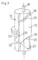
- the rotary piston machine shown in Figures 1 and 2 comprises a cylindrical housing 10 and a formed in the form of a tubular section annular piston 12, which in an annular cavity 14 of the cylindrical Housing 10 is rotatably guided and axially displaceable.
- the piston is via a radial bottom, which is indicated by dashed lines in Figure 1 and designated 16 or non-rotatably via radial spokes with a shaft 18, but axially on the shaft 18 slidably connected, which passes through the housing 10.
- Such an axial displacement enabling rotationally fixed connection can be effected for example via a spline, as shown in Figure 4.
- the annular space 14 has an annular end surface 20 which may have a rectilinear or curved cross-section and which extends in a wave-like manner in the circumferential direction with shaft amplitude directed parallel to the axis.
- the wavy line is approximately sinusoidal and, in the illustrated example, has two peaks or peaks 22 and two wave troughs or minima 24.
- the end face 20 of the annular space 14 facing end or end surface 26 of the annular piston 12 is also formed wave-shaped, as can be seen in Figure 1.
- This end face also has two maxima or wave peaks 28 and two wave troughs 30 (FIGS. 5 to 10).
- this wavy line is designed so that the measured in the circumferential direction half-width of a wave crest, i. the width of the wave crest in the axial center between a wave minimum and a wave maximum is less than the half width of a wave trough.
- the arrangement could also be reversed in that the end face 26 of the ring piston is sinusoidal and the end face 20 of the annulus 14 has narrower peaks and wider troughs.
- one of the inlet and outlet channels 32 can also be seen in the housing 10, which terminates at the inner boundary wall 15 of the annular space 14 and serves for supplying or discharging a working fluid to the annular space 14, as shown in FIGS. 5 to 16 will be explained in more detail.
- the piston 12 is tensioned by a coaxial with the shaft 18 arranged helical spring 34 against the end surface 20 of the annular space 14.
- a plate spring can be used, which can also serve to connect the piston rotation with the shaft. With the diaphragm spring, the axial length is shortened.
- the arrangement of the end surfaces 20 of the annular spaces 14 is selected so that the maxima and minima of the two end surfaces 20 are each on a common generatrix of the cylindrical annular spaces 14, as shown in FIGS. 5 to 16.
- the end faces 26 of the double piston 12 are shaped so that the maximum or crest 28 of one end face with a minimum or the trough 30 of the opposite end face is common to a generatrix of the cylindrical ring piston 12.
- 33 designates a guide groove formed in the radially outer wall of the annular space 14 into which a pin 35 fastened to the piston 12 engages.
- the guide groove follows in the circumferential direction of the waveform of the end surface 20 and thus controls the translational movement of the piston 12, without the end faces 20 and 26 touch. This solution is only optional.
- Figure 4a shows yet another way to reduce the sliding friction between the end surfaces 20 and 26 and thus the wear of these surfaces.
- a roller 37 is rotatably mounted so that it can roll on the end surface 20 of the annular space 14.
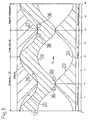
- FIGS. 5 to 10 relate to a rotary piston engine operated as a motor of the type described in FIGS. 3 and 4, the functional explanations of which also apply to the machine according to FIGS. 1 and 2.
- an inlet opening 36 and an outlet opening 38 are each provided on a circumference of 360 ° in such a way that relative to the pointing in the direction of arrow A circumferential direction of the piston 12, the outlet opening 38 in front of a wave crest 22 and the inlet opening 36 to the wave crest 22 is located.
- the shape of the inlet opening 36 and the outlet opening 38 is usually not circular in practice but is depending on the intended use of Rotary engine and also designed in the manner of the medium flowing through, in order to achieve optimum control of the medium flow.
- FIG. 5 shows the piston 12 at top dead center.
- four separate cavities are formed between the upper end surface 20 of the annular space 14 and the upper end surface 26 of the piston 12.
- the lying between 90 ° and 180 ° cavity contains a maximum compressed mixture at the time of ignition. From the lying between 180 ° and 270 ° cavity, the combustion gases were ejected.
- the outlet opening 38 has been closed.
- the inlet opening 36 is gradually opened, so that in the lying between 270 ° and 360 ° cavity mixture is sucked.
- the combustion space measured in the direction of rotation between 270 ° and 90 ° has reached its maximum extent.
- the outlet opening 38 is open.
- the piston 12 is located at its bottom dead center with respect to the lower end surface 20 and the exhaust of the combustion gases from the combustion chamber begins. In the second lying between 90 ° and 270 ° cavity mixture was sucked, which is now compressed with further rotating piston.
- Figure 6 shows the above indicated operations upon rotation of the piston 12 in the direction of the arrow A relative to the fixed housing 10.
- the upper inlet opening 36 is now open, so that mixture can be sucked.
- the outlet opening 38 is closed.
- the combustion chamber increases with the expanding combustion gases.
- In the lower part of the outlet channel is fully open, so that the fuel gases can be ejected while the inlet port is closed, thus allowing a compression in the specified range.
- Figure 8 shows the position inverse to Figure 5, i. the piston 12 is located with respect to the upper end surface 20 of the annular space 14 in its bottom dead center position and with respect to the lower end surface 20 of the annular space 14 in its upper dead center position.
- the state shown in Figure 5 then again follows the figure 10, in which the piston 12 has performed a revolution relative to the housing and thus the four clocks, namely suction, compression, combustion and expulsion of the engine.
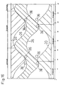
- FIGS. 11 to 16 show the same phases for a rotary piston machine designed as a pump. Since there are only two cycles per stroke, namely suction and discharge, two pairs of inlet port 36 (suction line) and outlet port 38 (pressure line) may be provided. Moreover, the operation of the two piston / annulus assemblies is again offset in the same manner by 180 ° to each other, as has already been described in the engine according to Figures 5 to 10.
Abstract
Description
Die Erfindung betrifft eine Drehkolbenmaschine gemäß dem Oberbegriff des Anspruchs 1.The invention relates to a rotary piston machine according to the preamble of claim 1.
Eine Drehkolbenmaschine der vorstehend genannten Art ist beispielsweise aus der WO-91/05940 bekannt. Bei der dort beschriebenen Drehkolbenmaschine, die als Pumpe, als Brennkraftmaschine oder Hydraulikmotor verwendbar ist, erfolgt die Zufuhr und die Abfuhr des Mediums zu den oder aus den Arbeitsräumen zwischen dem Rotor und den Statoren über Öffnungen, die in den Statorwellenflächen ausgebildet sind. Um die Einlaßöffnungen und die Auslaßöffnungen gegeneinander abzugrenzen, sind in der Rotorwellenfläche radial gerichtete Dichtungsleisten gelagert, die durch Federn gegen die jeweilige Statorwellenfläche gespannt werden. Es ist bei dieser Lösung jedoch schwierig, die Einlaß- und Auslaßöffnungen einerseits groß genug zu machen, um den Arbeitsraum mit dem Arbeitsmedium rasch und komplett zu füllen bzw. das Arbeitsmedium schnell wieder aus dem Arbeitsraum heraus zu treiben, und andererseits eine Überschneidung der Offnungs- und Schließzeiten von Einlaß- und Auslaßöffnung während eines Zyklus zu vermeiden.A rotary piston machine of the aforementioned type is known, for example, from WO-91/05940. In the rotary piston machine described therein, which can be used as a pump, as an internal combustion engine or hydraulic motor, the supply and the discharge of the medium to or from the working spaces between the rotor and the stators via openings formed in the Statorwellenflächen. In order to delimit the inlet openings and the outlet openings from one another, radially directed sealing strips are mounted in the rotor shaft surface and are tensioned by springs against the respective stator shaft surface. However, it is difficult in this solution to make the inlet and outlet openings on the one hand large enough to fill the working space with the working fluid quickly and completely or to drive the working fluid quickly out of the work space out, and on the other hand, an overlap of the opening and closing times of inlet and outlet ports during one cycle.
Der Erfindung liegt die Aufgabe zugrunde, eine Drehkolbenmaschine der eingangs genannten Art anzugeben, die einfach im Aufbau ist und bei der die Einlaß- und Auslaßöffnungen für das Arbeitsfluid auf einfache Weise gesteuert werden können.The invention has for its object to provide a rotary piston engine of the type mentioned, which is simple in construction and in which the inlet and outlet ports for the working fluid can be controlled in a simple manner.
Diese Aufgabe wird durch die im kennzeichnenden Teil des Anspruchs 1 angegebenen Merkmale gelöst.This object is achieved by the features stated in the characterizing part of claim 1.
Die erfindungsgemäße Drehkolbenmaschine kann als Pumpe oder, sofern die Wellenflächen des Ringraumes und des Ringkolbens mit mindestens zwei Wellenbergen und Wellentälern auf 360° des Umfanges ausgebildet sind, auch als Motor betrieben werden. In der Regel wird die Maschine so ausgebildet sein, daß das Gehäuse feststeht und der Kolben mit der Welle umläuft. Prinzipiell ist jedoch auch die entgegengesetzte Anordnung möglich, bei welcher sich das Gehäuse gegenüber dem nichtrotierenden Kolben dreht. Jedoch sind hier die Anschlüsse für die Zufuhr und die Abfuhr des Arbeitsfluides komplizierter. Der Kolben kann dabei auf der Welle axial verschiebbar gelagert sein oder starr mit der Welle verbunden sein, die ihrerseits axial verschiebbar in dem Gehäuse gelagert ist.The rotary piston engine according to the invention can be operated as a pump or, provided that the wave surfaces of the annular space and the annular piston with at least two wave crests and troughs on 360 ° of the circumference, are also operated as a motor. In general, the machine will be designed so that the housing is fixed and the piston rotates with the shaft. In principle, however, the opposite arrangement is possible in which the housing rotates relative to the non-rotating piston. However, here the connections for the supply and the discharge of the working fluid are more complicated. The piston can be axially displaceably mounted on the shaft or be rigidly connected to the shaft, which in turn is mounted axially displaceable in the housing.
Bei der erfindungsgemäßen Lösung wird der Arbeitsraum der Drehkolbenmaschine durch die variablen Hohlräume zwischen den aneinander gleitenden Endflächen des Ringraumes und des Ringkolben gebildet. Dabei vergrößert oder verkleinert sich der jeweilige Hohlraum sowohl durch die Drehung als auch die axiale Hubbewegung des Kolbens gegenüber dem Gehäuse. Die Einlaßöffnung und die Auslaßöffnung können in der radial äußeren oder radial inneren Mantel- oder Begrenzungsfläche des Ringraumes so angeordnet werden, daß sie zyklisch durch die Kolbenwand freigegeben und wieder geschlossen werden, um im Falle einer Pumpe beispielsweise ein Arbeitsfluid anzusaugen und wieder auszustoßen oder im Falle eines Motors ein Treibstoffgemisch anzusaugen, zu verdichten und anschließend die Verbrennungsgase wieder auszustoßen.In the solution according to the invention the working space of the rotary piston machine is formed by the variable cavities between the mutually sliding end surfaces of the annular space and the annular piston. In this case, the respective cavity increases or decreases both by the rotation and the axial stroke movement of the piston relative to the housing. The inlet opening and the outlet opening can be arranged in the radially outer or radially inner shell or boundary surface of the annular space so that they are cyclically released by the piston wall and closed again to suck in the case of a pump, for example, a working fluid and expel again or in the case an engine to draw in a fuel mixture, to compress and then expel the combustion gases again.
Da der Ringkolben bezüglich seiner Drehachse rotationssymmetrisch ausgebildet ist, erhält man einen völlig ruhigen Lauf des Kolbens. Das gleiche würde für ein rotierendes Gehäuse gelten. Es treten keine wesentlichen Dichtungsprobleme auf. Bewegliche Ventile sind für das Öffnen und Schließen der Einlaß- und Auslaßöffnungen nicht erforderlich.Since the annular piston is rotationally symmetrical with respect to its axis of rotation, one obtains a completely smooth running of the piston. The same would apply to a rotating housing. There are no significant sealing problems. Movable valves are not required for opening and closing the inlet and outlet ports.
Vorzugsweise sind die Einlaßöffnung und die Auslaßöffnung jeweils so angeordnet, daß eine der Öffnungen in Umfangsrichtung vor und die andere hinter einem Wellenberg der- Endfläche des Ringraumes liegt. Bei Ausbildung der Drehkolbenmaschine als Motor sind auf dem Umfang von 360° eine Einlaßöffnung und eine Auslaßöffnung vorgesehen. Bei Ausbildung der Drehkolbenmaschine als Pumpe sind vorzugsweise jeweils zwei Einlaßöffnungen und zwei Auslaßöffnungen pro Endfläche des Kolbens vorgesehen.Preferably, the inlet opening and the outlet opening are each arranged so that one of the openings in the circumferential direction before and the other is behind a wave crest of the end face of the annular space. When forming the rotary engine as an engine, an inlet opening and an outlet opening are provided on the circumference of 360 °. In training the rotary piston engine as Pump are preferably provided in each case two inlet openings and two outlet openings per end face of the piston.
Eine der Endflächen kann zumindest annähernd sinusförmig ausgebildet sein. Die andere wird vorzugsweise so gewählt, daß eine möglichst gleichförmige axiale Bewegung des Kolbens während einer Umdrehung erreicht wird und keine ruckartigen oder extremen Beschleunigungen des Kolbens in axialer Richtung auftreten.One of the end surfaces may be at least approximately sinusoidal. The other is preferably chosen so that as uniform as possible axial movement of the piston is achieved during a revolution and no jerky or extreme accelerations of the piston occur in the axial direction.
Bei einer ersten Ausführungsform der Erfindung wird der Kolben beispielsweise durch eine Feder in axialer Richtung so vorgespannt, daß seine Endfläche stets an der Endfläche des zugehörigen Ringraumes anliegt. Die Kraft, mit der die Flächen gegeneinander gedrückt werden, kann auch durch den Fluiddruck im Ringraum geregelt werden.In a first embodiment of the invention, the piston is biased, for example by a spring in the axial direction so that its end face always bears against the end face of the associated annular space. The force with which the surfaces are pressed against one another can also be regulated by the fluid pressure in the annular space.
Bei einer anderen Ausführungsform ist in einer Mantelfläche des Kolbens oder des Ringraumes eine Nut ausgebildet, in die ein mit dem jeweils anderen Teil (Ringraum, Kolben) verbundenes Führungselement eingreift, wobei der Verlauf der Nut in Umfangsrichtung dem der Wellenform der Endfläche des Ringraumes entspricht. Damit wird die Translationsbewegung des Kolbens und des Zylinders relativ zueinander durch die Nut gesteuert. Die Endflächen von Kolben und Ringraum müssen sich nicht berühren, sodaß der Verschleiß dieser Flächen durch das Aufeinandergleiten vermieden wird.In another embodiment, a groove is formed in a lateral surface of the piston or the annular space, in which engages a with the other part (annular space, piston) associated guide element, wherein the course of the groove in the circumferential direction corresponds to the waveform of the end surface of the annular space. Thus, the translational movement of the piston and the cylinder is controlled relative to each other through the groove. The end surfaces of the piston and annulus need not touch, so that the wear of these surfaces is avoided by the sliding on one another.
Eine andere Lösung, den Verschleiß der Endflächen durch Gleitreibung zu vermindern, besteht darin, daß in einer der einander zugewandten Endflächen von Ringraum und Kolben mindestens ein zur rollenden Anlage an der jeweils anderen Endfläche bestimmtes Führungselement drehbar gelagert ist.Another solution to reduce the wear of the end surfaces by sliding friction, is that in one of the mutually facing end surfaces of annulus and piston at least one specific for rolling contact with the other end face guide member is rotatably mounted.
Bei einer weiteren Ausführungsform der Erfindung sind zwei Ringraum-/Ringkolbenanordnungen der vorstehend genannten Art koaxial zueinander so angeordnet, daß die beiden auf derselben Welle angeordneten Kolben sich gemeinsam zwischen den Endflächen der beiden Ringräume bewegen.In a further embodiment of the invention, two annular space / annular piston arrangements of the aforementioned type are arranged coaxially with each other so that the two pistons arranged on the same shaft move together between the end surfaces of the two annular spaces.
Beispielsweise können die beiden Kolben zu einem einstückigen Doppelkolben vereinigt sein. Dabei sind die beiden Endflächen des Hohlraumes oder der beiden miteinander vereinigten Ringräume so zueinander angeordnet, daß die Maxima und Minima ihrer Wellenflächen jeweils auf denselben Erzeugenden der zylindrischen Mantelfläche des Hohlraumes liegen. Dadurch läßt sich sicherstellen, daß die beiden Endflächen des rotierenden Ringkolbens stets an beiden Endflächen des Hohlraums gleichzeitig gleiten, wenn der Kolben rotiert.For example, the two pistons can be combined to form a one-piece double piston. In this case, the two end surfaces of the cavity or the two annular spaces united with each other are arranged to each other that the maxima and minima of their wave surfaces each lie on the same generatrix of the cylindrical surface of the cavity. As a result, it can be ensured that the two end surfaces of the rotary ring piston always slide simultaneously on both end surfaces of the cavity when the piston rotates.
Die folgende Beschreibung erläutert in Verbindung mit den beigefügten Zeichnungen die Erfindung anhand von Ausführungsbeispielen. Es zeigen:
- Fig. 1
- eine schematische, perspektivische, teilweise aufgebrochene Darstellung einer ersten Ausführungsform einer erfindungsgemäßen Drehkolbenmaschine mit einer Kolben/Ringraumanordnung,
- Fig. 2
- einen die Achse enthaltenden Schnitt durch das Gehäuse der in Figur 1 dargestellten Anordnung,
- Fig. 3
- eine schematische perspektivische, teilweise aufgebrochene Darstellung einer Drehkolbenmaschine mit einem Doppelkolben,
- Fig. 4
- einen schematischen, die Achse enthaltenden Schnitt durch die Doppelkolbenanordnung gemäß Figur 3,
- Fig.4a
- die Einzelheit A aus Fig. 4 in vergrößertem Maßstab für eine abgewandelte Ausführungsform,
- Fig. 5 bis 10
- jeweils eine Abwicklungsdarstellung der aneinander gleitenden Endflächen des Gehäusehohlraumes und des Doppelkolbens einer als Motor arbeitenden Doppelkolbenmaschine gemäß den Figuren 3 und 4 und
- Fig. 11 bis 16
- den Figuren 5 bis 10 entsprechende Darstellungen einer Drehkolbenmaschine, die als Pumpe betrieben wird.
- Fig. 1
- 1 is a schematic, perspective, partially broken view of a first embodiment of a rotary piston engine according to the invention with a piston / annulus arrangement,
- Fig. 2
- a section containing the axis through the housing of the arrangement shown in Figure 1,
- Fig. 3
- a schematic perspective, partially broken view of a rotary piston machine with a double piston,
- Fig. 4
- 3 shows a schematic section containing the axis through the double piston arrangement according to FIG. 3,
- 4a
- the detail A of FIG. 4 on an enlarged scale for a modified embodiment,
- Fig. 5 to 10
- each a development view of the sliding end surfaces of the housing cavity and the double piston of a working as a motor double piston engine according to Figures 3 and 4 and
- Fig. 11 to 16
- Figures 5 to 10 corresponding representations of a rotary piston machine, which is operated as a pump.
Die in den Figuren 1 und 2 dargestellte Drehkolbenmaschine umfaßt ein zylindrisches Gehäuse 10 und einen in Form eines Rohrabschnittes ausgebildeten Ringkolben 12, der in einem ringförmigen Hohlraum 14 des zylindrischen Gehäuses 10 drehbar und axial verschiebbar geführt ist. Der Kolben ist über einen radialen Boden, der in Figur 1 gestrichelt angedeutet und mit 16 bezeichnet ist oder über radiale Speichen mit einer Welle 18 drehfest, aber axial auf der Welle 18 verschiebbar verbunden, welche das Gehäuse 10 durchsetzt. Eine solche eine axiale Verschiebung ermöglichende drehfeste Verbindung kann beispielsweise über eine Keilverzahnung erfolgen, wie dies in Figur 4 dargestellt ist.The rotary piston machine shown in Figures 1 and 2 comprises a
Der Ringraum 14 hat eine ringförmige Endfläche 20, die einen geradlinigen oder gekrümmten Querschnitt haben kann und die in Umfangsrichtung wellenförmig verläuft mit achsparallel gerichteter Wellenamplitude. Wie man in den Figuren 5 bis 10 erkennt, ist die Wellenlinie annähernd sinusförmig und hat in dem dargestellten Beispiel zwei Wellenberge oder Maxima 22 sowie zwei Wellentäler oder Minima 24.The
Die der Endfläche 20 des Ringraumes 14 zugewandte Stirn- oder Endfläche 26 des Ringkolbens 12 ist ebenfalls wellenlinienförmig ausgebildet, wie dies in der Figur 1 zu erkennen ist. Auch diese Endfläche hat zwei Maxima oder Wellenberge 28 und zwei Wellentäler 30 (Figuren 5 bis 10). Diese Wellenlinie ist jedoch so ausgebildet, daß die in Umfangsrichtung gemessene Halbwertsbreite eines Wellenberges, d.h. die Breite des Wellenberges in der axialen Mitte zwischen einem Wellenminimum und einem Wellenmaximum geringer als die Halbwertsbreite eines Wellentales ist. Die Anordnung könnte auch insofern umgekehrt gewählt sein, als die Endfläche 26 des Ringkolbens sinusförmig gewählt ist und die Endfläche 20 des Ringraumes 14 schmalere Wellenberge und breitere Wellentäler hat.The end face 20 of the
In Figur 2 ist ferner in dem Gehäuse 10 einer der Einlaß- und Auslaßkanäle 32 zu erkennen, der an der inneren Begrenzungswand 15 des Ringraumes 14 endet und zum Zuführen oder Abführen eines Arbeitsfluides zu dem Ringraum 14 dient, wie dies anhand der Figuren 5 bis 16 noch näher erläutert wird.In FIG. 2, one of the inlet and
Der Kolben 12 wird durch eine koaxial zur Welle 18 angeordnete Schraubenfeder 34 gegen die Endfläche 20 des Ringraumes 14 gespannt. Anstelle der Schraubenfeder kann auch eine Tellerfeder verwendet werden, die gleichzeitig dazu dienen kann, den Kolben drehfest mit der Welle zu verbinden. Mit der Tellerfeder wird die axiale Baulänge verkürzt.The
Bei der in den Figuren 3 und 4 dargestellten Ausführungsform der erfindungsgemäßen Drehkolbenmaschine sind zwei Kolben/Gehäuseanordnungen der in Figur 1 dargestellten Art koaxial zueinander angeordnet, wobei die Feder 34 entfällt. Die beiden Kolben sind zu einem einzigen Doppelkolben vereinigt, wobei in den Figuren gleiche Teile mit gleichen Bezugszeichen wie in den Figuren 1 und 2 bezeichnet sind.In the embodiment of the rotary piston engine according to the invention shown in Figures 3 and 4, two piston / housing assemblies of the type shown in Figure 1 are arranged coaxially with each other, wherein the
Die Anordnung der Endflächen 20 der Ringräume 14 ist so gewählt, daß die Maxima und Minima der beiden Endflächen 20 jeweils auf einer gemeinsamen Erzeugenden der zylindrischen Ringräume 14 liegen, wie dies auch die Figuren 5 bis 16 zeigen.The arrangement of the end surfaces 20 of the
Die Endflächen 26 des Doppelkolbens 12 dagegen sind so geformt, daß das Maximum oder der Wellenberg 28 der einen Endfläche mit einem Minimum oder dem Wellental 30 der entgegengesetzten Endfläche gemeinsam auf einer Erzeugenden des zylindrischen Ringkolbens 12 liegt.On the other hand, the end faces 26 of the
In Figur 3 ist mit 33 eine in der radial äußeren Wand des Ringraumes 14 ausgebildete Führungsnut bezeichnet, in die ein an dem Kolben 12 befestigter Zapfen 35 eingreift. Die Führungsnut folgt in Umfangsrichtung der Wellenform der Endfläche 20 und steuert so die Translationsbewegung des Kolbens 12, ohne daß sich die Endflächen 20 und 26 berühren. Diese Lösung ist aber nur optional.In FIG. 3, 33 designates a guide groove formed in the radially outer wall of the
Figur 4a zeigt noch eine weitere Möglichkeit, die Gleitreibung zwischen den Endflächen 20 und 26 und damit den Verschleiß dieser Flächen zu vermindern. In einer Aussparung in der Endfläche 26 des Kolbens 12 ist eine Rolle 37 drehbar gelagert, sodaß sie auf der Endfläche 20 des Ringraumes 14 rollen kann.Figure 4a shows yet another way to reduce the sliding friction between the end surfaces 20 and 26 and thus the wear of these surfaces. In a recess in the
Die Figuren 5 bis 10 betreffen eine als Motor betriebene Drehkolbenmaschine der in den Figuren 3 und 4 beschriebenen Art, wobei die funktionalen Erläuterungen hierzu aber ebenso für die Maschine gemäß den Figuren 1 und 2 gelten. Pro Zylinder sind auf einem Umfang von 360° je eine Einlaßöffnung 36 und eine Auslaßöffnung 38 vorgesehen und zwar so, daß bezogen auf die in Richtung des Pfeiles A weisende Umlaufrichtung des Kolbens 12 die Auslaßöffnung 38 vor einem Wellenberg 22 und die Einlaßöffnung 36 nach dem Wellenberg 22 liegt. Die Form der Einlaßöffnung 36 und der Auslaßöffnung 38 ist in der Praxis meist nicht kreisförmig sondern wird je nach Verwendungszweck der Drehkolbenmaschine und auch nach Art des durchströmenden Mediums gestaltet, um eine optimale Steuerung des Mediumdurchflusses zu erreichen.FIGS. 5 to 10 relate to a rotary piston engine operated as a motor of the type described in FIGS. 3 and 4, the functional explanations of which also apply to the machine according to FIGS. 1 and 2. Per cylinder, an
Figur 5 zeigt den Kolben 12 im oberen Totpunkt. Dabei sind zwischen der oberen Endfläche 20 des Ringraumes 14 und der oberen Endfläche 26 des Kolbens 12 vier voneinander getrennte Hohlräume gebildet. Der zwischen 90° und 180° liegende Hohlraum enthält ein maximal verdichtetes Gemisch zum Zündzeitpunkt. Aus dem zwischen 180° und 270° liegenden Hohlraum wurden die Verbrennungsgase ausgestoßen. Die Auslaßöffnung 38 wurde geschlossen. Bei einer Drehung des Kolbens 12 in Richtung des Pfeiles A wird die Einlaßöffnung 36 allmählich geöffnet, so daß in den zwischen 270° und 360° liegenden Hohlraum Gemisch angesaugt wird. In der unteren Hälfte dagegen hat der in Umlaufrichtung zwischen 270° und 90° gemessene Verbrennungsraum seine maximale Ausdehnung erreicht. Die Auslaßöffnung 38 ist offen. Der Kolben 12 befindet sich bezüglich der unteren Endfläche 20 in seinem unteren Totpunkt und der Ausschub der Verbrennungsgase aus dem Brennraum beginnt. In dem zweiten zwischen 90° und 270° liegenden Hohlraum wurde Gemisch angesaugt, das nun bei sich weiter drehendem Kolben verdichtet wird.FIG. 5 shows the
Figur 6 zeigt die vorstehend angedeuteten Vorgänge bei einer Drehung des Kolbens 12 in Richtung des Pfeiles A relativ zu dem feststehenden Gehäuse 10. Die obere Einlaßöffnung 36 ist nun offen, so daß Gemisch angesaugt werden kann. Die Auslaßöffnung 38 ist geschlossen. Der Brennraum vergrößert sich mit den sich ausdehnenden Verbrennungsgasen. Im unteren Teil ist der Auslaßkanal vollständig geöffnet, so daß die Brenngase ausgeschoben werden können, während die Einlaßöffnung geschlossen ist und somit eine Verdichtung in dem angegebenen Bereich ermöglicht. Die Figur 8 zeigt die zu der Figur 5 inverse Stellung, d.h. der Kolben 12 befindet sich bezüglich der oberen Endfläche 20 des Ringraumes 14 in seiner unteren Totpunktstellung und bezüglich der unteren Endfläche 20 des Ringraumes 14 in seiner oberen Totpunktstellung. An die Figur 10 schließt sich dann wieder der in Figur 5 dargestellte Zustand an, in dem der Kolben 12 eine Umdrehung relativ zum Gehäuse und damit die vier Takte, nämlich Ansaugen, Verdichten, Verbrennen und Ausstoßen des Motors ausgeführt hat.Figure 6 shows the above indicated operations upon rotation of the
Man erkennt, daß die Steuerung der Einlaß- und Auslaßöffnungen vollständig ohne Ventile allein durch den Kolben selbst möglich ist und daß außer dem rotierenden und axial oszillierenden Kolben sowie der Welle keine weiteren beweglichen Teile erforderlich sind. Insbesondere werden keine beweglichen Dichtungselemente benötigt. Da der Kolben völlig symmetrisch aufgebaut ist, tritt auch keine Unwucht auf, welche die Lager oder die Welle beanspruchen würde.It can be seen that the control of the inlet and outlet ports is completely possible without valves alone by the piston itself and that except the rotating and axially oscillating piston and the shaft no further moving parts are required. In particular, no movable sealing elements are needed. Since the piston is constructed completely symmetrical, no imbalance occurs, which would claim the bearings or the shaft.
Die Figuren 11 bis 16 zeigen die gleichen Phasen für eine als Pumpe ausgebildete Drehkolbenmaschine. Da es hier nur zwei Takte pro Arbeitshub gibt, nämlich Ansaugen und Ausstoßen, können zwei Paare von Einlaßöffnung 36 (Saugleitung) und Auslaßöffnung 38 (Druckleitung) vorgesehen sein. Im übrigen ist die Arbeitsweise der beiden Kolben/Ringraumanordnungen wieder in der gleichen Weise um 180° gegeneinander versetzt, wie dies bereits bei dem Motor gemäß den Figuren 5 bis 10 beschrieben wurde.FIGS. 11 to 16 show the same phases for a rotary piston machine designed as a pump. Since there are only two cycles per stroke, namely suction and discharge, two pairs of inlet port 36 (suction line) and outlet port 38 (pressure line) may be provided. Moreover, the operation of the two piston / annulus assemblies is again offset in the same manner by 180 ° to each other, as has already been described in the engine according to Figures 5 to 10.
Claims (14)
- Rotary piston machine with a housing (10) and a piston (12) which is arranged in a rotatable way in a hollow space of the housing (10) and is connected in a rotationally secure way to a shaft (18) going through the housing wherein at least one inlet and one outlet channel (32) are formed in the housing (10) for the supply or removal of a working fluid to or from the hollow space which has a section in the form of a cylindrical annular space (14) which is coaxial to the shaft (18) wherein the piston (12) is formed as an annular piston in the form of a cylindrical pipe section which engages in the annular space (14) of the housing (10) and is guided in this in an axially displaceable way and wherein the end areas facing each other (20, 26) of the annular space (14) and the annular piston (12) are formed as constantly undulating surfaces with axis-parallel oriented amplitude, characterised in that the inlet and outlet openings (36, 38) lie within an axial region of the annular space lateral area which is determined by the maximum axial distance of the valleys (24, 20) of the end areas (20, 26) facing each other.
- Rotary piston machine according to claim 1, characterised in that at least two lobes (22, 28) and two valleys (24, 30) are provided on 360° of the circumference wherein the half-width measured in the circumferential direction of the lobes (28) of at least one of the end areas is smaller than that of the valleys (30) of the same end area.
- Rotary piston machine according to claim 1 or 2, characterised in that the piston (12) is mounted in an axially displaceable way on the shaft (18).
- Rotary piston machine according to claim 1 or 2, characterised in that the piston (12) is rigidly connected to the shaft (18) and the latter is mounted in an axially displaceable way in the housing (10).
- Rotary piston machine according to one of the claims 1 to 4, characterised in that the piston (12) is pretensioned in the direction of the end area (20) of the annular space (14).
- Rotary piston machine according to one of the claims 1 to 4, characterised in that in a lateral area of the piston (12) or of the annular space (14) a groove (33) is formed, in which a guide element (35) connected to the other part (annular space (14), piston (12)) engages wherein the form of the groove in the circumferential direction corresponds to that of the undulating form of the end area (20) of the annular space (14).
- Rotary piston machine according to one of the claims 1 to 4, characterised in that in one of the facing end areas (20, 26) of the annular space (14) and piston (12) a guide element (37) intended for rolling arrangement on the other end area is mounted in a rotatable way.
- Rotary piston machine according to one of the claims 1 to 7, characterised in that the inlet opening (36) and the outlet opening (38) are arranged in the circumferential direction in front of or behind a lobe (22) of the end area (20) of the annular space (14).
- Rotary piston machine according to one of the claims 2 to 8, characterised in that when used as a pump at least two inlet openings (36) and two outlet openings (38) are provided for each end area of the piston (12).
- Rotary piston machine according to one of the claims 1 to 9, characterised in that the inlet opening and / or the outlet opening is / are provided on the radially inner boundary wall (15) of the annular space (14).
- Rotary piston machine according to one of the claims 1 to 10, characterised in that one of the end areas (20, 26) coming into contact with each other is formed in a sinusoidal way.
- Rotary piston machine according to one of the claims 1 to 11, characterised in that two annular space / annular piston arrangements (14, 12) are arranged coaxially to each other according to one of the claims 1 to 5 in such a way that the two pistons (12) arranged on the same shaft (18) move in common between the end areas (20) of the two annular spaces (14).
- Rotary piston machine according to claim 12, characterised in that the two pistons form an integral double piston (12).
- Rotary piston machine according to claim 12 or 13, characterised in that the maxima and minima of the two identically formed end areas (20) of the annular space (14) lie on the same generatrix of the cylindrical lateral area of the annular space (14) and that the maximum (28) of one end area (26) of the two pistons (12) lies with a minimum (30) of the other end area (26) in common on a generatrix of the piston lateral area.
Applications Claiming Priority (3)
| Application Number | Priority Date | Filing Date | Title |
|---|---|---|---|
| DE19953168A DE19953168A1 (en) | 1999-11-04 | 1999-11-04 | Rotary lobe machine |
| DE19953168 | 1999-11-04 | ||
| PCT/EP2000/010831 WO2001033047A1 (en) | 1999-11-04 | 2000-11-03 | Rotary piston machine |
Publications (2)
| Publication Number | Publication Date |
|---|---|
| EP1226338A1 EP1226338A1 (en) | 2002-07-31 |
| EP1226338B1 true EP1226338B1 (en) | 2006-02-08 |
Family
ID=7927946
Family Applications (1)
| Application Number | Title | Priority Date | Filing Date |
|---|---|---|---|
| EP00974505A Expired - Lifetime EP1226338B1 (en) | 1999-11-04 | 2000-11-03 | Rotary piston machine |
Country Status (7)
| Country | Link |
|---|---|
| US (1) | US6729862B1 (en) |
| EP (1) | EP1226338B1 (en) |
| JP (1) | JP2003514163A (en) |
| AT (1) | ATE317492T1 (en) |
| AU (1) | AU1278401A (en) |
| DE (2) | DE19953168A1 (en) |
| WO (1) | WO2001033047A1 (en) |
Families Citing this family (4)
| Publication number | Priority date | Publication date | Assignee | Title |
|---|---|---|---|---|
| DE10156835C1 (en) * | 2001-11-20 | 2003-04-30 | Peter Schnabl | Rotary piston pump for conveying media comprises an annular piston having control pockets opening toward its axial end surface for controlling inlet and outlet openings |
| DE102004019373B4 (en) * | 2004-04-21 | 2013-04-18 | Peter Schnabl | Rotary engine |
| WO2010068774A2 (en) * | 2008-12-11 | 2010-06-17 | Magnamotor, Llc | Magnetic piston apparatus and method |
| GR20180100001A (en) * | 2018-01-03 | 2019-09-06 | Γεωργιτζικη, Ελπιδα Γεωργιου | Mechanism converting the oscillatory motion into rotary and vice versa - applications of said mechanism |
Family Cites Families (11)
| Publication number | Priority date | Publication date | Assignee | Title |
|---|---|---|---|---|
| US1430602A (en) * | 1921-04-29 | 1922-10-03 | Sykora Rudolf | Rotary pump |
| US2517279A (en) * | 1944-04-06 | 1950-08-01 | Benzler Bengt Lennart | Control device for rotary reciprocating engines |
| US3667876A (en) * | 1970-12-21 | 1972-06-06 | Michael David Boyd | Rotary fluid flow machines |
| DE2733574A1 (en) * | 1977-07-26 | 1979-02-08 | Hans Frank | Rotary piston IC engine - has two coaxial opposed rotating pistons in one cylinder and with scroll faces shuttling free piston between them |
| BR7805823A (en) * | 1978-09-06 | 1981-10-27 | C Parente | ROTATING PUMP OF OSCILLATING PUMP IN AXIAL DIRECTION WITH FLOW CONTROL AND REVERSION |
| GB2075122A (en) * | 1980-04-14 | 1981-11-11 | Jayasooriya L | Rotary positive-displacement fluid-machines |
| GB8922993D0 (en) * | 1989-10-12 | 1989-11-29 | Richards Kevin | Pump or motor |
| DK0597855T3 (en) * | 1991-08-06 | 1997-06-16 | William A Goodman | Circular rotary engine |
| JP4056600B2 (en) * | 1996-11-19 | 2008-03-05 | 幸男 梶野 | Disc type rotation engine |
| CA2215219C (en) * | 1996-11-19 | 2000-07-04 | Yukio Kajino | Disc-type rotary engine |
| IT1288494B1 (en) | 1996-11-20 | 1998-09-22 | Sasib Spa | METHOD AND DEVICE FOR THE CONTROL WITHOUT DIRECT CONTACT OF THE HEADS OF THE CIGARETTES, OR SIMILAR. |
-
1999
- 1999-11-04 DE DE19953168A patent/DE19953168A1/en not_active Withdrawn
-
2000
- 2000-11-03 AT AT00974505T patent/ATE317492T1/en not_active IP Right Cessation
- 2000-11-03 AU AU12784/01A patent/AU1278401A/en not_active Abandoned
- 2000-11-03 WO PCT/EP2000/010831 patent/WO2001033047A1/en active IP Right Grant
- 2000-11-03 DE DE50012205T patent/DE50012205D1/en not_active Expired - Lifetime
- 2000-11-03 US US10/129,343 patent/US6729862B1/en not_active Expired - Fee Related
- 2000-11-03 JP JP2001535711A patent/JP2003514163A/en active Pending
- 2000-11-03 EP EP00974505A patent/EP1226338B1/en not_active Expired - Lifetime
Also Published As
| Publication number | Publication date |
|---|---|
| WO2001033047A1 (en) | 2001-05-10 |
| JP2003514163A (en) | 2003-04-15 |
| AU1278401A (en) | 2001-05-14 |
| US6729862B1 (en) | 2004-05-04 |
| EP1226338A1 (en) | 2002-07-31 |
| ATE317492T1 (en) | 2006-02-15 |
| DE50012205D1 (en) | 2006-04-20 |
| DE19953168A1 (en) | 2001-05-10 |
Similar Documents
| Publication | Publication Date | Title |
|---|---|---|
| DE3444859C2 (en) | ||
| DE3690061C2 (en) | Rotary piston machine | |
| DE1553238B2 (en) | Rotary piston machine | |
| WO1998013583A1 (en) | Oscillating piston engine | |
| EP1226338B1 (en) | Rotary piston machine | |
| DE3331636C2 (en) | Unit consisting of a reciprocating piston engine and a gearbox | |
| DE1926050A1 (en) | Radial piston machine, especially radial piston motor | |
| DE2209996A1 (en) | Adjustable liquid device of the displacer design | |
| DE2848220A1 (en) | ROTARY PISTON ENGINE | |
| DE2921311C2 (en) | ||
| DE69931181T2 (en) | ROTATION PUMP | |
| EP0316346B1 (en) | Rotating piston machine | |
| DE4224075A1 (en) | Hydraulic drive and braking system | |
| DE2153946C2 (en) | Guide transmission for rotary piston engine - has crankshaft with eccentric outside rotor, with rotary guide disc adjacent to rotor front face | |
| EP0561855B1 (en) | Rotating piston machine | |
| DE19520402C2 (en) | Hydraulic rotary piston engine | |
| CH430627A (en) | Radial piston machine | |
| DE1266648B (en) | Rotary piston machine | |
| DE2333486A1 (en) | PISTON PUMP OR MOTOR WITH A REVOLVING CYLINDER | |
| DE3508408A1 (en) | Rotary engine | |
| DE1528983C3 (en) | Control rotary valve device for a rotary piston machine | |
| AT219623B (en) | Engine or work machine with at least one rotary piston rotating in an annular cylinder | |
| DE2134565C3 (en) | Rotary piston-like rotary piston machine | |
| EP1984600A1 (en) | Adjustable segment expeller | |
| DE1927954A1 (en) | Rotary pump or motor for liquid or gaseous medium |
Legal Events
| Date | Code | Title | Description |
|---|---|---|---|
| PUAI | Public reference made under article 153(3) epc to a published international application that has entered the european phase |
Free format text: ORIGINAL CODE: 0009012 |
|
| 17P | Request for examination filed |
Effective date: 20020430 |
|
| AK | Designated contracting states |
Kind code of ref document: A1 Designated state(s): AT BE CH CY DE DK ES FI FR GB GR IE IT LI LU MC NL PT SE TR |
|
| AX | Request for extension of the european patent |
Free format text: AL;LT;LV;MK;RO;SI |
|
| GRAP | Despatch of communication of intention to grant a patent |
Free format text: ORIGINAL CODE: EPIDOSNIGR1 |
|
| GRAS | Grant fee paid |
Free format text: ORIGINAL CODE: EPIDOSNIGR3 |
|
| GRAA | (expected) grant |
Free format text: ORIGINAL CODE: 0009210 |
|
| AK | Designated contracting states |
Kind code of ref document: B1 Designated state(s): AT BE CH CY DE DK ES FI FR GB GR IE IT LI LU MC NL PT SE TR |
|
| PG25 | Lapsed in a contracting state [announced via postgrant information from national office to epo] |
Ref country code: IT Free format text: LAPSE BECAUSE OF FAILURE TO SUBMIT A TRANSLATION OF THE DESCRIPTION OR TO PAY THE FEE WITHIN THE PRESCRIBED TIME-LIMIT;WARNING: LAPSES OF ITALIAN PATENTS WITH EFFECTIVE DATE BEFORE 2007 MAY HAVE OCCURRED AT ANY TIME BEFORE 2007. THE CORRECT EFFECTIVE DATE MAY BE DIFFERENT FROM THE ONE RECORDED. Effective date: 20060208 Ref country code: NL Free format text: LAPSE BECAUSE OF FAILURE TO SUBMIT A TRANSLATION OF THE DESCRIPTION OR TO PAY THE FEE WITHIN THE PRESCRIBED TIME-LIMIT Effective date: 20060208 Ref country code: FI Free format text: LAPSE BECAUSE OF FAILURE TO SUBMIT A TRANSLATION OF THE DESCRIPTION OR TO PAY THE FEE WITHIN THE PRESCRIBED TIME-LIMIT Effective date: 20060208 Ref country code: GB Free format text: LAPSE BECAUSE OF FAILURE TO SUBMIT A TRANSLATION OF THE DESCRIPTION OR TO PAY THE FEE WITHIN THE PRESCRIBED TIME-LIMIT Effective date: 20060208 Ref country code: IE Free format text: LAPSE BECAUSE OF FAILURE TO SUBMIT A TRANSLATION OF THE DESCRIPTION OR TO PAY THE FEE WITHIN THE PRESCRIBED TIME-LIMIT Effective date: 20060208 |
|
| REG | Reference to a national code |
Ref country code: GB Ref legal event code: FG4D Free format text: NOT ENGLISH |
|
| REG | Reference to a national code |
Ref country code: CH Ref legal event code: EP |
|
| REG | Reference to a national code |
Ref country code: IE Ref legal event code: FG4D Free format text: LANGUAGE OF EP DOCUMENT: GERMAN |
|
| REF | Corresponds to: |
Ref document number: 50012205 Country of ref document: DE Date of ref document: 20060420 Kind code of ref document: P |
|
| PG25 | Lapsed in a contracting state [announced via postgrant information from national office to epo] |
Ref country code: SE Free format text: LAPSE BECAUSE OF FAILURE TO SUBMIT A TRANSLATION OF THE DESCRIPTION OR TO PAY THE FEE WITHIN THE PRESCRIBED TIME-LIMIT Effective date: 20060508 Ref country code: DK Free format text: LAPSE BECAUSE OF FAILURE TO SUBMIT A TRANSLATION OF THE DESCRIPTION OR TO PAY THE FEE WITHIN THE PRESCRIBED TIME-LIMIT Effective date: 20060508 |
|
| PG25 | Lapsed in a contracting state [announced via postgrant information from national office to epo] |
Ref country code: ES Free format text: LAPSE BECAUSE OF FAILURE TO SUBMIT A TRANSLATION OF THE DESCRIPTION OR TO PAY THE FEE WITHIN THE PRESCRIBED TIME-LIMIT Effective date: 20060519 |
|
| NLV1 | Nl: lapsed or annulled due to failure to fulfill the requirements of art. 29p and 29m of the patents act | ||
| PG25 | Lapsed in a contracting state [announced via postgrant information from national office to epo] |
Ref country code: PT Free format text: LAPSE BECAUSE OF FAILURE TO SUBMIT A TRANSLATION OF THE DESCRIPTION OR TO PAY THE FEE WITHIN THE PRESCRIBED TIME-LIMIT Effective date: 20060710 |
|
| GBV | Gb: ep patent (uk) treated as always having been void in accordance with gb section 77(7)/1977 [no translation filed] |
Effective date: 20060208 |
|
| REG | Reference to a national code |
Ref country code: IE Ref legal event code: FD4D |
|
| PG25 | Lapsed in a contracting state [announced via postgrant information from national office to epo] |
Ref country code: CH Free format text: LAPSE BECAUSE OF NON-PAYMENT OF DUE FEES Effective date: 20061130 Ref country code: BE Free format text: LAPSE BECAUSE OF NON-PAYMENT OF DUE FEES Effective date: 20061130 Ref country code: LI Free format text: LAPSE BECAUSE OF NON-PAYMENT OF DUE FEES Effective date: 20061130 Ref country code: MC Free format text: LAPSE BECAUSE OF NON-PAYMENT OF DUE FEES Effective date: 20061130 |
|
| PLBE | No opposition filed within time limit |
Free format text: ORIGINAL CODE: 0009261 |
|
| STAA | Information on the status of an ep patent application or granted ep patent |
Free format text: STATUS: NO OPPOSITION FILED WITHIN TIME LIMIT |
|
| 26N | No opposition filed |
Effective date: 20061109 |
|
| EN | Fr: translation not filed | ||
| REG | Reference to a national code |
Ref country code: CH Ref legal event code: PL |
|
| BERE | Be: lapsed |
Owner name: SCHNABL, PETER Effective date: 20061130 |
|
| PG25 | Lapsed in a contracting state [announced via postgrant information from national office to epo] |
Ref country code: AT Free format text: LAPSE BECAUSE OF NON-PAYMENT OF DUE FEES Effective date: 20061103 |
|
| PG25 | Lapsed in a contracting state [announced via postgrant information from national office to epo] |
Ref country code: GR Free format text: LAPSE BECAUSE OF FAILURE TO SUBMIT A TRANSLATION OF THE DESCRIPTION OR TO PAY THE FEE WITHIN THE PRESCRIBED TIME-LIMIT Effective date: 20060509 Ref country code: FR Free format text: LAPSE BECAUSE OF FAILURE TO SUBMIT A TRANSLATION OF THE DESCRIPTION OR TO PAY THE FEE WITHIN THE PRESCRIBED TIME-LIMIT Effective date: 20070330 |
|
| PG25 | Lapsed in a contracting state [announced via postgrant information from national office to epo] |
Ref country code: TR Free format text: LAPSE BECAUSE OF FAILURE TO SUBMIT A TRANSLATION OF THE DESCRIPTION OR TO PAY THE FEE WITHIN THE PRESCRIBED TIME-LIMIT Effective date: 20060208 Ref country code: LU Free format text: LAPSE BECAUSE OF NON-PAYMENT OF DUE FEES Effective date: 20061103 |
|
| PG25 | Lapsed in a contracting state [announced via postgrant information from national office to epo] |
Ref country code: FR Free format text: LAPSE BECAUSE OF FAILURE TO SUBMIT A TRANSLATION OF THE DESCRIPTION OR TO PAY THE FEE WITHIN THE PRESCRIBED TIME-LIMIT Effective date: 20060208 Ref country code: CY Free format text: LAPSE BECAUSE OF FAILURE TO SUBMIT A TRANSLATION OF THE DESCRIPTION OR TO PAY THE FEE WITHIN THE PRESCRIBED TIME-LIMIT Effective date: 20060208 |
|
| PGFP | Annual fee paid to national office [announced via postgrant information from national office to epo] |
Ref country code: DE Payment date: 20101230 Year of fee payment: 11 |
|
| REG | Reference to a national code |
Ref country code: DE Ref legal event code: R119 Ref document number: 50012205 Country of ref document: DE Effective date: 20120601 |
|
| PG25 | Lapsed in a contracting state [announced via postgrant information from national office to epo] |
Ref country code: DE Free format text: LAPSE BECAUSE OF NON-PAYMENT OF DUE FEES Effective date: 20120601 |