EP1555952B1 - Dispositif de stockage et d'application de substances visqueuses - Google Patents
Dispositif de stockage et d'application de substances visqueuses Download PDFInfo
- Publication number
- EP1555952B1 EP1555952B1 EP03753565A EP03753565A EP1555952B1 EP 1555952 B1 EP1555952 B1 EP 1555952B1 EP 03753565 A EP03753565 A EP 03753565A EP 03753565 A EP03753565 A EP 03753565A EP 1555952 B1 EP1555952 B1 EP 1555952B1
- Authority
- EP
- European Patent Office
- Prior art keywords
- chambers
- chamber
- duct
- applicator
- outputting
- Prior art date
- Legal status (The legal status is an assumption and is not a legal conclusion. Google has not performed a legal analysis and makes no representation as to the accuracy of the status listed.)
- Expired - Lifetime
Links
- 239000011345 viscous material Substances 0.000 title claims description 19
- 239000000126 substance Substances 0.000 claims description 72
- 238000002156 mixing Methods 0.000 claims description 63
- 239000010408 film Substances 0.000 claims description 44
- 239000013039 cover film Substances 0.000 claims description 21
- 239000000203 mixture Substances 0.000 claims description 14
- 238000005452 bending Methods 0.000 claims description 12
- 239000007788 liquid Substances 0.000 description 31
- 239000011888 foil Substances 0.000 description 23
- 238000003860 storage Methods 0.000 description 22
- 239000000463 material Substances 0.000 description 18
- 238000004806 packaging method and process Methods 0.000 description 9
- 238000004519 manufacturing process Methods 0.000 description 8
- VYPSYNLAJGMNEJ-UHFFFAOYSA-N Silicium dioxide Chemical compound O=[Si]=O VYPSYNLAJGMNEJ-UHFFFAOYSA-N 0.000 description 6
- 230000009969 flowable effect Effects 0.000 description 5
- 230000002093 peripheral effect Effects 0.000 description 5
- 241000183024 Populus tremula Species 0.000 description 4
- 239000000853 adhesive Substances 0.000 description 4
- 230000001070 adhesive effect Effects 0.000 description 4
- 210000005224 forefinger Anatomy 0.000 description 4
- 210000004247 hand Anatomy 0.000 description 4
- 239000004033 plastic Substances 0.000 description 4
- 230000001681 protective effect Effects 0.000 description 4
- 238000007789 sealing Methods 0.000 description 4
- 210000003813 thumb Anatomy 0.000 description 4
- MHAJPDPJQMAIIY-UHFFFAOYSA-N Hydrogen peroxide Chemical compound OO MHAJPDPJQMAIIY-UHFFFAOYSA-N 0.000 description 3
- 230000001154 acute effect Effects 0.000 description 3
- 238000004026 adhesive bonding Methods 0.000 description 3
- 230000000295 complement effect Effects 0.000 description 3
- 230000006835 compression Effects 0.000 description 3
- 238000007906 compression Methods 0.000 description 3
- 238000013461 design Methods 0.000 description 3
- 238000007599 discharging Methods 0.000 description 3
- 239000000377 silicon dioxide Substances 0.000 description 3
- 230000003313 weakening effect Effects 0.000 description 3
- 239000011149 active material Substances 0.000 description 2
- 239000003708 ampul Substances 0.000 description 2
- 230000015572 biosynthetic process Effects 0.000 description 2
- 238000004061 bleaching Methods 0.000 description 2
- 238000011109 contamination Methods 0.000 description 2
- 230000000694 effects Effects 0.000 description 2
- 239000006260 foam Substances 0.000 description 2
- 238000000034 method Methods 0.000 description 2
- 238000003825 pressing Methods 0.000 description 2
- 238000005086 pumping Methods 0.000 description 2
- 238000000926 separation method Methods 0.000 description 2
- 238000003466 welding Methods 0.000 description 2
- 241001155433 Centrarchus macropterus Species 0.000 description 1
- 230000004913 activation Effects 0.000 description 1
- 239000013543 active substance Substances 0.000 description 1
- XAGFODPZIPBFFR-UHFFFAOYSA-N aluminium Chemical compound [Al] XAGFODPZIPBFFR-UHFFFAOYSA-N 0.000 description 1
- 229910052782 aluminium Inorganic materials 0.000 description 1
- 238000004458 analytical method Methods 0.000 description 1
- 238000013459 approach Methods 0.000 description 1
- 230000000903 blocking effect Effects 0.000 description 1
- 239000012928 buffer substance Substances 0.000 description 1
- 239000000969 carrier Substances 0.000 description 1
- 238000004891 communication Methods 0.000 description 1
- 239000002131 composite material Substances 0.000 description 1
- 230000003247 decreasing effect Effects 0.000 description 1
- 238000011161 development Methods 0.000 description 1
- 239000003814 drug Substances 0.000 description 1
- 238000005516 engineering process Methods 0.000 description 1
- 210000003811 finger Anatomy 0.000 description 1
- 229920005570 flexible polymer Polymers 0.000 description 1
- 230000001771 impaired effect Effects 0.000 description 1
- 239000011261 inert gas Substances 0.000 description 1
- 230000013011 mating Effects 0.000 description 1
- 230000036961 partial effect Effects 0.000 description 1
- 238000005192 partition Methods 0.000 description 1
- 235000011837 pasties Nutrition 0.000 description 1
- 229920000642 polymer Polymers 0.000 description 1
- 238000002360 preparation method Methods 0.000 description 1
- 230000002829 reductive effect Effects 0.000 description 1
- 239000003566 sealing material Substances 0.000 description 1
- 239000007787 solid Substances 0.000 description 1
- 239000002904 solvent Substances 0.000 description 1
- 238000003892 spreading Methods 0.000 description 1
- 230000003068 static effect Effects 0.000 description 1
- 238000003856 thermoforming Methods 0.000 description 1
- 229920001169 thermoplastic Polymers 0.000 description 1
- 239000012815 thermoplastic material Substances 0.000 description 1
- 239000004416 thermosoftening plastic Substances 0.000 description 1
Images


Classifications
-
- B—PERFORMING OPERATIONS; TRANSPORTING
- B65—CONVEYING; PACKING; STORING; HANDLING THIN OR FILAMENTARY MATERIAL
- B65D—CONTAINERS FOR STORAGE OR TRANSPORT OF ARTICLES OR MATERIALS, e.g. BAGS, BARRELS, BOTTLES, BOXES, CANS, CARTONS, CRATES, DRUMS, JARS, TANKS, HOPPERS, FORWARDING CONTAINERS; ACCESSORIES, CLOSURES, OR FITTINGS THEREFOR; PACKAGING ELEMENTS; PACKAGES
- B65D75/00—Packages comprising articles or materials partially or wholly enclosed in strips, sheets, blanks, tubes, or webs of flexible sheet material, e.g. in folded wrappers
- B65D75/28—Articles or materials wholly enclosed in composite wrappers, i.e. wrappers formed by associating or interconnecting two or more sheets or blanks
- B65D75/30—Articles or materials enclosed between two opposed sheets or blanks having their margins united, e.g. by pressure-sensitive adhesive, crimping, heat-sealing, or welding
- B65D75/32—Articles or materials enclosed between two opposed sheets or blanks having their margins united, e.g. by pressure-sensitive adhesive, crimping, heat-sealing, or welding one or both sheets or blanks being recessed to accommodate contents
- B65D75/325—Articles or materials enclosed between two opposed sheets or blanks having their margins united, e.g. by pressure-sensitive adhesive, crimping, heat-sealing, or welding one or both sheets or blanks being recessed to accommodate contents one sheet being recessed, and the other being a flat not- rigid sheet, e.g. puncturable or peelable foil
- B65D75/327—Articles or materials enclosed between two opposed sheets or blanks having their margins united, e.g. by pressure-sensitive adhesive, crimping, heat-sealing, or welding one or both sheets or blanks being recessed to accommodate contents one sheet being recessed, and the other being a flat not- rigid sheet, e.g. puncturable or peelable foil and forming several compartments
-
- B—PERFORMING OPERATIONS; TRANSPORTING
- B65—CONVEYING; PACKING; STORING; HANDLING THIN OR FILAMENTARY MATERIAL
- B65D—CONTAINERS FOR STORAGE OR TRANSPORT OF ARTICLES OR MATERIALS, e.g. BAGS, BARRELS, BOTTLES, BOXES, CANS, CARTONS, CRATES, DRUMS, JARS, TANKS, HOPPERS, FORWARDING CONTAINERS; ACCESSORIES, CLOSURES, OR FITTINGS THEREFOR; PACKAGING ELEMENTS; PACKAGES
- B65D75/00—Packages comprising articles or materials partially or wholly enclosed in strips, sheets, blanks, tubes, or webs of flexible sheet material, e.g. in folded wrappers
- B65D75/52—Details
- B65D75/58—Opening or contents-removing devices added or incorporated during package manufacture
- B65D75/5805—Opening or contents-removing devices added or incorporated during package manufacture for tearing a side strip parallel and next to the edge, e.g. by means of a line of weakness
- B65D75/5811—Opening or contents-removing devices added or incorporated during package manufacture for tearing a side strip parallel and next to the edge, e.g. by means of a line of weakness and defining, after tearing, a small dispensing spout, a small orifice or the like
-
- B—PERFORMING OPERATIONS; TRANSPORTING
- B65—CONVEYING; PACKING; STORING; HANDLING THIN OR FILAMENTARY MATERIAL
- B65D—CONTAINERS FOR STORAGE OR TRANSPORT OF ARTICLES OR MATERIALS, e.g. BAGS, BARRELS, BOTTLES, BOXES, CANS, CARTONS, CRATES, DRUMS, JARS, TANKS, HOPPERS, FORWARDING CONTAINERS; ACCESSORIES, CLOSURES, OR FITTINGS THEREFOR; PACKAGING ELEMENTS; PACKAGES
- B65D81/00—Containers, packaging elements, or packages, for contents presenting particular transport or storage problems, or adapted to be used for non-packaging purposes after removal of contents
- B65D81/32—Containers, packaging elements, or packages, for contents presenting particular transport or storage problems, or adapted to be used for non-packaging purposes after removal of contents for packaging two or more different materials which must be maintained separate prior to use in admixture
- B65D81/3261—Flexible containers having several compartments
- B65D81/3266—Flexible containers having several compartments separated by a common rupturable seal, a clip or other removable fastening device
-
- B—PERFORMING OPERATIONS; TRANSPORTING
- B65—CONVEYING; PACKING; STORING; HANDLING THIN OR FILAMENTARY MATERIAL
- B65D—CONTAINERS FOR STORAGE OR TRANSPORT OF ARTICLES OR MATERIALS, e.g. BAGS, BARRELS, BOTTLES, BOXES, CANS, CARTONS, CRATES, DRUMS, JARS, TANKS, HOPPERS, FORWARDING CONTAINERS; ACCESSORIES, CLOSURES, OR FITTINGS THEREFOR; PACKAGING ELEMENTS; PACKAGES
- B65D2575/00—Packages comprising articles or materials partially or wholly enclosed in strips, sheets, blanks, tubes or webs of flexible sheet material, e.g. in folded wrappers
- B65D2575/28—Articles or materials wholly enclosed in composite wrappers, i.e. wrappers formed by association or interconnecting two or more sheets or blanks
- B65D2575/30—Articles or materials enclosed between two opposed sheets or blanks having their margins united, e.g. by pressure-sensitive adhesive, crimping, heat-sealing, or welding
- B65D2575/32—Articles or materials enclosed between two opposed sheets or blanks having their margins united, e.g. by pressure-sensitive adhesive, crimping, heat-sealing, or welding one or both sheets or blanks being recessed to accommodate contents
- B65D2575/3209—Details
- B65D2575/3218—Details with special means for gaining access to the contents
-
- B—PERFORMING OPERATIONS; TRANSPORTING
- B65—CONVEYING; PACKING; STORING; HANDLING THIN OR FILAMENTARY MATERIAL
- B65D—CONTAINERS FOR STORAGE OR TRANSPORT OF ARTICLES OR MATERIALS, e.g. BAGS, BARRELS, BOTTLES, BOXES, CANS, CARTONS, CRATES, DRUMS, JARS, TANKS, HOPPERS, FORWARDING CONTAINERS; ACCESSORIES, CLOSURES, OR FITTINGS THEREFOR; PACKAGING ELEMENTS; PACKAGES
- B65D75/00—Packages comprising articles or materials partially or wholly enclosed in strips, sheets, blanks, tubes, or webs of flexible sheet material, e.g. in folded wrappers
- B65D75/28—Articles or materials wholly enclosed in composite wrappers, i.e. wrappers formed by associating or interconnecting two or more sheets or blanks
- B65D75/30—Articles or materials enclosed between two opposed sheets or blanks having their margins united, e.g. by pressure-sensitive adhesive, crimping, heat-sealing, or welding
- B65D75/32—Articles or materials enclosed between two opposed sheets or blanks having their margins united, e.g. by pressure-sensitive adhesive, crimping, heat-sealing, or welding one or both sheets or blanks being recessed to accommodate contents
- B65D75/34—Articles or materials enclosed between two opposed sheets or blanks having their margins united, e.g. by pressure-sensitive adhesive, crimping, heat-sealing, or welding one or both sheets or blanks being recessed to accommodate contents and having several recesses to accommodate a series of articles or quantities of material
Definitions
- the invention relates to a device for storing and dispensing viscous substances.
- viscous in this context are all flowable, i. understood liquid to pasty substances, which may, for example, be gel-like.
- the substances may be mixed in the application of at least two components.
- the components themselves may also be viscous, but not all, but only at least one.
- the viscous substances are, for example, adhesives or sealing materials, as used in dental technology.
- the individual components are currently stored separately, for example, in bottles.
- For use in the dental field are usually very small amounts, eg. Between 0.01 and 10 ml.
- the dosage of such small amounts of substance is difficult, so that the desired mixing ratio is not accurate.
- the substances are, after they are mixed, for example. With a brush or the like. Auxiliaries applied to the application site, whereby in addition, the risk of contamination of the individual components stored in the bottles arises.
- a liquid container in the form of an elongate, flat bag is known, which is divided into two compartments.
- the first compartment two superimposed and separate chambers are housed, in the second compartment a single third chamber, which is separated from the first two chambers.
- the first two chambers are formed by two outer foils and a middle foil whose peripheral edges are sealed.
- the first two chambers are filled with different liquids.
- the third chamber which adjoins directly to the first two chambers and is formed by the two outer films of the first two chambers, contains no liquid.
- the first two chambers merge into a tip facing the third chamber, the sealed edges of which have a lower bond strength than that of the sealed peripheral edges.
- the container allows the mixing of at least two liquids, possibly also with a non-liquid substance.
- a predetermined breaking point in the form of tear notches is provided in the edges of the two outer foils. By tearing off the end part of the third chamber at this point, the liquid content can escape from the third chamber.
- This known liquid container should, for example, be used in the pharmaceutical sector or in adhesives. No contamination of the liquids or non-liquid substances can take place in the container because the peripheral edges of the container are hermetically sealed. By these tightly sealed peripheral edges and no leakage of liquids can be done.
- two hands are required for emptying, since the container for discharging the liquid must be compressed flat, so that the liquid is not moved only within the container.
- metering the amount of liquid discharged from the container is almost impossible.
- EP 0 895 943 A2 is a device for storing and applying substances, preferably liquids in small quantities, known which comprises a container formed by two heat-sealed together films, the films together a chamber for receiving the liquid and a pocket for receiving a brush form. Between the chamber and the pocket a predetermined breaking point is formed in the connection of the two films, which is released by pressure on the chamber, so that the liquid can be pressed out of the chamber into the pocket and the tip of the brush located there can be wetted.
- One of the two films may be a thermoforming film and the other film may be a cover film.
- two chambers, a first and a second chamber may be provided for separately receiving different substances which are to be brought into communication with one another via a passage area to be selectively opened.
- a connection to the second chamber is first made by pressure on the first chamber to mix the two components together.
- the mixture leaves much to be desired.
- the part of the device containing the deflated chamber is bent onto the second chamber so that the chambers on the cover sheet are in contact with each other lie and after pressure on the second chamber, the brush is wetted with the liquid mixture.
- This device also has the disadvantage that the second chamber must be so large that it can accommodate the volume of both components. This either suffers from the component contained in the second chamber, because it is exposed during storage of the air, or the space above the second component must be filled or evacuated with an inert gas, which increases the manufacturing cost. To ensure that the bending process takes place at the right place, the two foils are drawn in laterally in the area between the two chambers. Due to the arrangement of the two chambers in series, they must be expressed one after the other. For all alternatives, nothing is mentioned about the way the components are filled. Because of the use of a brush as an applicator handling when applying the flowable substance on the application site is also possible only with two hands. In addition, manufacturing and storage of the device is complicated because of the brush required for applying the liquid mixture.
- the device has a pocket, an applicator and at least one chamber with an indicator substance and possibly another chamber with a buffer substance, wherein the first chamber with the pocket and the possibly existing second chamber each with the first chamber and / or the Bag can be connected via a selectively open passage area.
- the DE 100 56 212 A1 discloses a device for storing and dispensing a flowable composition having a first and a second foil, a dispensing area, a first chamber containing a first substance, and a second chamber containing a second substance, the chambers communicating with each other a selectively openable passage region are connectable, at least one of the films is deep-drawn in the region of the chambers, and at least one of the films in the region of the second chamber is preformed or moldable such that after activation of the device opening the passage region, the first substance below Completely convert volume increase of the second chamber.
- the storage and spreading of larger amounts of substance to be made possible without the mixing result is impaired.
- a dental bleaching system serving only for storage in which heated silica is to be used as the basis for the preparation of a paste with a hydrogen peroxide solution.
- the paste serves as a non-reactive carrier to control the delivery of the hydrogen peroxide solution to a tooth surface.
- the silica is initially contained in a predetermined amount in a mixing chamber, while the hydrogen peroxide solution in a predetermined volume taken in an ampoule. Both, the silica and the ampoule, are received in upwardly open recesses of a suitably deep-drawn support, which are covered for storage with a protective film.
- a plastic packaging for the storage and delivery of active material which has several departments, which are intended for receiving liquid, solid or gelatinous material.
- the compartments are formed by the connection of two flexible polymeric sheets so that there is at least one sealed storage compartment which is impermeable to the active material and a sealed receiving compartment.
- At least one of the edges of the storage compartment is formed by a system which consists of an inner foam layer and adheres on its two outer surfaces to leak-proof flexible polymer films. External pressure on one of the compartments causes the foam layer to rupture without damaging the polymer sheets, thereby allowing the storage compartment to be emptied into the receiving compartment without exposing the active substance to the environment.
- This plastic packaging is particularly useful for ready mixes of different components just prior to their use. It is not said how the storage compartment is filled and the active mixture is released from the package.
- From the DE 31 22 237 A1 is a package for liquid filling material, consisting of a deep-drawn part and the deep-drawn from above tightly sealed cover sheet, in which there is a liquid medium and an insert for dispensing liquid in the space between the deep-drawn part and cover sheet.
- the packaging has a predetermined breaking point, which is laid out so that when breaking off one part of the packaging from the remaining part of the insert is exposed, so that liquid are discharged through a passageway from the liquid space through the insert can.
- This packaging is intended especially for use as disposable packaging or for samples. By suitable design of the insert (brush, sponge, dropper, stopper, etc.), the type and speed of the liquid delivery can be determined.
- This packaging is complicated in their production and requires two-handed operation.
- a holding device which belongs to the Applikatormulde to hold the applicator in the applicator, a joint which connects the cover to the flat container element, at least two material wells, which are formed in the flat container element, a trough sealing ring, in the flat container element and surrounding each of the material wells, a complementary well seal formed in the cover member for each of the material wells, the complementary well seals engaging the corresponding blind gaskets to close off the material entering the material wells is filled.
- this dispensing device intended for pharmaceuticals is expensive to manufacture and cumbersome to handle, especially when two components are to be mixed, bring them with the applicator to a mixing area this flat container and mix there.
- the thinner side of the bag is welded or glued to its welding or adhesive edge with a thicker foil strip; at the same time a cutting-profiled bar between the thinner bag side and the overlying foil strip is inserted freely, the other end is firmly connected to the continuing foil strip to train at Switzerland Federation the film, which lies between the bag and the cut-outs, which the tear - Specify or separation point, is pulled out of the separating part and this under the pressure of the film, the thin-walled bag side slides across it sliding and creates an opening at the tear or separation point in the weld or adhesive seam between the film and bag, from which the filling contents dosed out by pressure on the bag, an opening which closes again due to the material elasticity of the film and the bag when pressure is released.
- the WO 01/46037 A1 (Espe Dental) shows and describes a device for storing and dispensing a flowable substance from an upper and a lower foil, which form at least one chamber, a Ausbring Scheme and the chamber and the Ausbring Scheme connecting, selectively opening passage area, the films in the Peelable passage area and in the other areas are sealed together, and wherein at least in a partial region of the Ausbring Schemees by formation of waves in the upper and / or lower foil with course of the troughs along the flow direction surface enlargement is achieved.
- two chambers arranged in parallel and separated by an intermediate wall are provided, which are parallel in the region of a chamber shoulder open into each other in a passage area.
- Each of the chambers is intended to receive a flowable substance and both chambers are separated from the dispensing area by a peelably sealed passageway.
- the peelbar sealed passageway also separates the chambers from each other. While the two chambers in the closed state of the device due to the sealed passage area have no connection with each other, a mixing of the two located in the chambers substances in the common dispensing area after opening of the passage area is possible.
- the weakening of the passage area to facilitate the opening is done by a rotation of the chambers in the region of the chamber shoulder against a wing in the longitudinal direction of the Ausbring Schemees. After turning back to the initial position of the passage area is weakened so that even by slight pressure on one or both of the chambers opening of the passage area and thus a connection between the respective chamber or two chambers and the dispensing area can be achieved. It is also possible, if necessary, to apply only a portion of the amount of substance in the chamber due to reduced pressure on one of the chambers. As a result, for example, the mixing ratio of the two substances to be applied can be influenced, which, however, requires a complicated handling. In particular, this device also requires a two-hand operation.
- a container for the separate storage of at least two products known which has two separate compartments and a foil that closes them.
- an annular insert is provided, which is provided with a row of teeth on its side facing the foils.
- pressure is applied to the insert via the container wall so that the teeth of the ring sever the inner foil of the ring and seal the product in place the second compartment can be deployed.
- a plurality of through holes are provided in the insert so that a liquid received in the compartment can also flow through the annular insert into the second compartment where it is mixed with a base product.
- the finished mixed product can be removed from the second container, for example. With an applicator. Even with this container, it is not possible to accurately meter the amount of liquid transferred from the first compartment to the second compartment.
- a device for storing and dispensing viscous substances which has a plurality of chambers which are designed as recesses provided in a carrier film, which can be closed by a covering film.
- an application channel which is also formed as a recess in the carrier film, an applicator can be inserted, the handle end protruding from the package.
- the present invention has for its object to provide a device for storing and dispensing viscous substances as a functional packaging, which is easy to produce, save space and easy to use, in which even small amounts of substances safely stored, if necessary in the correct mixing ratio with each other mixed and easy - eg in the dental field - can be applied.
- a device according to claim 1 is arranged in the dispensing channel or in connection to this, a z. B. brush-type applicator provided.
- the applicator is sealed in a foil, z. B. or enclosed by a cap which may be separable from the carrier along a perforation. Only when using the device according to the invention then serving as a protective cover film or cap is opened or closed, so that the emerging from the dispensing passage substance with the applicator, for example, can be applied to a tooth.
- the device for storing and dispensing viscous substances can with a z. B. foil-like carrier may be formed in which at least three or four z. B. in a row juxtaposed, initially upwardly open recesses are formed, so that in each case one of the components in one of two middle, ie adjacent and substantially equidistant from a bending line arranged recesses inserted from above and then the two middle Recesses with a cover so outwardly to form a respective chamber are closed, that between each middle chamber and at least one adjacent outer recess remains under pressure application to the respective middle chamber via a predetermined breaking point to at least one outer recess opening connecting channel and so in the two middle chambers located components in a third chamber and / or even in the interconnected connecting channels are miscible, which third chamber is formed by a folding up of the two interconnected via the bending line carrier sections of the at least one or the two thus coming to cover outer recesses, said after Auffactfalten the two carrier sections and the third chamber to the
- the film-like carrier may consist of a self-supporting thermoplastic deep-drawn part, while the cover film may be a relatively thin flat material, which is easily and hermetically sealed or glued to the carrier.
- the predetermined breaking points can be created, for example, in that in their area the covering film can be more easily released from the carrier than in the edge area the connection between the covering film and the carrier.
- the two carrier sections can be placed on top of each other reversed, so that on the one hand the two filled with components first chambers and, if each support section another Well, the two other empty wells, which then form the mixing chamber are brought to coincide. If only one of the carrier sections has a further depression, this forms the mixing chamber when the carrier sections are placed one on top of the other.
- the covering films with which the two compartments filled with components can be closed by forming a chamber can be formed as a single film, with which the two initially separate support sections are connected to one another and which then forms a kind of hinge joint over which the two carrier sections can be folded on each other.
- the two covering films or, when formed in one piece, foil sections which close the two first chambers lie directly against each other.
- the two first chambers are substantially congruent with each other after folding, stacking or folding the two support sections, as well as possibly the two wells, which together form a mixing chamber to a high operability to back up. At least the one deepening should completely cover the opposite one.
- the predetermined breaking points after opening allow the respective components only in one direction of the Ausbringkanals. In this way, a backflow of the individual components is reliably prevented.
- the emptying of the components in the direction of the mixing chamber when pressure application and in particular the complete emptying of the storage chambers can be facilitated and the backflow of the components or their mixture can be prevented if in at least one of, preferably two of the mating recesses in which one of the components is inserted and stored, or the components are mixed, an inlay of substantially unyielding material with a plane or oblique surface is or are arranged.
- the intermediate space between two associated inserts can advantageously be conical in the initial position, wherein the greater distance of the surfaces of the deposits is in each case on the side of the connecting channel to the mixing chamber and the Ausbringkanals to the edge of the carrier.
- the deposits arranged in particular in the mixing chamber, can be successively fed to one another, a very precise dosing is possible when the mixture is applied to the application site.
- the mixture of the individual components can be improved in a common connecting channel and / or the common dispensing channel by providing a mixing device for mixing the components flowing through it during and due to their conveyance in the respective channels themselves.
- a mixing device can be, for example, a static mixer, an inserted mixer helix, a Kennex mixer or a labyrinth mixer.
- the viscous substance can be applied in a simple manner to the application point after mixing the individual components, it is also proposed that the discharge channel to its outlet end tapering like a canula or funnel-like and / or the mixture of the components receiving chamber as a vial Applicator is designed to achieve a high dosing accuracy and order security.
- a chamber is closable, that remains under application of pressure to at least one of the chambers via a predetermined breaking point dispensing channel and thus emerging from the dispensing passage viscous substance can be applied to an application site, wherein in the chamber an insert of substantially rigid, unyielding material and / or the at least one depression opposite a layer of substantially rigid, unyielding material is arranged.
- the insert may have a flat, stepped, curved or inclined surface for dispensing the viscous substance.
- the emptying of a substance from the normally dome-shaped depression can be facilitated by the provision of the insert or the stiff layer, at the same time the backflow of the substance is prevented.
- this bulges locally wherein the surface of the insert of the cover is approximated.
- the use of an insert in the recess thus ensures that the chamber can be completely emptied by pressurizing the insert disposed in the recess.
- the alternatively provided in addition to the liner rigid layer serves as an abutment for the pressure applied to the depression and thus also facilitates the emptying of the chamber.
- the insert is secured in the chamber, for example, glued to this, that the surface of the insert, ie the side facing the cover, forms an acute angle with this.
- the insert can have an inclined surface or be arranged obliquely within the depression. The greater distance of the surface of the insert to the cover sheet lies on the side of the discharge channel, so that for emptying the chamber, the surface of the insert must be brought into a substantially parallel alignment with the cover film. At the same time, it is ensured that the insert does not hinder the dispensing of the substance, for example by blocking the dispensing channel.
- a very accurate dosing when applying the substance to the point of use is made possible by the fact that the surface of the insert has one or more stages which extend transversely to the direction of the Ausbringkanals.
- the surface of the insert is thereby deliverable stepwise in the direction of the cover.
- the step size can be adjusted in this way, the discharged in each individual Ausbringön from the chamber amount of the substance.
- a constant dosage amount of the substance with each stage can be achieved by decreasing the length of the stages in dependence on their distance from the cover film.
- the insert can be defined gradually approached to the cover when the insert has a locking rod.
- a locking rod may, for example, be a rod with locking elements about which the insert is pivotable in defined steps.
- the locking bar may also be formed as protruding from the surface of a first insert pin with locking elements on its circumference, which engages in a corresponding recess of an example. The first insert opposite second insert to approach the two deposits gradually.
- a plurality of depressions for forming chambers can be provided next to one another or behind one another in the carrier.
- the chambers can either be interconnected via interconnecting channels, each having a predetermined breaking point opening under pressure to the respective chamber.
- the individual chambers can over one or a plurality of connecting channels to be connected to a common discharge channel.
- the chambers are thus arranged either for the parallel (simultaneous) or serial (staggered) discharge of substances.
- each chamber is preferably sealed by a covering film, so that when a first substance is dispensed, it does not mix with a second substance accommodated in the second chamber.
- individual or all chambers can be sealed by a common covering film or separate sections of a covering film. If only a few chambers are sealed with a cover, the remaining chambers can be closed by sealing this cover sheet on the unclosed chambers or folded over.
- recesses associated with one another are folded over one another in such a way that the covering foils covering the chambers or the depressions in the carrier essentially lie on one another.
- the channels for discharging the substances from the chambers are possibly after the folding of the chambers one above the other and can open into a common mixer or dispensing channel. In this way, the chambers formed by the mutually associated recesses can be emptied simultaneously by the chambers are pressed against each other.
- a single pressure on the two chambers of the device according to the invention either a larger amount of a single substance can be discharged or different substances are simultaneously discharged from the device.
- the cover which closes the chambers, is formed of a rigid material, the pressure is at two folded chambers
- an optionally attachable and / or insertable mixing device or an applicator for discharging and applying the substances is provided in or on the dispensing channel.
- a mixing device can bring about uniform mixing of two different substances received in the device or else serve to achieve a desired consistency of a single substance.
- the mixing device attachable to the dispensing channel, z. B. tubular portion to be provided in the inside of which two opposing radial grooves are introduced.
- the dimensions of the grooves correspond to those of the wearer.
- the regions of the carrier folded onto one another can be introduced jointly into the grooves of the mixing device and thus preferably held together in an interference fit.
- the mixing device is thereby substantially liquid-tight with the device for storing and dispensing viscous substances connectable.
- a particularly good mixing result can be achieved if the mixing device has a mixer helix.
- a mixing device is also inexpensive to produce in series.
- the mixed helix or a Applicator such as a brush, a Aufbringrschreibchen or the like. Be provided directly in the dispensing channel.
- a manufacturing-technically simple solution for the device is achieved in particular when the carrier and the cover film are strip-shaped, wherein the carrier is preferably formed from a possibly thermoplastic material and the cover of an aluminum composite film.
- a plurality of carriers and / or cover films can be detached in a chain, z. B. due to weakening lines and / or perforations, be interconnected, such as film-like joints, so that several individually juxtaposed bearing and dispensing devices of the invention space-saving, z. B. can be wound into a roll or folded in meanders.
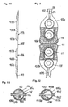
- a carrier 2 has initially four in series and mirror-symmetrically arranged to a bending line 7 wells 3a, 3b; 4a, 4b.
- the components to be mixed with each other are introduced into the two central recesses 3a, 3b.
- only these central recesses 3a, 3b are closed with a film 5 to form two central chambers 3a ', 3b'.
- the closing takes place in such a way that in each case a connecting channel half 8 'remains free by engaging a predetermined breaking point 14 or 15 to the adjacent recesses 4a, 4b.
- the strip-like carrier 2 has the already mentioned transverse to the longitudinal extent of the carrier 2 extending bending line 7.
- the in Fig. 1 Right support section 2b on the in Fig. 1 left support portion 2a can be folded so that it assumes a position as shown in FIG Fig. 2 is shown, in which the two halves of the two recesses 3a, 3b common cover 5 lie on each other.
- the chambers 3a ', 3b' on the one hand and the depressions 4a, 4b are not only arranged at equal distances from the bending line 7, but also designed and dimensioned according to Fig. 2 almost completely coincide or at least one depression completely covers the other.
- predetermined breaking points 14, 15 or in addition to these in the common channel 8
- a further (not shown) predetermined breaking point can be provided, which opens upon exertion of pressure on the two chambers 3a ', 3b'.
- Both in the connecting channel 8 and in the discharge channel 9 may additionally be provided a mixing device.
- the size of the chamber 4 ' is sized or expandable to accommodate all components from the chambers 3a' and 3b '. If all the components are in the chamber 4 ', pressure can be applied to them in the same manner as described above, between the thumb and forefinger of one hand, so that the predetermined breaking point 10 opens and the finished viscous substance from the dispensing channel 9 opens immediately the application site can be expelled.
- Fig. 1 is indicated at the recess 4b by dashed line that this depression can also be omitted. Then the depression 4a forms the mixing chamber 4 'when the carrier sections 2a, 2b are folded on one another.
- Fig. 3 illustrated embodiment corresponds largely to those in the Fig. 1 and 2 is shown.
- the dispensing channel 9 tapers towards its outlet end as a cannula-like applicator 4 "and that a mixing device 13 in the form of a chicane is shown within the dispensing channel 9.
- the chamber 4 'in which inserts 6 correspond FIG. 2 can be arranged, thereby forming a kind of vial, by means of which a precisely metered application of the multicomponent mixture is possible.
- the walls of the applicator 4 may consist of elastically yielding material, so that a pumping effect can be achieved.
- the multicomponent mixture it is also possible to apply the multicomponent mixture to the application site with the aid of a dispensing channel 9, or an applicator channel following it, eg a brush-like applicator.
- the applicator should be welded in a foil or enclosed by a cap. Only when using the inventive Device is then torn open this protective cover, for example. Via a perforation.
- FIG. 4 in a vertical longitudinal section schematically illustrated device 101 for storing and dispensing a viscous substance not shown in the figures is formed from a first foil-like carrier 102 having a recess 103 which is open at the top in the figure.
- a cover film 104 is applied to the carrier 102 in a liquid-tight manner, so that the depression 103 in the carrier 102 forms a closed chamber 105 with the cover film 104.
- an insert 106 is attached from a substantially unyielding material, for example. By gluing.
- the flat surface of the insert 106 is aligned obliquely to the cover 104 and forms an acute angle with this.
- the hermetic connection between the cover film 104 and the carrier 102 takes place, for example, by welding and gluing in the edge region of the carrier and the film, as indicated by reference numeral 107.
- the connection area between the cover film 104 and the carrier 102 is provided with a predetermined breaking point 108 that this opens under increased internal pressure in the chamber 105 and a discharge channel 109 between the carrier and the cover releases. This can be z. B.
- the insert 106 causes the substance contained in the chamber 105 as completely as possible is discharged through the discharge channel 109, wherein the liner 106 pivots during the emptying of the chamber 105 in a position in which its surface is aligned substantially parallel to the cover 104.
- FIG. 5 schematically illustrated in vertical longitudinal section device 101, two recesses 103a and 103b of different sizes are formed in the carrier 102, which together with the cover 104, which closes both recesses 103a and 103b, a first chamber 105a and a second chamber 105b form.
- the cover film 104 is hermetically connected to the carrier 102 by a seal 107, wherein a predetermined breaking point 108 is provided in the connection region between the cover film 104 and the carrier 102 in the region of the dispensing channel 109.
- the two chambers 105a and 105b communicate with each other via a connection channel 110 formed between the cover film 104 and the carrier 102.
- the connecting channel 110 can also be closed with a predetermined breaking point 108, which can be broken by applying pressure to the substances contained in the chambers 105a and 105b, not shown in the figure.
- an insert 106 ' is arranged, which is provided with steps 111a and 111b such that the otherwise flat surface of the insert 106' extends at different angles to the cover film 104.
- an insert 106 is introduced, the flat surface of which extends substantially parallel to the cover film 104.
- a substance contained in the chamber 105a which may be different or equal to the substance contained in the chamber 105b, can be transferred into the chamber 105b in the manner described above, for example by pressing on the forefinger and thumb of one hand Recess 103a and the recess 103a opposite portion of the cover 104 is applied.
- the insert 106 Upon further compression of the depression 103b against the covering film 104, the insert 106 'pivots further in the direction of the covering film 104, until initially the second step 111b and then also the region of the insert 106' which lies on the right in the figure lies against the covering film 104 and the chamber 105b is thus largely emptied.
- the substances mixed with one another are discharged together from the device 101 via the dispensing channel 109, with the predetermined breaking point 108 being broken.
- two recesses 103a and 103b of substantially the same size and shape are provided in the sheet-like carrier 102.
- two regions 102a and 102b of the carrier 102 can be folded on one another in such a way that the depressions 103a and 103b are substantially opposite one another.
- One or both of the recesses 103a and 103b can thereby be closed by preferably two covering films or two sections of a common covering film folded over one another or, as shown in the figure, by a single, common covering film 104, in order to accommodate two mutually opposite chambers 105a and 105b form.
- the two regions 102a and 102b form therebetween a dispensing channel 109, which is closed by a predetermined breaking point 108.
- inserts 106 are respectively arranged such that their surfaces form an acute angle to each other and to the cover film 104. The surfaces of the inserts 106 thereby move away from each other in the direction of the discharge channel 109.
- the substances contained in the chambers 105a and 105b can be simultaneously discharged from the device 101 through the dispensing passage 109 when pressure is applied to the two opposing depressions 103a and 103b in the carrier 102.
- a mixing device 113 with an inner mixing helix 113a is attached to the dispensing channel 109.
- the mixing device serves at the same time as an applicator for applying the substance (s).
- the mixed helix can also be inserted into any applicator deviating from the figure or directly into the dispensing channel 109.
- FIG. 7 Figure 3 shows schematically in vertical longitudinal section another embodiment of the device 101 for storing and dispensing viscous substances, in which two recesses 103a and 103b of substantially equal size and shape are formed in the carrier 102.
- two support sections 102a and 102b are folded towards each other.
- the depressions 103a and 103b are hermetically sealed by a seal 107 via a respective cover film 104a or 4b, so that two chambers 105a and 105b form in the depressions 103a and 103b.
- a dispensing passage 109 extending from the chambers 105a or 105b in the direction of the bending line 112 is formed, which is closed by predetermined breaking points 108.
- the cover foils 104a and 104b abut one another in the region of the bending line 112 such that the two discharge passages of the chambers 105a and 105b are continued to the left between the cover foils 104a and 104b in the figure.
- a mixing device 113 (applicator) with a Mischhelix 113a is inserted or plugged.
- the support portions 102a and 102b are further pivoted toward each other, so that the recesses 103a and 103b, in each of which a deposit 106, abut one another, the predetermined breaking points 108 in the discharge channel 109 are pierced by the pressure building up in the chambers 105a and 105b, so that the substances contained in the chambers 105a and 105b, respectively, through the discharge channel 109 and the mixing device 113 from the Device 101 are discharged.
- the mixing helix 113a of the mixing device 113 the substances discharged from the chambers 105a and 105b, respectively, which may be identical or different, are mixed together.
- the mixing device 113 is, as shown schematically in the enlarged sectional view of Fig. 8 represented, formed of a cylindrical body with a central through-hole 113b, in which also the Mischhelix 113a is received. Further, in the mixing device 113, two opposed radial grooves 114 are provided, which extend from the edge of the bore 113b to near the outer wall of the mixing device. The dimensions of the grooves 114 and the throughbore 113b are selected so that in each case two superimposed portions of the carrier 102 or the cover 104 can be received in each of the grooves, while the discharge channel 109 is preferably held sealingly in the through hole 113b.
- the configuration and arrangement of the inserts 106 or 106 'in the depressions 103, 103a or 103b of the device 101 can be adapted as a function of the requirements for the application of the substances contained in the chambers 105, 105a or 105b. So it is, for example, possible, all deposits 106 with their surface obliquely or parallel to the cover 104 to align. Furthermore, one or more steps 111 may also be provided in the insert 106 'in order to dispense defined quantities of the viscous substances out of the chambers.
- a z. B. brush-type applicator 115 may be provided in the discharge channel 109 or arranged following this.
- the applicator is welded in a foil or enclosed by a cap 116 which is separable from the carrier 102 along a perforation 117. Only when using the device according to the invention then serving as a protective cover cap 116 is opened or closed, so that the exiting the Ausbringkanal 109 substance with the applicator 115, for example, can be applied to a tooth.
- a z. B. brush-type applicator 115 may be provided in the discharge channel 109 or arranged following this.
- the applicator is welded in a foil or enclosed by a cap 116 which is separable from the carrier 102 along a perforation 117. Only when using the device according to the invention then serving as a protective cover cap 116 is opened or closed, so that the exiting the Ausbringkanal 109 substance with the applicator 115, for example, can be applied to a
- the support portions 102a and 102b may be folded along the lines of weakness 118 such that the recesses 103a and 103b rest on the recesses 103c and 103d, respectively.
- the recesses 103b and 103d two in Fig. 9 Roughened hatched illustrated cover sheets 104 arranged 104, while the recesses 103 a and 103 c form a common chamber.
- FIG. 11 Another embodiment of the inserts 106 is shown in FIG. 11 shown schematically.
- cooperating inserts 106a, 106b are provided, one of which is provided with a locking bar 119 with locking elements 119a and the other with a corresponding bore 120. If the inserts 106a, 106b are pressed against each other, a resistance is to be felt or a noise is heard when engaging the locking elements 119a in the bore 120, so that the user recognizes that a defined amount of the substance has been discharged. In this way, a dosage of even very small amounts of substance to be delivered is possible, as is required, for example, in the case of dental bleaching material.
- FIG. 12 also be provided with a plurality of projections 119 'and corresponding recesses 120' to facilitate the dosing of the substance to be discharged. Also in this embodiment, upon engagement of the projections 119 'in the recesses 120', a resistance is felt or a sound is heard, so that the user recognizes that a defined amount of the substance has been discharged.
- the projections 119 'in the recesses 120' are preferably arranged to each other such that between the engagement of two adjacent projections 119 'in the wells 120', the same volume is discharged.
- the chambers 105a and 105b may be used in the embodiments according to FIGS 11 or 12 be separated from each other by one or more cover sheets, not shown. These cover sheets are pierced by the locking bar 119 and the projections 19 'when the inserts 106a, 106b are pressed against each other.
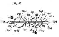
- a further embodiment is shown, which has four recesses 103a to 103d and correspondingly four chambers 105a to 105d in two carrier sections folded along the bending line 112.
- the chambers are closed by cover films 104a and 104b, which are each sealed by a peripheral seal 107 with predetermined breaking points 108 relative to the support sections. If in the chambers 105b and 105d z. B. viscous substances are added, they can be introduced by pressure in the serving as a mixing chamber chamber 105 a. In this case, the predetermined breaking points 108 of the seal 107 are severed, so that a connecting channel 110 is formed between the chambers 105a, 105b and 105d. On the in the Figure lower side of the cover 104b is provided in the seal 107 no predetermined breaking point, so that the chamber 105c remains sealed against the connecting channel 110.
- a mixing ball 121 is provided, with which the substances can be mixed by shaking.
- the chamber 105c opposite this chamber 105a is designed such that the mixing ball 121 can be pressed into the chamber 105c by the covering film.
- This embodiment of the chamber 105c shown may also be substantially the size of the remaining chambers 105a, 105b and 105d and be provided with an insert, in which the mixing ball 121 can be accommodated when the chamber 105a is to be emptied.
- a plurality of mixing balls 121 may be provided in the chamber 105a.
- the chamber 105c or an inlay arranged in this case is then preferably designed to receive a plurality of balls.
Claims (11)
- Dispositif pour le stockage et l'application de substances visqueuses, avec un support par exemple du genre feuille (2, 102), dans lequel sont formés au moins deux renfoncements (3a, 3b ; 4a, 4b ; 103, 103a, 103b, 103c, 103d) ouverts d'un côté, de sorte qu'au moins une substance est introduite dans les renfoncements (3a, 3b ; 4a, 4b ; 103, 103a, 103b, 103c, 103d), puis recouverte par une feuille couvrante (5, 104, 104a, 104b) qui l'isole de l'extérieur en formant des chambres (3a', 3b' ; 105, 105a, 105b, 105c, 105d), de manière à ce qu'il demeure un canal de sortie (9, 109) s'ouvrant lors de l'application d'une pression à au moins l'une des chambres (3a', 3b' ; 105, 105a, 105b, 105c, 105d), par une zone de rupture prédéfinie (14a, 14b ; 108), permettant ainsi d'appliquer la substance visqueuse sortant du canal de sortie (9 ; 109) sur un support d'application,
et avec un applicateur (115) pour les substances s'écoulant à travers le canal de sortie (9 ; 109), l'applicateur (115) étant inséré dans le canal de sortie (9 ; 109) ou alors enfoncé sur celui-ci,
caractérisé en ce que l'applicateur (115) est soudé dans un film ou entouré d'un capuchon. - Dispositif selon la revendication 1, caractérisé en ce que l'applicateur (115) est un pinceau.
- Dispositif selon l'une des revendications 1 ou 2, caractérisé en ce que l'applicateur (115) est un tube applicateur.
- Dispositif selon l'une des revendications précédentes, caractérisé en ce que le canal de sortie (9 ; 109) est constitué en se rétrécissant vers son extrémité de sortie à la manière d'une canule.
- Dispositif selon l'une des revendications précédentes, caractérisé en ce que la chambre (4') accueillant le mélange des composants est conçue comme un applicateur (4") du genre fiole.
- Dispositif selon la revendication 5, caractérisé en ce que les parois de l'applicateur du genre fiole (4") sont conçues de manière élastiquement flexible au moins par endroits.
- Dispositif selon l'une des revendications précédentes, caractérisé en ce que plusieurs renfoncements (103a, 103b) sont prévus côte à côte dans le support (102) pour la formation des chambres (105a, 105b, 105c, 105d), qui sont reliées à un canal de sortie (109) par le biais d'un canal de liaison (110) entre elles.
- Dispositif selon l'une des revendications 1 à 6, caractérisé en ce que plusieurs renfoncements (103a, 103b) sont prévus les uns derrière les autres dans le support (102) pour la formation des chambres (105a, 105b, 105c, 105d), qui sont reliées à un canal de sortie (109) par le biais d'un canal de liaison entre elles (110).
- Dispositif selon l'une des revendications 7 ou 8, caractérisé en ce que les chambres (105a, 105b, 105c, 105d) sont reliées à un canal de sortie (109), par le biais d'un canal de liaison (110) s'ouvrant lors de l'application d'une pression sur chacune des chambres (105a, 105b, 105c, 105d), par une zone de rupture prédéfinie (108).
- Dispositif selon l'une des revendications 7 à 9, caractérisé en ce que par un pliage du support (102), les renfoncements correspondants se retrouvent pliés les uns sur les autres, de telle manière que les feuilles couvrantes (104 ; 104a, 104b) recouvrant les chambres (105a, 105b, 105c, 105d) ou encore les renfoncements (103, 103a, 103b, 103c, 103d) dans le support (102) sont essentiellement superposés.
- Dispositif selon l'une des revendications précédentes, caractérisé en ce que dans un canal de liaison (8 ; 8a, 8b ; 110) prévu entre les chambres et/ou dans le canal de sortie (9, 109), se trouve un dispositif de mélange (13 ; 113a) pour les substances qui le traversent.
Priority Applications (1)
| Application Number | Priority Date | Filing Date | Title |
|---|---|---|---|
| EP09006896.6A EP2092909B1 (fr) | 2002-11-02 | 2003-10-23 | Dispositif de stockage et de sortie de substances visqueuses |
Applications Claiming Priority (5)
| Application Number | Priority Date | Filing Date | Title |
|---|---|---|---|
| DE10251050A DE10251050B3 (de) | 2002-11-02 | 2002-11-02 | Vorrichtung zum Lagern und Ausbringen viskoser Substanzen |
| DE10251050 | 2002-11-02 | ||
| DE20309546U | 2003-06-20 | ||
| DE20309546U DE20309546U1 (de) | 2002-11-02 | 2003-06-20 | Vorrichtung zum Lagern und Ausbringen viskoser Substanzen |
| PCT/EP2003/011719 WO2004041107A2 (fr) | 2002-11-02 | 2003-10-23 | Dispositif de stockage et d'application de substances visqueuses |
Related Child Applications (1)
| Application Number | Title | Priority Date | Filing Date |
|---|---|---|---|
| EP09006896.6A Division EP2092909B1 (fr) | 2002-11-02 | 2003-10-23 | Dispositif de stockage et de sortie de substances visqueuses |
Publications (2)
| Publication Number | Publication Date |
|---|---|
| EP1555952A1 EP1555952A1 (fr) | 2005-07-27 |
| EP1555952B1 true EP1555952B1 (fr) | 2009-07-08 |
Family
ID=32313539
Family Applications (1)
| Application Number | Title | Priority Date | Filing Date |
|---|---|---|---|
| EP03753565A Expired - Lifetime EP1555952B1 (fr) | 2002-11-02 | 2003-10-23 | Dispositif de stockage et d'application de substances visqueuses |
Country Status (4)
| Country | Link |
|---|---|
| US (2) | US7625114B2 (fr) |
| EP (1) | EP1555952B1 (fr) |
| JP (1) | JP4027390B2 (fr) |
| WO (1) | WO2004041107A2 (fr) |
Families Citing this family (30)
| Publication number | Priority date | Publication date | Assignee | Title |
|---|---|---|---|---|
| EP1555952B1 (fr) * | 2002-11-02 | 2009-07-08 | Kettenbach GmbH & CO. KG | Dispositif de stockage et d'application de substances visqueuses |
| US20100065582A1 (en) * | 2003-12-02 | 2010-03-18 | The Tapemark Company | Dispensing package |
| EA009500B1 (ru) * | 2004-03-11 | 2008-02-28 | Эподпак Интернейшнл Инк. | Устройство для хранения и выдачи вещества |
| US7374040B2 (en) * | 2004-12-22 | 2008-05-20 | 3M Innovative Properties Company | Devices for storing and dispensing compositions |
| EP1733697B1 (fr) * | 2005-06-15 | 2018-08-29 | DENTSPLY DETREY GmbH | Applicateur pour une composition dentaire liquide |
| US20070138204A1 (en) * | 2005-12-15 | 2007-06-21 | Kimberly-Clark Worldwide, Inc. | Applicator that is used to apply one or more materials to a surface |
| US9095399B2 (en) | 2008-01-23 | 2015-08-04 | 3M Innovative Properties Company | Dental package, and method of making the package |
| DE202008008423U1 (de) | 2008-06-25 | 2008-10-16 | Kettenbach Gmbh & Co. Kg | Aufreißbare Verpackung |
| DE102009029941A1 (de) * | 2008-06-25 | 2010-01-07 | Kettenbach Gmbh & Co. Kg | Aufreißbare Verpackung |
| US7984831B2 (en) * | 2008-10-23 | 2011-07-26 | Gojo Industries, Inc. | Handheld dispensers for personal use |
| US8365946B2 (en) * | 2008-11-20 | 2013-02-05 | Inoflate, Llc | Device with expandable chamber for pressurizing containers |
| WO2010109610A1 (fr) * | 2009-03-25 | 2010-09-30 | 株式会社モリモト医薬 | Conteneur de composition pharmaceutique |
| US8302487B2 (en) * | 2010-03-18 | 2012-11-06 | Samuel Manu-Tech Inc. | Multi-staged audible/ visible indicator for progressive overload condition |
| BR112012032770A2 (pt) | 2010-06-23 | 2016-12-20 | Gambro Lundia Ab | preparação de solições médicas a partir de material em pó |
| DE102010033015B4 (de) * | 2010-07-31 | 2016-03-17 | Gaplast Gmbh | Einmal-Applikator |
| EP2637933B1 (fr) * | 2010-11-10 | 2014-09-10 | Boehringer Ingelheim Microparts GmbH | Procede de remplissage d'un emballage a blister avec un liquide |
| US8556128B2 (en) * | 2010-11-12 | 2013-10-15 | William A. Harper | Dispensing channel pump |
| CN106880493B (zh) * | 2011-01-17 | 2021-03-12 | 阿克蒂夫帕克股份有限公司 | 无菌仓盒和配给器装置 |
| JP5969497B2 (ja) * | 2011-01-17 | 2016-08-17 | アクティヴパック, インコーポレイテッド | 無菌カートリッジおよびディスペンサ装置 |
| FR2971770B1 (fr) * | 2011-02-21 | 2013-03-22 | Eric Noel | Emballage a poche interne dechirable muni d'un moyen de rupture |
| NL2006767C2 (nl) * | 2011-05-11 | 2012-11-13 | Louis Rinze Henricus Adrianus Willemsen | Verpakking voor een fluã¯dum. |
| US10028886B2 (en) | 2011-05-17 | 2018-07-24 | Aktivax, Inc. | Filing system and methods for aseptic cartridge and dispenser arrangement |
| US8806842B1 (en) * | 2011-06-20 | 2014-08-19 | The Packaging Consultants Group | Disposable multiple compartment mixing and dispensing container |
| EP2591748A1 (fr) * | 2011-11-11 | 2013-05-15 | 3M Innovative Properties Company | Dispositif de distribution d'un matériau dentaire et un procédé de distribution |
| DK3248646T3 (da) * | 2016-05-25 | 2021-05-10 | Claudia Mattern | Todelt råemnesæt af plast |
| FR3067911B1 (fr) * | 2017-06-23 | 2019-07-19 | Seb S.A. | Appareil de fabrication d’un produit cosmetique |
| FR3067915B1 (fr) * | 2017-06-23 | 2021-07-23 | Laboratoires M&L | Couple de capsules assemblees ensemble et comprenant respectivement deux phases differentes a melanger |
| FR3085842B1 (fr) * | 2018-09-14 | 2021-01-08 | Laboratoires M&L | Capsule deformable a usage unique contenant un produit cosmetique |
| CN216738259U (zh) * | 2020-06-16 | 2022-06-14 | Zuru(新加坡)私人有限公司 | 一种容器 |
| CN114590480A (zh) * | 2022-03-31 | 2022-06-07 | 淮安赫德兹彩色印刷包装有限公司 | 一种双组份混合式包装袋 |
Family Cites Families (40)
| Publication number | Priority date | Publication date | Assignee | Title |
|---|---|---|---|---|
| US2487236A (en) | 1947-12-31 | 1949-11-08 | Alvin A Greenberg | Compartmented container having a rupturable partition |
| US3266625A (en) * | 1965-07-08 | 1966-08-16 | H V Hardman Co Inc | Package for reactive multi-component compositions |
| BE754657Q (fr) * | 1965-11-29 | 1971-01-18 | Kenics Corp | Appareil melangeur |
| US4130245A (en) * | 1977-09-29 | 1978-12-19 | Will Ross, Inc. | Liquid dispensing package |
| DE3122237A1 (de) | 1981-06-04 | 1983-01-05 | Hartmut 7500 Karlsruhe Klocke | Verpackung fuer fluessiges fuellgut |
| US4534509A (en) | 1982-09-28 | 1985-08-13 | Firmenich Sa | Multiple compartment plastic packing |
| DE3310215A1 (de) | 1983-03-21 | 1984-09-27 | Gustav 7407 Rottenburg Flier | Duenne kleinplastikverpackung auch fuer fluessige substanzen mit eingebrachter dosieroeffnung |
| CH670236A5 (fr) | 1986-06-04 | 1989-05-31 | Ivers Lee Ag | |
| FR2602752B1 (fr) | 1986-08-12 | 1988-11-10 | Oreal | Ensemble pour le conditionnement separe d'au moins deux produits ne devant etre mis en contact qu'au moment de l'emploi et pour la realisation de cette mise en contact |
| JPH031419Y2 (fr) | 1987-01-08 | 1991-01-17 | ||
| DE8900469U1 (fr) * | 1989-01-17 | 1990-05-23 | Espe Stiftung & Co Produktions- Und Vertriebs Kg, 8031 Seefeld, De | |
| US5240415A (en) | 1990-06-07 | 1993-08-31 | Haynie Michel B | Dental bleach system having separately compartmented fumed silica and hydrogen peroxide and method of using |
| US5287961A (en) * | 1992-10-23 | 1994-02-22 | W.R. Grace & Co.-Conn. | Multi-compartment package having improved partition strip |
| DE9307726U1 (fr) | 1993-05-21 | 1993-07-29 | Klocke Verpackungs-Service Gmbh, 76356 Weingarten, De | |
| US5660273A (en) | 1994-07-13 | 1997-08-26 | Centrix, Inc. | Single patient dose medicament dispenser with applicator |
| DE29714246U1 (de) | 1997-08-08 | 1998-12-10 | Thera Ges Fuer Patente | Vorrichtung zum Lagern und Auftragen einer fließfähigen Substanz |
| JPH11227843A (ja) * | 1998-02-13 | 1999-08-24 | Shiseido Co Ltd | アルミパウチ混合容器 |
| DE29821193U1 (de) * | 1998-11-26 | 2000-03-30 | Espe Dental Ag | Mischkapsel |
| US6135632A (en) * | 1999-06-16 | 2000-10-24 | Flint; Theodore R. | Disposable static mixing device having check valve flaps |
| AU8006200A (en) | 1999-10-08 | 2001-04-23 | Procter & Gamble Company, The | Applicator having a temperature changing element for distributing a product ontoa target surface |
| DE29921427U1 (de) | 1999-12-06 | 2000-02-10 | Rpc Bramlage Gmbh | Mehrkomponenten-Behälter zur Aufbewahrung und zum Ausbringen von flüssigen bis pastösen Stoffen |
| DE19962436B4 (de) | 1999-12-22 | 2005-05-25 | 3M Espe Ag | Verfahren zum Ausbringen einer fließfähigen Substanz aus einer Verpackung |
| DE10007581C2 (de) | 2000-02-21 | 2003-05-28 | 3M Espe Ag | Mischkapsel, Verfahren zu ihrer Herstellung und deren Verwendung |
| DE10009623B4 (de) * | 2000-03-01 | 2005-08-11 | 3M Espe Ag | Vorrichtung zum Lagern und Ausbringen einer fließfähigen Substanz und Verwendung dieser Vorrichtung |
| EP1286899B1 (fr) * | 2000-05-10 | 2004-12-22 | 3M Espe AG | Dispositif pour stocker et melanger des matieres pateuses |
| DE10034647C1 (de) | 2000-07-14 | 2002-04-04 | 3M Espe Ag | Verfahren zur Durchführung einer Speichelanalyse |
| DE10056212B4 (de) | 2000-11-13 | 2005-08-18 | 3M Espe Ag | Vorrichtung zum Lagern und Ausbringen von fließfähigen Zusammensetzungen, Verfahren zur Herstellung und Verwendung der Vorrichtung |
| US6612769B2 (en) | 2000-12-13 | 2003-09-02 | Innovative Properties Company | Package and dispensing actuator for multiple-component compositions |
| DE20111705U1 (de) | 2001-07-19 | 2001-09-27 | Klocke Verpackungs Service | Mehrkomponentenpackung |
| US20030047466A1 (en) * | 2001-09-10 | 2003-03-13 | Matthews Alan B. | Unit-dose packaging system |
| DE10243401B4 (de) * | 2002-09-18 | 2004-07-29 | Voco Gmbh | Verpackung zum Lagern von Substanzen und Verfahren zum Herstellen eines direkt applizierbaren Gemisches zweier Substanzen aus dieser Verpackung |
| EP1555952B1 (fr) * | 2002-11-02 | 2009-07-08 | Kettenbach GmbH & CO. KG | Dispositif de stockage et d'application de substances visqueuses |
| WO2005027815A1 (fr) * | 2003-09-18 | 2005-03-31 | Smithkline Beechman Corporation | Methode d'application de preparations orales |
| DE202004014511U1 (de) * | 2004-09-17 | 2004-11-25 | Klocke Verpackungs-Service Gmbh | Mehrkammerverpackung |
| US7357248B2 (en) * | 2004-12-14 | 2008-04-15 | Illinois Tool Works Inc. | Point of use cleaning solution |
| DE202005001203U1 (de) * | 2005-01-26 | 2006-06-14 | Sulzer Chemtech Ag | Mehrkomponentenfolienbehälter |
| US7325703B2 (en) * | 2005-06-16 | 2008-02-05 | R.P. Scherer Technologies, Inc. | Multi-cavity blister package for storing and dispensing flowable substances |
| TWM294500U (en) * | 2005-12-02 | 2006-07-21 | Yung Shin Pharm Ind Co Ltd | Separated double-bag structure enabling easy mixing of its contained medicines, substances, or the likes |
| US20090114677A1 (en) * | 2007-11-05 | 2009-05-07 | Geoffrey Catherwood Stuart | Dual Receptacle Symmetrical Package for Liquids |
| JP5037304B2 (ja) * | 2007-11-09 | 2012-09-26 | 阿蘇製薬株式会社 | 綿棒包装容器 |
-
2003
- 2003-10-23 EP EP03753565A patent/EP1555952B1/fr not_active Expired - Lifetime
- 2003-10-23 US US10/513,897 patent/US7625114B2/en not_active Expired - Fee Related
- 2003-10-23 JP JP2005502099A patent/JP4027390B2/ja not_active Expired - Fee Related
- 2003-10-23 WO PCT/EP2003/011719 patent/WO2004041107A2/fr active Application Filing
-
2009
- 2009-10-16 US US12/589,098 patent/US7887231B2/en not_active Expired - Fee Related
Also Published As
| Publication number | Publication date |
|---|---|
| JP4027390B2 (ja) | 2007-12-26 |
| US20050150904A1 (en) | 2005-07-14 |
| WO2004041107A2 (fr) | 2004-05-21 |
| JP2006504594A (ja) | 2006-02-09 |
| US7625114B2 (en) | 2009-12-01 |
| US7887231B2 (en) | 2011-02-15 |
| US20100039882A1 (en) | 2010-02-18 |
| EP1555952A1 (fr) | 2005-07-27 |
Similar Documents
| Publication | Publication Date | Title |
|---|---|---|
| EP1555952B1 (fr) | Dispositif de stockage et d'application de substances visqueuses | |
| DE10056212B4 (de) | Vorrichtung zum Lagern und Ausbringen von fließfähigen Zusammensetzungen, Verfahren zur Herstellung und Verwendung der Vorrichtung | |
| DE60112323T2 (de) | Verpackung für mehrkomponentenzusammensetzungen | |
| DE60219567T2 (de) | Abgabevorrichtung für Artzneimittel in Einzeldosen mit Applikator | |
| EP2085322B1 (fr) | Emballage destiné à stocker une substance fluide, pâteuse ou poudreuse et procédé de stockage et d'application de la substance | |
| DE69533528T2 (de) | Abgabevorrichtung für Arzneimittel in Einzeldosen mit Applikator | |
| DE102007005830B3 (de) | Verpackung zur getrennten Aufbewahrung von Lebensmitteln und Verfahren zur Anwendung der Verpackung | |
| DE10243401B4 (de) | Verpackung zum Lagern von Substanzen und Verfahren zum Herstellen eines direkt applizierbaren Gemisches zweier Substanzen aus dieser Verpackung | |
| EP1240087B1 (fr) | Dispositif pour stocker et distribuer une substance coulante | |
| EP1259440B1 (fr) | Dispositif de stockage et d'administration de substances | |
| EP2510897B1 (fr) | Capsule de mélange et d'application pour la fabrication d'une préparation dentaire | |
| WO2011035449A2 (fr) | Contenant scellé pourvu d'un piston coulissant | |
| EP2277800B1 (fr) | Dispositif destiné au stockage et au dosage de plusieurs composants | |
| WO2006094483A1 (fr) | Emballage pour plusieurs composants comprenant un applicateur | |
| EP3171925B1 (fr) | Tube avec embout applicateur | |
| EP2871136A1 (fr) | Récipient destiné à la distribution dosée d'un liquide et un système de conditionnement doté d'un tel récipient | |
| EP1609739B1 (fr) | Article distributeur à usage unique et procédé de fabrication d'un article distributeur à usage unique | |
| EP2092909B1 (fr) | Dispositif de stockage et de sortie de substances visqueuses | |
| DE202004000591U1 (de) | Wiederverschließbare Verpackung für flüssige und pastöse Medien | |
| WO2001085569A1 (fr) | Dispositif pour stocker et melanger des matieres pateuses | |
| DE3416083A1 (de) | Verpackung fuer verwendungsportionen von plastischer zahnfuellmasse | |
| DE10047679C2 (de) | Vorrichtung zum Lagern und Mischen von pastösen Massen und deren Verwendung | |
| EP1947028A2 (fr) | Dispositif destiné au stockage et au dosage de plusieurs composants | |
| EP2277801A1 (fr) | Dispositif destiné au stockage et au dosage de plusieurs composants | |
| EP2920082B1 (fr) | Récipient pour la distribution d'une matière adhésive sous forme d'un mélange à plusieurs constituants |
Legal Events
| Date | Code | Title | Description |
|---|---|---|---|
| PUAI | Public reference made under article 153(3) epc to a published international application that has entered the european phase |
Free format text: ORIGINAL CODE: 0009012 |
|
| 17P | Request for examination filed |
Effective date: 20040423 |
|
| AK | Designated contracting states |
Kind code of ref document: A1 Designated state(s): AT BE BG CH CY CZ DE DK EE ES FI FR GB GR HU IE IT LI LU MC NL PT RO SE SI SK TR |
|
| 17Q | First examination report despatched |
Effective date: 20050823 |
|
| GRAP | Despatch of communication of intention to grant a patent |
Free format text: ORIGINAL CODE: EPIDOSNIGR1 |
|
| GRAS | Grant fee paid |
Free format text: ORIGINAL CODE: EPIDOSNIGR3 |
|
| GRAA | (expected) grant |
Free format text: ORIGINAL CODE: 0009210 |
|
| AK | Designated contracting states |
Kind code of ref document: B1 Designated state(s): AT BE BG CH CY CZ DE DK EE ES FI FR GB GR HU IE IT LI LU MC NL PT RO SE SI SK TR |
|
| REG | Reference to a national code |
Ref country code: GB Ref legal event code: FG4D Free format text: NOT ENGLISH |
|
| REG | Reference to a national code |
Ref country code: CH Ref legal event code: NV Representative=s name: SCHMAUDER & PARTNER AG PATENTANWALTSBUERO Ref country code: CH Ref legal event code: EP |
|
| REG | Reference to a national code |
Ref country code: IE Ref legal event code: FG4D |
|
| REG | Reference to a national code |
Ref country code: CH Ref legal event code: PCAR Free format text: SCHMAUDER & PARTNER AG PATENT- UND MARKENANWAELTE VSP;ZWAENGIWEG 7;8038 ZUERICH (CH) |
|
| REF | Corresponds to: |
Ref document number: 50311692 Country of ref document: DE Date of ref document: 20090820 Kind code of ref document: P |
|
| REG | Reference to a national code |
Ref country code: ES Ref legal event code: FG2A Ref document number: 2327402 Country of ref document: ES Kind code of ref document: T3 |
|
| PG25 | Lapsed in a contracting state [announced via postgrant information from national office to epo] |
Ref country code: SI Free format text: LAPSE BECAUSE OF FAILURE TO SUBMIT A TRANSLATION OF THE DESCRIPTION OR TO PAY THE FEE WITHIN THE PRESCRIBED TIME-LIMIT Effective date: 20090708 |
|
| NLV1 | Nl: lapsed or annulled due to failure to fulfill the requirements of art. 29p and 29m of the patents act | ||
| PG25 | Lapsed in a contracting state [announced via postgrant information from national office to epo] |
Ref country code: FI Free format text: LAPSE BECAUSE OF FAILURE TO SUBMIT A TRANSLATION OF THE DESCRIPTION OR TO PAY THE FEE WITHIN THE PRESCRIBED TIME-LIMIT Effective date: 20090708 |
|
| REG | Reference to a national code |
Ref country code: IE Ref legal event code: FD4D |
|
| PG25 | Lapsed in a contracting state [announced via postgrant information from national office to epo] |
Ref country code: NL Free format text: LAPSE BECAUSE OF FAILURE TO SUBMIT A TRANSLATION OF THE DESCRIPTION OR TO PAY THE FEE WITHIN THE PRESCRIBED TIME-LIMIT Effective date: 20090708 |
|
| PG25 | Lapsed in a contracting state [announced via postgrant information from national office to epo] |
Ref country code: PT Free format text: LAPSE BECAUSE OF FAILURE TO SUBMIT A TRANSLATION OF THE DESCRIPTION OR TO PAY THE FEE WITHIN THE PRESCRIBED TIME-LIMIT Effective date: 20091109 Ref country code: BG Free format text: LAPSE BECAUSE OF FAILURE TO SUBMIT A TRANSLATION OF THE DESCRIPTION OR TO PAY THE FEE WITHIN THE PRESCRIBED TIME-LIMIT Effective date: 20091008 |
|
| BERE | Be: lapsed |
Owner name: KETTENBACH G.M.B.H. & CO. KG Effective date: 20091031 |
|
| PG25 | Lapsed in a contracting state [announced via postgrant information from national office to epo] |
Ref country code: DK Free format text: LAPSE BECAUSE OF FAILURE TO SUBMIT A TRANSLATION OF THE DESCRIPTION OR TO PAY THE FEE WITHIN THE PRESCRIBED TIME-LIMIT Effective date: 20090708 Ref country code: CZ Free format text: LAPSE BECAUSE OF FAILURE TO SUBMIT A TRANSLATION OF THE DESCRIPTION OR TO PAY THE FEE WITHIN THE PRESCRIBED TIME-LIMIT Effective date: 20090708 Ref country code: IE Free format text: LAPSE BECAUSE OF FAILURE TO SUBMIT A TRANSLATION OF THE DESCRIPTION OR TO PAY THE FEE WITHIN THE PRESCRIBED TIME-LIMIT Effective date: 20090708 Ref country code: RO Free format text: LAPSE BECAUSE OF FAILURE TO SUBMIT A TRANSLATION OF THE DESCRIPTION OR TO PAY THE FEE WITHIN THE PRESCRIBED TIME-LIMIT Effective date: 20090708 Ref country code: EE Free format text: LAPSE BECAUSE OF FAILURE TO SUBMIT A TRANSLATION OF THE DESCRIPTION OR TO PAY THE FEE WITHIN THE PRESCRIBED TIME-LIMIT Effective date: 20090708 |
|
| PLBE | No opposition filed within time limit |
Free format text: ORIGINAL CODE: 0009261 |
|
| STAA | Information on the status of an ep patent application or granted ep patent |
Free format text: STATUS: NO OPPOSITION FILED WITHIN TIME LIMIT |
|
| PG25 | Lapsed in a contracting state [announced via postgrant information from national office to epo] |
Ref country code: MC Free format text: LAPSE BECAUSE OF NON-PAYMENT OF DUE FEES Effective date: 20091031 Ref country code: SK Free format text: LAPSE BECAUSE OF FAILURE TO SUBMIT A TRANSLATION OF THE DESCRIPTION OR TO PAY THE FEE WITHIN THE PRESCRIBED TIME-LIMIT Effective date: 20090708 |
|
| 26N | No opposition filed |
Effective date: 20100409 |
|
| PG25 | Lapsed in a contracting state [announced via postgrant information from national office to epo] |
Ref country code: GR Free format text: LAPSE BECAUSE OF FAILURE TO SUBMIT A TRANSLATION OF THE DESCRIPTION OR TO PAY THE FEE WITHIN THE PRESCRIBED TIME-LIMIT Effective date: 20091009 Ref country code: BE Free format text: LAPSE BECAUSE OF NON-PAYMENT OF DUE FEES Effective date: 20091031 |
|
| PG25 | Lapsed in a contracting state [announced via postgrant information from national office to epo] |
Ref country code: AT Free format text: LAPSE BECAUSE OF NON-PAYMENT OF DUE FEES Effective date: 20091023 |
|
| PG25 | Lapsed in a contracting state [announced via postgrant information from national office to epo] |
Ref country code: LU Free format text: LAPSE BECAUSE OF NON-PAYMENT OF DUE FEES Effective date: 20091023 |
|
| PG25 | Lapsed in a contracting state [announced via postgrant information from national office to epo] |
Ref country code: HU Free format text: LAPSE BECAUSE OF FAILURE TO SUBMIT A TRANSLATION OF THE DESCRIPTION OR TO PAY THE FEE WITHIN THE PRESCRIBED TIME-LIMIT Effective date: 20100109 |
|
| PG25 | Lapsed in a contracting state [announced via postgrant information from national office to epo] |
Ref country code: TR Free format text: LAPSE BECAUSE OF FAILURE TO SUBMIT A TRANSLATION OF THE DESCRIPTION OR TO PAY THE FEE WITHIN THE PRESCRIBED TIME-LIMIT Effective date: 20090708 |
|
| PG25 | Lapsed in a contracting state [announced via postgrant information from national office to epo] |
Ref country code: CY Free format text: LAPSE BECAUSE OF FAILURE TO SUBMIT A TRANSLATION OF THE DESCRIPTION OR TO PAY THE FEE WITHIN THE PRESCRIBED TIME-LIMIT Effective date: 20090708 |
|
| PG25 | Lapsed in a contracting state [announced via postgrant information from national office to epo] |
Ref country code: SE Free format text: LAPSE BECAUSE OF FAILURE TO SUBMIT A TRANSLATION OF THE DESCRIPTION OR TO PAY THE FEE WITHIN THE PRESCRIBED TIME-LIMIT Effective date: 20090708 |
|
| PGFP | Annual fee paid to national office [announced via postgrant information from national office to epo] |
Ref country code: CH Payment date: 20121024 Year of fee payment: 10 |
|
| PGFP | Annual fee paid to national office [announced via postgrant information from national office to epo] |
Ref country code: ES Payment date: 20121023 Year of fee payment: 10 |
|
| PGFP | Annual fee paid to national office [announced via postgrant information from national office to epo] |
Ref country code: GB Payment date: 20131022 Year of fee payment: 11 |
|
| REG | Reference to a national code |
Ref country code: CH Ref legal event code: PL |
|
| PG25 | Lapsed in a contracting state [announced via postgrant information from national office to epo] |
Ref country code: CH Free format text: LAPSE BECAUSE OF NON-PAYMENT OF DUE FEES Effective date: 20131031 Ref country code: LI Free format text: LAPSE BECAUSE OF NON-PAYMENT OF DUE FEES Effective date: 20131031 |
|
| GBPC | Gb: european patent ceased through non-payment of renewal fee |
Effective date: 20141023 |
|
| REG | Reference to a national code |
Ref country code: ES Ref legal event code: FD2A Effective date: 20150709 |
|
| PG25 | Lapsed in a contracting state [announced via postgrant information from national office to epo] |
Ref country code: ES Free format text: LAPSE BECAUSE OF NON-PAYMENT OF DUE FEES Effective date: 20131024 Ref country code: GB Free format text: LAPSE BECAUSE OF NON-PAYMENT OF DUE FEES Effective date: 20141023 |
|
| REG | Reference to a national code |
Ref country code: FR Ref legal event code: PLFP Year of fee payment: 13 |
|
| PGFP | Annual fee paid to national office [announced via postgrant information from national office to epo] |
Ref country code: IT Payment date: 20151026 Year of fee payment: 13 |
|
| PGFP | Annual fee paid to national office [announced via postgrant information from national office to epo] |
Ref country code: FR Payment date: 20151026 Year of fee payment: 13 |
|
| REG | Reference to a national code |
Ref country code: DE Ref legal event code: R079 Ref document number: 50311692 Country of ref document: DE Free format text: PREVIOUS MAIN CLASS: A61C0005060000 Ipc: A61C0005600000 |
|
| REG | Reference to a national code |
Ref country code: FR Ref legal event code: ST Effective date: 20170630 |
|
| PG25 | Lapsed in a contracting state [announced via postgrant information from national office to epo] |
Ref country code: FR Free format text: LAPSE BECAUSE OF NON-PAYMENT OF DUE FEES Effective date: 20161102 |
|
| PG25 | Lapsed in a contracting state [announced via postgrant information from national office to epo] |
Ref country code: IT Free format text: LAPSE BECAUSE OF NON-PAYMENT OF DUE FEES Effective date: 20161023 |
|
| PGFP | Annual fee paid to national office [announced via postgrant information from national office to epo] |
Ref country code: DE Payment date: 20191023 Year of fee payment: 17 |
|
| REG | Reference to a national code |
Ref country code: DE Ref legal event code: R082 Ref document number: 50311692 Country of ref document: DE Representative=s name: KEIL & SCHAAFHAUSEN PATENTANWAELTE PARTGMBB, DE Ref country code: DE Ref legal event code: R081 Ref document number: 50311692 Country of ref document: DE Owner name: 3LMED GMBH, DE Free format text: FORMER OWNER: KETTENBACH GMBH & CO. KG, 35713 ESCHENBURG, DE |
|
| REG | Reference to a national code |
Ref country code: DE Ref legal event code: R119 Ref document number: 50311692 Country of ref document: DE |
|
| PG25 | Lapsed in a contracting state [announced via postgrant information from national office to epo] |
Ref country code: DE Free format text: LAPSE BECAUSE OF NON-PAYMENT OF DUE FEES Effective date: 20210501 |