EP1555699A2 - Abdeckung für ein Aktorgehäuse und Herstellungsverfahren für eine solche Abdeckung - Google Patents
Abdeckung für ein Aktorgehäuse und Herstellungsverfahren für eine solche Abdeckung Download PDFInfo
- Publication number
- EP1555699A2 EP1555699A2 EP04106604A EP04106604A EP1555699A2 EP 1555699 A2 EP1555699 A2 EP 1555699A2 EP 04106604 A EP04106604 A EP 04106604A EP 04106604 A EP04106604 A EP 04106604A EP 1555699 A2 EP1555699 A2 EP 1555699A2
- Authority
- EP
- European Patent Office
- Prior art keywords
- actuator
- contact
- lid
- cover
- manufacturing
- Prior art date
- Legal status (The legal status is an assumption and is not a legal conclusion. Google has not performed a legal analysis and makes no representation as to the accuracy of the status listed.)
- Granted
Links
Images


Classifications
-
- H—ELECTRICITY
- H10—SEMICONDUCTOR DEVICES; ELECTRIC SOLID-STATE DEVICES NOT OTHERWISE PROVIDED FOR
- H10N—ELECTRIC SOLID-STATE DEVICES NOT OTHERWISE PROVIDED FOR
- H10N30/00—Piezoelectric or electrostrictive devices
- H10N30/80—Constructional details
- H10N30/87—Electrodes or interconnections, e.g. leads or terminals
- H10N30/875—Further connection or lead arrangements, e.g. flexible wiring boards, terminal pins
-
- H—ELECTRICITY
- H10—SEMICONDUCTOR DEVICES; ELECTRIC SOLID-STATE DEVICES NOT OTHERWISE PROVIDED FOR
- H10N—ELECTRIC SOLID-STATE DEVICES NOT OTHERWISE PROVIDED FOR
- H10N30/00—Piezoelectric or electrostrictive devices
- H10N30/80—Constructional details
- H10N30/88—Mounts; Supports; Enclosures; Casings
-
- H—ELECTRICITY
- H10—SEMICONDUCTOR DEVICES; ELECTRIC SOLID-STATE DEVICES NOT OTHERWISE PROVIDED FOR
- H10N—ELECTRIC SOLID-STATE DEVICES NOT OTHERWISE PROVIDED FOR
- H10N30/00—Piezoelectric or electrostrictive devices
- H10N30/80—Constructional details
- H10N30/88—Mounts; Supports; Enclosures; Casings
- H10N30/886—Additional mechanical prestressing means, e.g. springs
Definitions
- the invention relates to a cover according to the preamble of claim 1 and a manufacturing method for a cover according to the preamble of claim 18.
- Piezoelectric actuators as actuators for injectors used.
- the actuators are either with their electric Connector completely in the cylinder head one Internal combustion engine installed or they will be outside the Cylinder head arranged. In both variants it is necessary to install the actuator in a protective shell to him to protect against damaging influences. This happens through Installing the actuator in a housing that protects the actuator.
- the problem here is, for example, the implementation of necessary for electrical control of the actuator connection contacts through the housing.
- the invention is therefore based on the object, a cover for an actuator housing, with the lowest possible Expense the inside of the actuator as reliable as possible seals. It is a further object of the invention to provide a production process specify with which such coverage can be produced with the least possible effort.
- the object is achieved with a cover according to claim 1. Furthermore, a production method according to claim 18 is suitable, to produce such a cover.
- the invention is based on the technical knowledge that for sealing the actuator housing on the outside of a lid can be used as a preformed molding will be produced.
- the lid can be designed as a disk be, which may have a groove on the edge, or as Disc with a circumferential lowered edge, allowing the edge partially encloses the actuator.
- the lid is made as a preformed molding, so this offers the advantage of having a passage in the lid for an external contact, the electrical control of the Actors allows, can be arranged.
- This implementation can be provided with a seal to seal the passage before the lid is attached to the actuator housing becomes.
- This sealings can be used for their Production of special manufacturing conditions such as need an elevated temperature.
- the production of the Cover or the seal is thus independent of any temperature limits to be considered in connection with the actuator.
- Such temperature limits may be, for example by a silicone compound into which the piezo elements of the piezoelectric actuator, or the Curie temperature the piezoceramic be predetermined.
- the lid By the execution the lid as a preformed molding is it too possible, the lid material on its suitability for installation the seal and its resistance to damaging To optimize environmental influences. Furthermore, the Assembly of a preformed molded part on the actuator housing no complicated injection molding process necessary.
- the lid can for example screwed or welded.
- the lid is at least partially made of metal or ceramics. These materials offer the advantage of a high temperature resistance and high resistance against environmental influences such as engine oil or moisture. Furthermore, they offer the advantage of a high strength.
- the seal for sealing the passage of the external contacts may be a glass seal which is disposed between the external contact and the lid.
- a glass seal offers the advantage of a very good seal, the glass seal preferably having a limiting leak rate of 10 -8 mbar / s.
- a small limit leak rate is advantageous because it prevents ingress of liquids or gases into the actuator space.
- glass seals with a limit leak rate of 10 -11 mbar / s or less may be useful.
- the outer contact is completely enclosed by the glass seal, this offers the advantage that the glass seal simultaneously electrically isolates the outer contact from the cover, which is particularly advantageous when the cover is made of metal.
- the glass seal can be designed as a customized glass-metal feedthrough or as a pressure glass feedthrough.
- glass-to-metal bushings glass and metal parts are used whose coefficients of expansion largely correspond between room temperature and the transformation temperature of the glass. This ensures that the external contact made is melted into the glass and on cooling no mechanical stresses in the fusion arise.
- Adapted glass metal bushings offer, for example, the advantage that a plurality of external contacts can be melted in a passage without great effort, which are electrically isolated from each other by the glass.
- metals and glasses are used whose thermal expansion coefficients are different.
- the coefficient of thermal expansion of the outer cover is higher than that of the fused glass and that of the metallic outer contact.
- the lid may be made of a metal having a thermal expansion coefficient ⁇ of 13x10 -6 1 / K between 20 and 300 ° C. It is also possible, however, to use expansion coefficient between 9x10 -6 1 / K and 18 ⁇ 10 -6 1 / K.
- the expansion coefficient in the same temperature range of the glass and the outer contact should be less, for example between 5x10 -6 1 / K and 9 x 10 -6 1 / K.
- the cover has a fastened to the actuator housing Head plate on.
- the top plate has the advantage that they serve as a carrier for a Bourdon tube of the actuator can, wherein the tube spring, the piezoelectric elements of the actuator opposite can bias the top plate.
- Such a bias is advantageous, since thereby a self-destruction of the piezo elements is prevented.
- in the top plate Headgates ducts arranged to one of the Actuator coming actuator contact for electrical control of the Actuator pass through the top plate. This offers the Advantage that the actuator contact outside the top plate connected to the external contact for contacting the actuator can be.
- the lid with the top plate connected to fix the lid.
- the lid has a pulled down edge or the top plate a pulled up Edge on which the lid is attached so that between the top plate and the lid creates a cavity.
- This cavity offers the advantage of being inside the cavity Components, for example, for contacting or for Operation of the actuator are required, protected against harmful environmental influences can be arranged.
- the top plate is at least partially made Metal or ceramic.
- Metal or ceramics offer the advantage high strength and high resistance against attacks of harmful environmental influences.
- the lid is advantageously welded to the top plate, the lid and the top plate in this case Made of metal.
- a welded joint offers the advantage that it represents a lasting connection that, if it is running around, a secure seal can represent between the lid and the top plate.
- Farther can also be the top plate with the housing of the actuator be welded, which also easily a resistant and comprehensive sealing can be achieved.
- the bourdon tube for applying the bias voltage welded to the top plate.
- This offers the advantage a mechanically resistant and durable connection between the top plate and the Bourdon tube, thereby a bias of the piezo elements of the actuator is possible.
- a central part On the inside of the lid is advantageously a central part arranged, which has a contact bridge.
- the contact bridge offers the advantage that the from Actuator coming actuator contact with the externally accessible External contact can be contacted via the contact bridge and thus an electrical control of the actuator from the outside is possible.
- the contact bridge can with the actuator contact, for example be welded before placing the lid. It However, it is also possible, the contact bridge with a plug contact for the actuator contact, which makes assembly easier would. In contrast, a welded joint has the advantage that they have a reliable fixation of the contact bridge allows.
- the contact bridge has a plug connection on to the contact bridge with the external contact pluggable electric to contact.
- This has the advantage that the as Preformed prefabricated lid is simply put on, taking the external contacts already mounted in the cover in the connectors be plugged in. This will be an electrical Contacting the contact bridge with the external contact reached. This is because of advantage, since after putting on the Cover the contact bridge from the outside no longer accessible is, if the lid in this position with the actuator housing or the head plate is flush. After placing the lid and inserting the external contacts in the contact connections the lid only has to be sealing with the top plate or the housing of the actuator are connected, for example by a welded joint to seal the actuator to the outside.
- a plurality of external contacts are arranged in the lid, allowing multiple actuator contacts via the contact bridge are electrically contacted with multiple external contacts.
- the two actuator contacts has the advantage that all actuator contacts are electrically controlled from the outside, if at least two external contacts are arranged in the lid.
- more than two external contacts can be arranged be, for example, to one or more thermocouples, which absorb a temperature of the actuator, to the outside to contact.
- the external contacts be marked in color or design to give them the Assign individual actuator contacts after mounting the cover to be able to.
- glass seals in different Colors are executed to mark the external contacts.
- two actuator contacts with the colors red and blue and two more contacts of a thermocouple be marked with the colors green and yellow.
- an electric Be arranged with at least one component the actuator contacts is electrically contacted.
- the electrical component in the protected and sealed area within the lid For example can the electrical component in a space between the lid and the top plate are arranged.
- the electrical contacting of the electrical component with at least one of the actuator contacts may be advantageous if for the operation of the actuator one with the actuator contacts connected electrical component is necessary. That's the way it works
- the two actuator contacts a Piezoactors with a resistor to connect to charge states of the piezoelectric actuator due to thermal changes and external forces in the unused state.
- the device is preferred arranged at the middle part and electrically with the contact bridge contacted. This has the advantage that the electrical component the contact bridge in a compact design within the Cover is arranged.
- the middle part preferably consists partly of an electric insulating material, wherein the contact bridge or the electrical component at least partially in the electric insulating material are embedded.
- the electrically insulating Material may for example be plastic, and also conceivable is to use ceramics. Plastic has the advantage that in the injection molding process with little effort Molded part can be made, in which the contact bridge or the electrical component can be embedded. ceramics has the advantage of higher temperature resistance.
- the middle part preferably has a protruding sleeve from the electrically insulating material, wherein the sleeve engages in the head plate bushing and the actuator contact in the sleeve is passed through the top plate.
- This allows an electrical insulation between Make the actuator contact and the top plate. This has the advantage that it does not over the top plate to one Short circuit of the actuator contact comes. Furthermore, it will the middle part in its position on the top plate inside the lid fixed better. If the sleeve has an outer diameter on, which is essentially equal to the diameter of the Headplate execution is, so this has the advantage that the sleeve completely fills the head plate lead-through, whereby the middle part is better fixed. So can too an additional seal of the interior of the actuator. Should the seal of the lid fail, it would still be another lock exists before liquids or gases could penetrate from the outside into the interior.
- the invention comprises a manufacturing method for Production of the above-described advantageous embodiment.
- the cover is preferably in the cover the bushings drilled, whereby the Lid is made of metal.
- the provided with the bushings Lid is heated, for example to about 300 ° C.
- the mentioned glass seals for the pressure glass passage of the external contacts in the lid used.
- the heated external contacts in Insert the lid with the glass seal and then the lid is cooled with the glass seal and the external contacts, so that the external contact and the glass seal strained remain in the lid.
- the lid is preferably on the top plate put on, with the external contact in the connector is plugged and the lid welded to the top plate becomes. This is on the one hand a contact of the External contact with the actuator contact, at the contact bridge can be welded, guaranteed and continue a seal of the actuator, since both the welded joint as well the pressure load passage damaged the inside opposite Seal environmental influences.
- the invention comprises an actuator with a cover in one of the advantageous embodiments described above.
- An injector for an internal combustion engine the an actuator with a cover in one of the above contains advantageous embodiments, has the advantage that even with damaging environmental influences a reliable Operation is possible.
- the invention comprises an injection system for a Internal combustion engine with one or more of those described above Actuators.
- FIG. 1 shows a cover according to the invention and some parts a covered by the cover piezoelectric actuator in an exploded view.
- a cover 1 In a cover 1 are in two holes two glass seals 2 arranged, in which two external contacts 3 are passed.
- the lid 1 is on a circumferential pulled-up edge of a top plate 4 welded to the welded to an actuator housing, not shown in Figure 1 becomes. Both welds are executed circumferentially, so that a sealed connection between the lid 1 and the top plate 4 and the top plate 4 and the actuator housing is available.
- a middle part 5 is arranged having a contact bridge 6 with two connectors 7.
- the middle part 5 is made by the contact bridge 6 with the two connectors 7 with plastic in Injection molding is overmoulded so that only two connecting lugs the contact bridge 6 and the connectors 7 are accessible.
- the connectors 7 are the external contacts 3 inserted.
- For electrical contact of the Actuators are two actuator contacts 8 through two bushings the top plate 4, which are not shown here, and through two sleeves 9 passed and with the contact bridge. 6 are welded.
- the sleeves 9 are part of the central part. 5
- a tube spring 10 is welded, which the piezo elements of the actuator is biased, wherein the piezoelectric elements held by a support plate 11 become.
- a pressure glass feedthrough is performed, in which the glass seals 2 are used together with the external contacts 3 at a temperature of about 300 ° C in the lid 1 and then cooled.
- the lid 1 has a temperature coefficient in the range between 20 ° C and 300 ° C of 13 x 10 -6 1 / K.
- the glass of the glass seals 2 and the metal of the external contacts 3 have a temperature expansion coefficient of 9 ⁇ 10 -6 1 / K in the temperature range mentioned.
- the lid 1 is welded circumferentially to the top plate 4 in order to achieve a sealed attachment of the lid 1 to the top plate 4.
- an electrical resistance welding a laser welding, a press-it method or a cold welding method can be used.
- an electrical resistance welding with a phase-angle welding current control is used for all welded joints, as this allows a very precise execution of the weld with simple means.
- FIGS. 2A to 2C show three sectional views of FIG shown in exploded view in Figure 1.
- the same reference numerals designate the same components and are not explained here again.
- FIG. 2A is the section A-A shown, the center through the actuator runs and the two actuator contacts 8 cuts.
- FIG. 2B the section B-B is shown, which is 90 ° to the section A-A is rotated relative to the longitudinal axis of the actuator and the actuator centered and the external contacts 3 cuts.
- the longitudinal axis of the actuator is the axis in which the actuator is in operation expands.
- the section shown in Figure 2C is opposite the section A-A and the section B-B in each case by 45 ° with respect the longitudinal axis of the actuator rotated.
- the actuator housing 12 encloses the Bourdon tube 10 and is welded to the top plate 4.
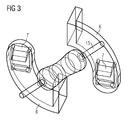
- the resistance 13 is in plastic together with the contact bridge 6 poured and connects via the contact bridge 6, the two Actuator contacts 8.
- FIG. 2C the position of the resistor 13 and the contact bridge is shown 6 in the existing of a plastic extrusion Middle part 5 shown.
- the resistor 13 is connected to the contact bridge 6 welded with its two connecting pins.
- the contact bridge 6 with the resistor 13 in a transparent representation in which only the Edges are shown.
- the resistor 13 is at the contact bridge 6 welded.
- the contact bridge 6 has two tabs on, to which the actuator contacts 8 are welded.
- the contact bridge 6 has two connectors 7 on, in which the external contacts 3 are inserted.
- the contact bridge 6 and the resistor 13 are as in the figures 1 and 2A to 2C shown enclosed in a plastic extrusion.
Landscapes
- Fuel-Injection Apparatus (AREA)
- Motor Or Generator Frames (AREA)
Abstract
Description
- Figur 1
- zeigt eine Explosionsdarstellung einer erfindungsgemäßen Abdeckung mit Teilen eines Aktors, an dem die Abdeckung montiert wird.
- Figuren 2A bis 2C
- zeigen drei Schnittansichten der erfindungsgemäßen Abdeckung mit einem durch die Abdeckung abgedichteten Aktor.
- Figur 3
- zeigt ein Detail der in den anderen Figuren dargestellten erfindungsgemäßen Abdeckung.
Claims (29)
- Abdeckung für ein Aktorgehäuse (12) eines Aktors, insbesondere eines Piezoaktors, mitdadurch gekennzeichnet, dass der Deckel (1) ein vorgeformtes Formteil (1) ist.einem Deckel (1), der das Aktorgehäuse (12) an dessen Außenseite abdichtet,einer in dem Deckel (1) angeordneten Durchführung,einem durch die Durchführung hindurchgeführten Außenkontakt (3), der eine elektrische Ansteuerung des Aktors durch eine externe Steuereinheit ermöglicht, undeiner Dichtung (2) zur Abdichtung der Durchführung, die zwischen dem Deckel (1) und dem Außenkontakt (3) angeordnet ist,
- Abdeckung nach Anspruch 1,
dadurch gekennzeichnet, dass der Deckel (1) mindestens teilweise aus Metall oder Keramik besteht. - Abdeckung nach Anspruch 1 oder 2,
dadurch gekennzeichnet, dass die Dichtung (2) eine Glasdichtung (2) aufweist, die den durchgeführten Außenkontakt (3) zumindest teilweise umschließt, so dass die Durchführung abgedichtet ist. - Abdeckung nach einem der vorangehenden Ansprüche,
dadurch gekennzeichnet, dass der Temperatur-Ausdehnungskoeffizient des Außenkontakts (3) und/oder der Glasdichtung (2) kleiner ist als der des Deckels (1) . - Abdeckung nach einem der vorangehenden Ansprüche,
gekennzeichnet durch
eine an dem Aktorgehäuse (12) befestigbare Kopfplatte (4) mit einer Kopfplatten-Durchführung durch die Kopfplatte (4) für einen von dem Aktor kommenden Aktorkontakt (8), wobei der Deckel (1) mit der Kopfplatte (4) verbunden ist. - Abdeckung nach Anspruch 5,
dadurch gekennzeichnet, dass die Kopfplatte (4) mindestens teilweise aus Metall oder Keramik besteht. - Abdeckung nach Anspruch 5 oder 6,
dadurch gekennzeichnet, dass der Deckel (1) durch eine Schweißverbindung mit der Kopfplatte (4) verbunden ist. - Abdeckung nach einem der Ansprüche 5 bis 7,
dadurch gekennzeichnet, dass der Aktor eine Rohrfeder (10) zur Aufbringung einer Vorspannung aufweist, wobei die Kopfplatte (4) durch eine Schweißverbindung mit der Rohrfeder (10) verbindbar ist. - Abdeckung nach einem der vorangehenden Ansprüche,
gekennzeichnet durch
eine auf der Innenseite des Deckels (1) angeordnetes Mittelteil (5), das eine Kontaktbrücke (6) aufweist, die mit dem Aktorkontakt (8) elektrisch kontaktierbar ist und die mit dem Außenkontakt (3) elektrisch kontaktiert ist. - Abdeckung nach Anspruch 9,
dadurch gekennzeichnet, dass die Kontaktbrücke (6) eine Steckverbindung (7) aufweist, mit welcher der Außenkontakt (3) steckbar elektrisch kontaktiert ist. - Abdeckung nach Anspruch 9 oder 10,
gekennzeichnet durch
mehrere von Außenkontakte (3), so dass mehrere Aktorkontakte (8) durch die Kontaktbrücke (6) mit mehreren Außenkontakten (3) elektrisch kontaktierbar sind. - Abdeckung nach einem der Ansprüche 9 bis 11,
dadurch gekennzeichnet, dass innerhalb des Deckels (1) ein elektrisches Bauelement (13) angeordnet ist, das mit mindestens einem der Aktorkontakte (8) elektrisch kontaktierbar ist. - Abdeckung nach einem der Ansprüche 9 bis 12,
dadurch gekennzeichnet, dass das Mittelteil (5) teilweise aus einem elektrisch isolierenden Material besteht, wobei die Kontaktbrücke (6) und/oder das elektrische Bauelement (13) zumindest teilweise in das elektrisch isolierende Material eingebettet sind. - Abdeckung nach Anspruch 13,
dadurch gekennzeichnet, dass das Mittelteil (5) eine hervorstehende Hülse (9) aus dem elektrisch isolierenden Material aufweist, wobei die Hülse (9) in die Kopfplatten-Durchführung hineingreift und der Aktorkontakt (8) in der Hülse (9) durch die Kopfplatte (4) hindurchgeführt ist, so dass die Hülse (9) eine elektrische Isolierung zwischen dem Aktorkontakt (8) und der Kopfplatte (4) darstellt. - Aktor mit einer Abdeckung nach einem der Ansprüche 1 bis 14.
- Injektor für eine Brennkraftmaschine mit einem Aktor nach Anspruch 15.
- Einspritzanlage für eine Brennkraftmaschine mit einem Injektor nach Anspruch 16.
- Herstellungsverfahren für eine Abdeckung für ein Aktorgehäuse (12) eines Aktors, insbesondere eines Piezoaktors, mit den folgenden Schritten:dadurch gekennzeichnet, dass der Deckel (1) als vorgeformtes Formteil (1) hergestellt wird.Herstellen eines Deckels (1),Anordnen einer Durchführung in dem Deckel (1),Hindurchführen eines Außenkontakts (3), der eine elektrische Ansteuerung des Aktors durch eine externe Steuereinheit ermöglicht, durch die Durchführung des Deckels (1) undAnordnen einer Dichtung (2) zwischen dem Deckel (1) und dem Außenkontakt (3), so dass die Durchführung abgedichtet ist,
- Herstellungsverfahren nach Anspruch 18,
dadurch gekennzeichnet, dass der Deckel (1) zumindest teilweise aus Metall oder Keramik hergestellt wird. - Herstellungsverfahren nach Anspruch 18 oder 19,
dadurch gekennzeichnet, dass als Dichtung (2) eine Glasdichtung (2) angeordnet wird, die den hindurchgeführten Außenkontakt (3) zumindest teilweise umschließt, so dass die Durchführung abgedichtet ist. - Herstellungsverfahren nach einem der Ansprüche 18 bis 20,
dadurch gekennzeichnet, dass der Temperatur-Ausdehnungskoeffizient des Außenkontakts (3) und/oder der Glasdichtung (2) kleiner ist als der des Deckels (1) . - Herstellungsverfahren nach einem der Ansprüche 19 bis 21,
gekennzeichnet durch
die folgenden Schritte:Herstellen einer Kopfplatte (4), die an dem Aktorgehäuse (12) befestigbar ist,Anordnen zweier Kopfplatten-Durchführungen für einen Aktorkontakt (8) undVerbinden des Deckels (1) mit der Kopfplatte (4). - Herstellungsverfahren nach Anspruch 22,
dadurch gekennzeichnet, dass die Kopfplatte (4) mindestens teilweise aus Metall oder Keramik hergestellt wird. - Herstellungsverfahren nach Anspruch 22 oder 23,
dadurch gekennzeichnet, dass der Aktor eine Rohrfeder (10) zur Aufbringung einer Vorspannung aufweist, wobei die Kopfplatte (4) mit der Rohrfeder (10) verschweißt wird. - Herstellungsverfahren nach einem der Ansprüche 18 bis 24,
gekennzeichnet durchAnordnen eines Mittelteils (5) auf der Innenseite des Deckels (1), das eine Kontaktbrücke (6) aufweist undKontaktieren des Aktorkontakts (8) mit dem Außenkontakt (3) über die Kontaktbrücke (6). - Herstellungsverfahren nach Anspruch 25,
dadurch gekennzeichnet, dass die Kontaktbrücke (6) mit einer Steckverbindung (7) ausgerüstet wird, mit welcher der Außenkontakt (3) steckbar elektrisch kontaktiert wird. - Herstellungsverfahren Anspruche 25 oder 26,
dadurch gekennzeichnet, dass innerhalb des Deckels (1) ein elektrisches Bauelement (13) angeordnet wird, das mit mindestens einem der Aktorkontakte (8) elektrisch kontaktiert wird. - Herstellungsverfahren nach einem der Ansprüche 25 bis 27,
dadurch gekennzeichnet, dass das Mittelteil (5) teilweise aus einem elektrisch isolierenden Material hergestellt wird und die Kontaktbrücke (6) und/oder das elektrische Bauelement (13) zumindest teilweise in das elektrisch isolierendes Material eingebettet wird. - Herstellungsverfahren nach einem der Ansprüche 18 bis 28,
gekennzeichnet durch
die folgenden Schritte:Bohren der Durchführungen in den Deckel (1), wobei der Deckel (1) aus Metall besteht,Erwärmen des Deckels (1),Einsetzen der erwärmten Glasdichtung (2) in den Deckel (1) ,Einsetzen des Außenkontakts (3) in den Deckel (1),Abkühlen des Deckels (1) mit der Glasdichtung (2) und dem Außenkontakt (3), so dass der Außenkontakt (3) und die Glasdichtung (2) verspannt in dem Deckel (1) verbleiben,Aufsetzen des Deckels (1) auf die Kopfplatte (4), wobei der Außenkontakt (3) in die Steckverbindung (7) gesteckt wird undAnschweißen des Deckels (1) an der Kopfplatte (4).
Applications Claiming Priority (2)
| Application Number | Priority Date | Filing Date | Title |
|---|---|---|---|
| DE102004001677 | 2004-01-12 | ||
| DE102004001677 | 2004-01-12 |
Publications (4)
| Publication Number | Publication Date |
|---|---|
| EP1555699A2 true EP1555699A2 (de) | 2005-07-20 |
| EP1555699A3 EP1555699A3 (de) | 2006-06-14 |
| EP1555699B1 EP1555699B1 (de) | 2007-11-07 |
| EP1555699B8 EP1555699B8 (de) | 2008-02-13 |
Family
ID=34609525
Family Applications (1)
| Application Number | Title | Priority Date | Filing Date |
|---|---|---|---|
| EP04106604A Expired - Lifetime EP1555699B8 (de) | 2004-01-12 | 2004-12-15 | Abdeckung für ein Aktorgehäuse und Herstellungsverfahren für eine solche Abdeckung |
Country Status (2)
| Country | Link |
|---|---|
| EP (1) | EP1555699B8 (de) |
| DE (1) | DE502004005426D1 (de) |
Cited By (3)
| Publication number | Priority date | Publication date | Assignee | Title |
|---|---|---|---|---|
| EP1865565A1 (de) * | 2006-06-08 | 2007-12-12 | Robert Bosch Gmbh | System zum Betreiben eines piezoelektrischen Elements |
| DE102007001595A1 (de) * | 2007-01-02 | 2008-07-03 | Behr Thermot-Tronik Gmbh | Thermostatisches Betätiungselement und Verfahren zur Herstellung eines Heizelements für ein thermostatisches Betätungselement |
| DE102005039558B4 (de) * | 2005-08-22 | 2015-10-15 | Robert Bosch Gmbh | Anordnung mit einem Piezoaktor und ein Verfahren zu dessen Herstellung |
Family Cites Families (7)
| Publication number | Priority date | Publication date | Assignee | Title |
|---|---|---|---|---|
| US5113108A (en) * | 1988-11-04 | 1992-05-12 | Nec Corporation | Hermetically sealed electrostrictive actuator |
| JP2692396B2 (ja) * | 1991-02-22 | 1997-12-17 | 日本電気株式会社 | 圧電アクチュエータおよびその製造方法 |
| US5243492A (en) * | 1992-08-27 | 1993-09-07 | Coors Ceramics Company | Process for fabricating a hermetic coaxial feedthrough |
| DE19818068A1 (de) * | 1998-04-22 | 1999-10-28 | Siemens Ag | Piezoelektronischer Aktor für einen Stellantrieb |
| DE19844743C1 (de) * | 1998-09-29 | 2000-06-08 | Siemens Ag | Kontaktzungenträger zur Abdichtung und Positionierung von Kontaktstiften |
| DE19940346B4 (de) * | 1999-08-25 | 2018-03-22 | Continental Automotive Gmbh | Piezoaktor mit einer Anschlußvorrichtung |
| DE10205909B4 (de) * | 2002-02-13 | 2005-11-10 | Siemens Ag | Dichtungselement für den Piezoaktor eines Kraftstoff-Einspritzventils |
-
2004
- 2004-12-15 EP EP04106604A patent/EP1555699B8/de not_active Expired - Lifetime
- 2004-12-15 DE DE502004005426T patent/DE502004005426D1/de not_active Expired - Lifetime
Cited By (3)
| Publication number | Priority date | Publication date | Assignee | Title |
|---|---|---|---|---|
| DE102005039558B4 (de) * | 2005-08-22 | 2015-10-15 | Robert Bosch Gmbh | Anordnung mit einem Piezoaktor und ein Verfahren zu dessen Herstellung |
| EP1865565A1 (de) * | 2006-06-08 | 2007-12-12 | Robert Bosch Gmbh | System zum Betreiben eines piezoelektrischen Elements |
| DE102007001595A1 (de) * | 2007-01-02 | 2008-07-03 | Behr Thermot-Tronik Gmbh | Thermostatisches Betätiungselement und Verfahren zur Herstellung eines Heizelements für ein thermostatisches Betätungselement |
Also Published As
| Publication number | Publication date |
|---|---|
| EP1555699B8 (de) | 2008-02-13 |
| EP1555699A3 (de) | 2006-06-14 |
| DE502004005426D1 (de) | 2007-12-20 |
| EP1555699B1 (de) | 2007-11-07 |
Similar Documents
| Publication | Publication Date | Title |
|---|---|---|
| DE19818068A1 (de) | Piezoelektronischer Aktor für einen Stellantrieb | |
| DE2843577A1 (de) | Selbstentlueftende batterie | |
| DE10200507A1 (de) | Elektrischer Anschluss für Kraftstofftank | |
| DE60308909T2 (de) | Kraftstoffeinspritzventil mit elektrischem verbinder | |
| EP1714024B1 (de) | Brennstoffsystemteil mit einer kabeldurchführung | |
| DE19940347B4 (de) | Elektrische Verbindungsvorrichtung zum Aufsetzen auf Anschlußstifte eines elektrischen Bausteins | |
| DE102004042352A1 (de) | Kraftstoffinjektor für eine Brennkraftmaschine | |
| EP1628015B1 (de) | Abdichtungsanordnung eines Piezoaktors eines Kraftstoffinjektors | |
| EP0913882A2 (de) | Verfahren zum Isolieren eines elektrischen Bauteiles | |
| EP1555699B1 (de) | Abdeckung für ein Aktorgehäuse und Herstellungsverfahren für eine solche Abdeckung | |
| DE19940346B4 (de) | Piezoaktor mit einer Anschlußvorrichtung | |
| DE102005017807B4 (de) | Stellantrieb zur Betätigung eines Kraftstoffeinspritzventils, umfassend einen Deckel zur Abdeckung einer Kontaktierungs- und/oder Abdichtungsanordnung | |
| DE19735559A1 (de) | Gasmeßfühler | |
| EP2636082B1 (de) | Verfahren zur herstellung einer aktoreinheit mit einer hülse zur aufnahme eines piezoaktors | |
| DE10253956A1 (de) | Piezoaktorkontaktierung für Einspritzventil und Verfahren zu dessen Herstellung | |
| WO2005112142A1 (de) | Kopfplattenbaugruppe für einen aktor und herstellungsverfahren für einen aktor | |
| DE102005017808B4 (de) | Stellantrieb zur Betätigung eines Kraftstoffeinspritzventils, umfassend einen Deckel zur Abdeckung einer Kontaktierungs-und/oder Abdichtungsanordnung | |
| DE2151092C3 (de) | Stecker für mineralisolierte elektrische Kabel | |
| DE4127968C2 (de) | Hochtemperaturbeständige Leitungsdurchführung für einen Druckbehälter | |
| WO2006018399A1 (de) | Stellantrieb für einen kraftstoffinjektor einer brennkraftmaschine sowie verwendung hierfür | |
| EP3054146B1 (de) | Bauteileverbund und kraftstoffinjektor | |
| DE102010061946A1 (de) | Piezoelektrisches Aktormodul und Brennstoffeinspritzventil | |
| DE2323967A1 (de) | Anschlusstueck fuer einen elektrischen anschluss | |
| DE19715198A1 (de) | Vakuumventil | |
| DE102019103569B4 (de) | Leiterrahmen für eine Batterievorrichtung eines Elektrofahrzeugs |
Legal Events
| Date | Code | Title | Description |
|---|---|---|---|
| PUAI | Public reference made under article 153(3) epc to a published international application that has entered the european phase |
Free format text: ORIGINAL CODE: 0009012 |
|
| AK | Designated contracting states |
Kind code of ref document: A2 Designated state(s): AT BE BG CH CY CZ DE DK EE ES FI FR GB GR HU IE IS IT LI LT LU MC NL PL PT RO SE SI SK TR |
|
| AX | Request for extension of the european patent |
Extension state: AL BA HR LV MK YU |
|
| PUAL | Search report despatched |
Free format text: ORIGINAL CODE: 0009013 |
|
| AK | Designated contracting states |
Kind code of ref document: A3 Designated state(s): AT BE BG CH CY CZ DE DK EE ES FI FR GB GR HU IE IS IT LI LT LU MC NL PL PT RO SE SI SK TR |
|
| AX | Request for extension of the european patent |
Extension state: AL BA HR LV MK YU |
|
| 17P | Request for examination filed |
Effective date: 20060905 |
|
| 17Q | First examination report despatched |
Effective date: 20061023 |
|
| AKX | Designation fees paid |
Designated state(s): DE FR |
|
| GRAP | Despatch of communication of intention to grant a patent |
Free format text: ORIGINAL CODE: EPIDOSNIGR1 |
|
| GRAS | Grant fee paid |
Free format text: ORIGINAL CODE: EPIDOSNIGR3 |
|
| GRAA | (expected) grant |
Free format text: ORIGINAL CODE: 0009210 |
|
| AK | Designated contracting states |
Kind code of ref document: B1 Designated state(s): DE FR |
|
| REF | Corresponds to: |
Ref document number: 502004005426 Country of ref document: DE Date of ref document: 20071220 Kind code of ref document: P |
|
| RAP2 | Party data changed (patent owner data changed or rights of a patent transferred) |
Owner name: SIEMENS VDO AUTOMOTIVE AG |
|
| RAP2 | Party data changed (patent owner data changed or rights of a patent transferred) |
Owner name: VDO AUTOMOTIVE AG |
|
| REG | Reference to a national code |
Ref country code: FR Ref legal event code: TP |
|
| ET | Fr: translation filed | ||
| RAP2 | Party data changed (patent owner data changed or rights of a patent transferred) |
Owner name: CONTINENTAL AUTOMOTIVE GMBH |
|
| PLBE | No opposition filed within time limit |
Free format text: ORIGINAL CODE: 0009261 |
|
| STAA | Information on the status of an ep patent application or granted ep patent |
Free format text: STATUS: NO OPPOSITION FILED WITHIN TIME LIMIT |
|
| 26N | No opposition filed |
Effective date: 20080808 |
|
| REG | Reference to a national code |
Ref country code: FR Ref legal event code: PLFP Year of fee payment: 12 |
|
| REG | Reference to a national code |
Ref country code: FR Ref legal event code: PLFP Year of fee payment: 13 |
|
| REG | Reference to a national code |
Ref country code: FR Ref legal event code: PLFP Year of fee payment: 14 |
|
| PGFP | Annual fee paid to national office [announced via postgrant information from national office to epo] |
Ref country code: FR Payment date: 20181219 Year of fee payment: 15 |
|
| PGFP | Annual fee paid to national office [announced via postgrant information from national office to epo] |
Ref country code: DE Payment date: 20181231 Year of fee payment: 15 |
|
| REG | Reference to a national code |
Ref country code: DE Ref legal event code: R081 Ref document number: 502004005426 Country of ref document: DE Owner name: VITESCO TECHNOLOGIES GMBH, DE Free format text: FORMER OWNER: CONTINENTAL AUTOMOTIVE GMBH, 30165 HANNOVER, DE |
|
| REG | Reference to a national code |
Ref country code: DE Ref legal event code: R119 Ref document number: 502004005426 Country of ref document: DE |
|
| PG25 | Lapsed in a contracting state [announced via postgrant information from national office to epo] |
Ref country code: DE Free format text: LAPSE BECAUSE OF NON-PAYMENT OF DUE FEES Effective date: 20200701 Ref country code: FR Free format text: LAPSE BECAUSE OF NON-PAYMENT OF DUE FEES Effective date: 20191231 |