EP1555580B1 - Steuerungssystem und -verfahren für Blattförderer - Google Patents
Steuerungssystem und -verfahren für Blattförderer Download PDFInfo
- Publication number
- EP1555580B1 EP1555580B1 EP05100247.5A EP05100247A EP1555580B1 EP 1555580 B1 EP1555580 B1 EP 1555580B1 EP 05100247 A EP05100247 A EP 05100247A EP 1555580 B1 EP1555580 B1 EP 1555580B1
- Authority
- EP
- European Patent Office
- Prior art keywords
- feeder
- forming apparatus
- document forming
- control
- stock
- Prior art date
- Legal status (The legal status is an assumption and is not a legal conclusion. Google has not performed a legal analysis and makes no representation as to the accuracy of the status listed.)
- Ceased
Links
- 238000000034 method Methods 0.000 title description 13
- 239000000758 substrate Substances 0.000 claims description 22
- 238000007639 printing Methods 0.000 claims description 16
- 230000000712 assembly Effects 0.000 claims description 2
- 238000000429 assembly Methods 0.000 claims description 2
- 108091008695 photoreceptors Proteins 0.000 description 8
- 230000008569 process Effects 0.000 description 8
- 238000000926 separation method Methods 0.000 description 7
- 238000012546 transfer Methods 0.000 description 6
- 238000005516 engineering process Methods 0.000 description 4
- 238000013461 design Methods 0.000 description 3
- 238000012356 Product development Methods 0.000 description 2
- 238000013459 approach Methods 0.000 description 2
- 239000011248 coating agent Substances 0.000 description 2
- 238000000576 coating method Methods 0.000 description 2
- 238000011161 development Methods 0.000 description 2
- 238000003384 imaging method Methods 0.000 description 2
- 238000001459 lithography Methods 0.000 description 2
- 238000004519 manufacturing process Methods 0.000 description 2
- 108020003175 receptors Proteins 0.000 description 2
- 238000012360 testing method Methods 0.000 description 2
- 230000003247 decreasing effect Effects 0.000 description 1
- 230000001419 dependent effect Effects 0.000 description 1
- 238000010586 diagram Methods 0.000 description 1
- 230000035553 feeding performance Effects 0.000 description 1
- 239000012467 final product Substances 0.000 description 1
- 230000006870 function Effects 0.000 description 1
- 230000008570 general process Effects 0.000 description 1
- 238000010438 heat treatment Methods 0.000 description 1
- 238000007641 inkjet printing Methods 0.000 description 1
- 238000007648 laser printing Methods 0.000 description 1
- 239000000463 material Substances 0.000 description 1
- 238000007645 offset printing Methods 0.000 description 1
- 239000002245 particle Substances 0.000 description 1
- 238000003825 pressing Methods 0.000 description 1
- 238000012545 processing Methods 0.000 description 1
- 239000000047 product Substances 0.000 description 1
- 238000009877 rendering Methods 0.000 description 1
- 230000000007 visual effect Effects 0.000 description 1
Images


Classifications
-
- G—PHYSICS
- G03—PHOTOGRAPHY; CINEMATOGRAPHY; ANALOGOUS TECHNIQUES USING WAVES OTHER THAN OPTICAL WAVES; ELECTROGRAPHY; HOLOGRAPHY
- G03G—ELECTROGRAPHY; ELECTROPHOTOGRAPHY; MAGNETOGRAPHY
- G03G15/00—Apparatus for electrographic processes using a charge pattern
- G03G15/65—Apparatus which relate to the handling of copy material
- G03G15/6502—Supplying of sheet copy material; Cassettes therefor
- G03G15/6511—Feeding devices for picking up or separation of copy sheets
-
- G—PHYSICS
- G03—PHOTOGRAPHY; CINEMATOGRAPHY; ANALOGOUS TECHNIQUES USING WAVES OTHER THAN OPTICAL WAVES; ELECTROGRAPHY; HOLOGRAPHY
- G03G—ELECTROGRAPHY; ELECTROPHOTOGRAPHY; MAGNETOGRAPHY
- G03G15/00—Apparatus for electrographic processes using a charge pattern
- G03G15/50—Machine control of apparatus for electrographic processes using a charge pattern, e.g. regulating differents parts of the machine, multimode copiers, microprocessor control
- G03G15/5016—User-machine interface; Display panels; Control console
- G03G15/502—User-machine interface; Display panels; Control console relating to the structure of the control menu, e.g. pop-up menus, help screens
-
- G—PHYSICS
- G03—PHOTOGRAPHY; CINEMATOGRAPHY; ANALOGOUS TECHNIQUES USING WAVES OTHER THAN OPTICAL WAVES; ELECTROGRAPHY; HOLOGRAPHY
- G03G—ELECTROGRAPHY; ELECTROPHOTOGRAPHY; MAGNETOGRAPHY
- G03G2215/00—Apparatus for electrophotographic processes
- G03G2215/00362—Apparatus for electrophotographic processes relating to the copy medium handling
- G03G2215/00367—The feeding path segment where particular handling of the copy medium occurs, segments being adjacent and non-overlapping. Each segment is identified by the most downstream point in the segment, so that for instance the segment labelled "Fixing device" is referring to the path between the "Transfer device" and the "Fixing device"
- G03G2215/00371—General use over the entire feeding path
Definitions
- the present exemplary embodiment relates generally to an electrophotographic printing system. It finds particular application in conjunction with a sheet feeder control system and method for improving the feeding of copy sheets that accompanies this general process of copying and printing, and will be described with particular reference thereto. However, it is to be appreciated that the present exemplary embodiment is also amenable to other like applications.
- a light image of an original to be copied or printed is typically recorded in the form of a latent electrostatic image upon a photosensitive member, with a subsequent rendering of the latent image visible by the application of electroscopic marking particles, commonly referred to as toner.
- the visual toner image can be either fixed directly upon the photosensitive member or transferred from the member to another support medium or substrate, such as a sheet of plain paper. To render this toner image permanent, the image must be "fixed” or “fused” to the paper, generally by the application of heat and pressure.
- the sheet handling system must feed paper or other media through each process station in a rapid succession in a reliable and dependable manner in order to utilize the full capabilities of the reproduction machine.
- the sheet handling systems must operate flawlessly to virtually eliminate risk of damaging the recording sheets and generate minimum machine shutdowns due to misfeeds or multifeeds.
- a high speed xerography reproduction machine typically includes a feeder assembly for feeding substrates to the image transfer portion of the machine.
- the feeder assembly may employ vacuum corrugated feeder technology, friction retard feeder technology, or shuttle feeder technology.
- the feeder typically has a fixed set of operating parameters. These settings may be the best compromise for feeding most types of substrates, and, as a result, the substrate feeding capability is generally limited to the range that these parameters allow. While this approach may satisfy the needs of general use copying/printing, it limits the range of substrates that can be fed in the production environment where expanded range is needed. Further, many of the users or operators in the production environment typically come from the offset lithography environment, and they are accustomed to "tuning" their machines for the substrates they are running. Offset lithography is the workhorse of printing. Almost every commercial printer employs it. And the quality of the final product is often due to the guidance, expertise and equipment provided by the printer.
- FIG. 1 is an elevational view showing the basic elements of a document forming apparatus incorporating aspects of the exemplary embodiment
- FIG. 2 is a side view illustrating the feeder assembly
- FIG. 3 is a block diagram illustrating the controller
- FIG. 4 illustrates a basic stock library view
- FIG. 5 illustrates a basic stock settings dialog screen
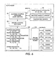
- FIG. 6 is a flow chart of the feeder control process in auto mode
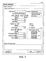
- FIG. 7 illustrates a stock settings dialog screen in accordance with aspects of the exemplary embodiment.
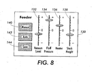
- FIG. 8 illustrates a manual feeder control pop-up screen.
- FIG. 1 there is shown an elevational view of a basic document creating apparatus 10 for creating documents and incorporating aspects of the present exemplary embodiment.
- a basic document creating apparatus 10 for creating documents and incorporating aspects of the present exemplary embodiment.
- a copying or printing system of the type shown is preferably adapted to provide duplex or simplex stacked document sets from duplex or simplex collated document or print sets which result from either duplex or simplex original documents or output document computer files for print.
- the document creating apparatus 10 in the embodiment shown, is a copier. However, in an alternate embodiment, the apparatus could be a printer or any other suitable type of document creating apparatus.
- the apparatus 10 includes a printing engine 12, which includes hardware by which image signals are used to create a desired image, as well as a substrate feeder module 14 , which stores and dispenses substrates (or sheets) upon which images are to be printed, and a finisher 16 , which may include hardware for stacking, folding, stapling, binding, etc., prints which are output from the printing engine 12 .
- a printing engine 12 which includes hardware by which image signals are used to create a desired image
- a substrate feeder module 14 which stores and dispenses substrates (or sheets) upon which images are to be printed
- a finisher 16 which may include hardware for stacking, folding, stapling, binding, etc., prints which are output from the printing engine 12 .
- the feeder 14 is shown as a separate module, it may also be disposed within the printing engine 12 or some other part of the apparatus 10 , as known in the art.
- the apparatus 10 further includes a document feeder 18 , which operates to convert signals from light reflected from original hard-copy image into digital signals, which are in turn processed to create copies with the printing engine 12 .
- the apparatus 10 may also include a local user interface 20 for controlling its operations, although another source of image data and instructions may include any number of computers to which the printer is connected via a network.
- the user interface 20 may include a touch screen for making selections or it can be operated by means of a keyboard and mouse.
- the module includes any number of feeder assemblies 30 , each of which stores print sheets ("stock") of a predetermined type (size, weight, color, coating, transparency, etc.) in a tray and includes a feeder to dispense one of the sheets therein as instructed.
- the feeder may be a shuttle feeder, a vacuum corrugated feeder which utilizes air pressure to feed the sheets or other known types of feeders.
- Such feeders are generally known in the art and are described in various references, including U.S. Patent No. 6,352,255 , U.S. Patent No. 6,264,188 , and U.S. Patent No. 5,356,127 . Certain types of stock may require special handling in order to be dispensed properly.
- heavier or larger stocks may desirably be drawn from a stack by use of an air knife, fluffer, vacuum grip or other application (not shown) of air pressure toward the top sheet or sheets in a stack.
- Certain types of coated stock are advantageously drawn from a stack by the use of an application of heat, such as by a stream of hot air (not shown) or other means. Sheets drawn from a selected tray 30 are then moved to the printing engine 12 to receive one or more images thereon.
- the printing engine 12 is a monochrome xerographic type, although other types of engine, such as color xerographic, ionographic, or ink-jet may be used.
- the printing engine 12 includes a photoreceptor 40 , here in the form of a rotatable belt.
- the photoreceptor 40 is an example of what can be called a "rotatable image receptor,” meaning any rotatable structure such as a drum or belt which can temporarily retain one or more images for printing.
- Such an image receptor can comprise, by way of example and not limitation, a photoreceptor, or an intermediate member for retaining one or more ink or toner layers for subsequent transfer to a sheet, such as in a color xerographic, offset, or ink-jet printing apparatus.
- the photoreceptor 40 is entrained on a number of rollers, and a number of stations familiar in the art of xerography are placed suitably around the photoreceptor 40 , such as a charging station 42 , an imaging station 44 , a development station 46, and a transfer station 48.
- the imaging station 44 is in the form of a laser-based raster output scanner, of a design familiar in the art of "laser printing," in which a narrow laser beam scans successive scan lines oriented perpendicular to the process direction of the rotating photoreceptor 40 .
- the laser is turned on and off to selectably discharge small areas on the moving photoreceptor 40 according to image data to yield an electrostatic latent image, which is developed with toner at the development station 46 and transferred to a sheet at the transfer station 48 .
- a sheet having received an image in this way is subsequently moved through a fuser 50 , of a general design known in the art, and the heat and pressure from the fuser causes the toner image to become substantially permanent on the sheet.
- the printed sheet can then be inverted and re-fed past the transfer station 48 to receive a second-side image.
- the finally-printed sheet is then moved to finisher module 16 , where it may be collated, stapled, folded, etc., with other sheets in methods familiar in the art.
- the substrate feeder module 14 has many control parameters that are "fixed” during the design stage along with some that are variable and controlled through the machine software.
- the variable control parameters include the fluffer air pressure, the vacuum level, whether the air supply heater is on or off, the stack height, and timing. These variables are normally controlled by the printing engine 12 to some pre-set values determined by testing during product development and will be described in greater detail below.
- FIG. 2 there is shown a side elevational schematic view of a basic feeder assembly 30 , incorporating aspects of the present exemplary embodiment.
- the basic components of the feeder assembly 30 include a stack of sheets 52 in a sheet support tray 54 , multiple tray elevators 56, 58 , a stack height sensor 60 , a take away roll 62 , at least one sheet fluffer (or blower) 64 , and a vacuum feed head 66 .
- the feed head 66 includes an acquisition surface 68 .
- the fluffer 64 blows air at the top sheets of paper in the stack 52 . This is done to separate the sheets from the stack 52 and to make them more easily acquired by the feed head 66 .
- the air pressure of the fluffer 64 is typically controlled to a predetermined value.
- the speed of the blower motor 70 for the tray 54 is preset via the brushless DC blower motor input voltage level, while the air flow is metered through a stepper controlled restriction valve (not shown) to different levels. These levels correspond to the levels needed for light to heavy weight paper requirements.
- the substrate feeder module 14 includes a heater (not shown) for preheating the fluffer air and assisting in sheet separation.
- the heater is generally enabled to be turned on and off, since they are only allowed to be "on” if air is not moving through them.
- the substrate feeder module 14 preferably employs shuttle feeder technology, which at a simplified level is merely using vacuum corrugated feeders that physically translate the sheet from the stack to the takeaway rolls.
- the vacuum feed level is a significant feeding control parameter.
- the vacuum may be supplied from individual brushless DC blowers for each feed head 66 .
- the feed vacuum level may be controlled through the vacuum valves.
- the controller 72 may include a media library database 74 (sometimes called a paper/media or substrate catalog as well as stock library), which has a number of memory registers 76 for storing stock (paper) attributes, as well as a feeder capabilities and constraints database 78. It is to be understood, however, that the functions of the two databases 74, 78 may be combined into one database.
- the attributes are generally entered by the user so that the product (feeder) performance can be automatically set for best performance.
- a typical stock library view 80 to the general operator or user is illustrated in FIG. 4 . As shown in that figure, each type of stock may be defined by its size, color, type, and weight, although other stock characteristics may be used.
- a typical stock settings dialog screen 82 is illustrated in FIG. 5 .
- the user may enter all the attributes for the particular stock he or she desires to run. These paper attributes are stored in the memory registers 76 associated with each paper in the stock library.
- Feeder (tray) programming is responsible for programming the paper media attributes of a feeder module or paper tray. Feeder capabilities and constraints are stored in the feeder capabilities and constraints database 78 on the controller 72 .
- the user can now assign a paper from the media library to either a specific paper tray in the printer or simply request that the machine determine which tray the stock is in and automatically feed from that tray. This may be accomplished through the user interface 20.
- the tray elevators 56, 58 will generally lift the top of the stack 52 within a predetermined spacing to the bottom of the feed head 66 (i . e ., the "stack height"), depending on the basis weight input.
- the stack height is generally brought closer to the feed head 66 because its added mass causes it to be levitated less by the fluffer 64 than a light weight sheet.
- a blower will be activated to use a combination of heated air and air pressure, blown into the side of the stack 52 , to separate the uppermost sheets in the stack.
- Fluffers may be on three sides of the stack. Forced air from the fluffer nozzles acts to create an air bearing between the sheets to lower the coefficient of friction between sheets and decrease the chance of multiple feeds.
- the fluffer pressure can be increased or decreased to fine tune the sheet separation for sheet size and weight for a particular stack height setting. For small light papers, fluffer pressures are reduced from nominal. For large heavy sheets, fluffer pressure is increased from nominal.
- Heating elements are placed inside the fluffer duct (not shown) in a high temperature resistant section of the duct. The air is heated to a temperature that is above the temperature inside the module. The heaters are turned on for all coated paper types run regardless of relative humidity to aid in sheet separation.
- the feed head 66 After this preliminary sheet separation occurs, vacuum pressure is applied to the feed head 66 and one or more sheets are pulled up to the bottom of the feed head 66.
- the contour on the acquisition surface 68 ( i . e ., the bottom) of the feed head 66 typically has a corrugation pattern built in, which acts to bend the uppermost sheet in a manner that is difficult for the second sheet to duplicate. After the corrugation pattern has induced areas of separation between the sheets, if multiple sheets were attracted to the feed head 66 , the sheet separation phase begins.
- the fluffer 64 and the feed head corrugation pattern perform initial sheet separation. If both of these methods fail and multiple sheets are still acquired by the feed head, an air knife and fangs (not shown) may be used to separate sheets and retain remaining fluffed sheets.
- the air knife shoots air into the baffle on front of the feed head.
- the baffle reflects that pressure into any air gaps caused by the corrugation pattern to break any bleed through vacuum forces and also down upon the lead edge of the remaining fluffed sheet to retain the stack. This reflection provides localized high pressure areas that occur near the paper stops to prevent remaining sheets from being fed.
- Each feeder 30 has variable air knife pressure settings. For small, light sheets, air knife pressure is reduced from nominal. For large, heavy sheets, air knife pressure is increased from nominal.
- the lead edge 84 of the sheet must move horizontally from above the stack a distance of 16 mm forward to a point 5 mm past the take away roller 62 nip.
- the feed head 66 must move forward and retract within 152 msec.
- the feed head vacuum is turned off when the lead edge 84 of the sheet arrives at the take away roller 62 .
- the air knife will also exert a residual pressure on the lead edge 84 of the sheet.
- the take away roller 62 must overpower this residual feed head vacuum to advance the sheet.
- the residual air knife pressure must be low enough not to force the lead edge 84 of the sheet down during transfer thereby causing paper stop jams or misfeeds.
- the feeder 30 will have different feed rates or feed cycle times, depending on the length of sheet in the process direction, as shown in Table 1 below: TABLE 1 Sheet Length (mm) Sheet Length (in) Feed Rate (pages per minute) Feed Cycle Time (msec) 182-297 >7.17 - 11.7 133 451 298-432 > 11.7 - 17.0 100 600 433 - 470 >17.0 - 18.5 66 909
- the feeder When a sheet of paper is fed, the feeder goes through a cycle up sequence, a feed sequence and then a cycle down sequence. During feeding, the paper location in the paper path is monitored to detect if a jam has occurred.
- the attributes in the paper catalog memory register are read by the machine control software and are used to set the feeder components operation set points.
- the set points are sent to the feeder control board, which in turn controls the feeder elements. This results in the set of operating parameters in auto mode, which is the typical mode of operation of the apparatus 10 .
- FIG. 6 is a flow chart illustrating auto mode for feeder control.
- the inputs include paper catalog attributes 90, relative humidity 92, and temperature 94. These inputs are transmitted to the machine control software 96 for processing.
- the output is then transmitted to the feeder control software 98 to determine the feeder parameters 100 , which include fluffer parameters, heater parameters, feed head vacuum parameters, stack height parameters, timing parameters, and other parameters.
- These parameters 100 are transmitted to the feeder control board 102 , whereby the feeding elements, including fluffer pressure 104 , heater status 106 , vacuum level 108 , stack height 110 , timing 112 , and other elements 114 , as described above, are automatically adjusted.
- the apparatus 10 is typically optimized to be able to feed the widest range of stocks, using a single set of pre-determined control factors or settings. However, a knowledgeable user may be wish to fine tune the system to feed various types of stocks.
- the standard stock settings dialog screen may include a "manual" mode.
- a modified stock settings dialog screen 120 includes an "Expert Feeder Controls" section 122 , containing a "manual" (or “expert") mode operator 124 for making a selection, in addition to an "auto" mode operator 126 . These operators 124, 126 may be activated by means of a mouse and/or keyboard, as well as through a touch screen.
- a control panel pop-up 130 appears so that the user may modify the existing feeder parameters.
- the control panel 130 may be part of the stock settings dialog screen 120 or it can be a separate screen.
- the control panel 130 displays the auto levels for each of the feeder parameters when it is first opened.
- the user has the option of adjusting any of the parameters displayed - such as the vacuum level 132 , the fluff pressure 134 , the heater 136 , and the stack height 138 - to fine tune the feeder performance for the particular stock being run.
- the "manual" indicator 140 stays highlighted during the adjustment process, while the "auto” indicator 142 is not highlighted.
- the user may save these settings by pressing the "save" operator 144 .
- the control panel 130 closes, and the manual mode operator 124 stays highlighted on the stock settings dialog box 120 , indicating that special settings have been made.
- feeder settings When feeder settings are made manually and saved, these settings are appended to the media library database 74 and the feeder capabilities and constraints database 78 so they can be recalled and fed to the controller 72 to modify the feeder parameters whenever this type of stock is run again.
- users save time because they can save the settings once they have been determined so that they can quickly go back to them when they use that stock again.
- the manual mode expands the media range available to users.
- the present exemplary embodiment may also be used to control other aspects of the machine operation affected by the stock, such as fuser temperature increase for rough stock, decurler setting changes for single-side coated stocks.
- the present exemplary embodiment can be used for making adjustments to many different applications within the apparatus 10 .
Landscapes
- Physics & Mathematics (AREA)
- General Physics & Mathematics (AREA)
- Engineering & Computer Science (AREA)
- Human Computer Interaction (AREA)
- Microelectronics & Electronic Packaging (AREA)
- Control Or Security For Electrophotography (AREA)
- Sheets, Magazines, And Separation Thereof (AREA)
- Exposure Or Original Feeding In Electrophotography (AREA)
Claims (5)
- Dokumentenherstellungsvorrichtung, die umfasst:eine Substrat-Zuführeinrichtung, die zum Speichern und Ausgeben von Substraten an einen Drucker eingerichtet ist;eine Steuereinrichtung, die zum Steuern der Funktion der Dokumentenherstellungsvorrichtung eingerichtet ist, wobei die Steuereinrichtung eine Medienbibliothek-Datenbank sowie eine Datenbank mit Fähigkeiten und Beschränkungen der Zuführeinrichtung enthält, die zum Speichern von Informationen für die Funktion der Substrat-Zuführeinrichtung eingerichtet ist;eine Benutzerschnittstelle, die zum Steuern der Funktion der Dokumentenherstellungs-Vorrichtung eingerichtet ist, wobei die Benutzerschnittstelle eine Druckmaterial-Bibliotheks-Ansicht, einen Druckmaterial-Einstellungsdialog-Bildschirm, der einen Experten-Zuführeinrichtungs-Steuerabschnitt mit einem Bedienelement für einen manuellen Modus sowie einem Bedienelement für einen automatischen Modus aufweist und einen Bedienfeld-Bildschirm für Betätigung im manuellen Modus enthält, wobei der Bedienfeld-Bildschirm Einrichtungen, die zum Anpassen einer Vielzahl von Zuführeinrichtungs-Parametern eingerichtet sind, Anzeigen für einen manuellen und einen automatischen Modus sowie ein Betätigungselement zum Speichern von Einstellungen einschließt.
- Dokumentenherstellungsvorrichtung nach Anspruch 1, wobei die Substrat-Zuführeinrichtung eine Vielzahl von Zuführ-Anordnungen enthält, jede Zuführ-Anordnung ein Fach, das zum Aufnehmen eines Stapels von Substraten eingerichtet ist, eine Vielzahl von Fach-Hebeeinrichtungen, eine Vielzahl von Gebläseeinrichtungen (fluffer), einen Motor, eine Vielzahl von Heizeinrichtungen, eine Zuführkopf-Saugeinrichtung und eine Aufnehmerwalze enthält.
- Dokumentenherstellungsvorrichtung nach Anspruch 2, wobei die Zuführeinrichtungs-Parameter einen Grad des Vakuums, Gebläsedruck, Status der Heizeinrichtungen oder/und Stapelhöhe einschließen.
- Dokumentenherstellungsvorrichtung nach Anspruch 1, wobei die Medienbibliothek-Datenbank eine Vielzahl von Speicherregistern zum Speichern von Substrat-Attributen einschließt.
- Dokumentenherstellungsvorrichtung nach Anspruch 1, wobei die Steuerung von Maschinen-Funktionsparametern Steuerung einer Temperatur einer Fixiereinheit oder/und Einstellungen einer Bogenglätt-Einrichtung einschließt.
Applications Claiming Priority (2)
| Application Number | Priority Date | Filing Date | Title |
|---|---|---|---|
| US758338 | 2004-01-15 | ||
| US10/758,338 US7237771B2 (en) | 2004-01-15 | 2004-01-15 | Feeder control system and method |
Publications (3)
| Publication Number | Publication Date |
|---|---|
| EP1555580A2 EP1555580A2 (de) | 2005-07-20 |
| EP1555580A3 EP1555580A3 (de) | 2012-08-29 |
| EP1555580B1 true EP1555580B1 (de) | 2015-09-23 |
Family
ID=34620696
Family Applications (1)
| Application Number | Title | Priority Date | Filing Date |
|---|---|---|---|
| EP05100247.5A Ceased EP1555580B1 (de) | 2004-01-15 | 2005-01-17 | Steuerungssystem und -verfahren für Blattförderer |
Country Status (3)
| Country | Link |
|---|---|
| US (1) | US7237771B2 (de) |
| EP (1) | EP1555580B1 (de) |
| JP (1) | JP4805583B2 (de) |
Families Citing this family (17)
| Publication number | Priority date | Publication date | Assignee | Title |
|---|---|---|---|---|
| US7458570B2 (en) * | 2004-09-13 | 2008-12-02 | Ricoh Printing Systems, Ltd. | Sheet-supplying device |
| US7500665B2 (en) * | 2005-09-28 | 2009-03-10 | Xerox Corporation | Method and device for improving pressure control in a sheet feeder |
| US7445205B2 (en) * | 2006-01-06 | 2008-11-04 | Xerox Corporation | Automatically variably heated airflow for separation of humid coated paper print media |
| JP4689531B2 (ja) * | 2006-05-19 | 2011-05-25 | キヤノン株式会社 | シート給送装置及び画像形成装置 |
| JP4979515B2 (ja) * | 2007-08-28 | 2012-07-18 | キヤノン株式会社 | シート給送装置及び画像形成装置 |
| JP2009084052A (ja) * | 2007-09-14 | 2009-04-23 | Ricoh Co Ltd | 給紙装置及び画像形成装置 |
| US8169626B2 (en) | 2008-08-29 | 2012-05-01 | Xerox Corporation | Using buffers to support uncertainties in marking engine execution |
| US7988145B2 (en) * | 2009-05-19 | 2011-08-02 | Chicago, Tag & Label | Hold-down device for multiple-ply or integrated forms in printer trays |
| US8294934B2 (en) * | 2009-06-09 | 2012-10-23 | Xerox Corporation | Consumable serial number tracking in a managed services hosted environment |
| US8547577B2 (en) * | 2009-06-19 | 2013-10-01 | Xerox Corporation | Mutualistic engine controller having sensor communication |
| US8422058B2 (en) * | 2009-06-19 | 2013-04-16 | Xerox Corporation | Mutualistic engine controller |
| US8675224B2 (en) | 2009-06-19 | 2014-03-18 | Xerox Corporation | Mutualistic engine controller communicating with printer non-volatile memory |
| US8582151B2 (en) * | 2009-06-19 | 2013-11-12 | Xerox Corporation | Mutualistic engine controller having customer replaceable unit communication |
| US8412993B2 (en) * | 2010-05-27 | 2013-04-02 | International Business Machines Corporation | Self-adjusting critical path timing of multi-core VLSI chip |
| US8554692B2 (en) | 2011-03-31 | 2013-10-08 | Xerox Corporation | System and method to validate consumables installed in a printing system |
| US8713372B2 (en) | 2011-03-31 | 2014-04-29 | Xerox Corporation | Method and system for updating device management application meter read logic |
| JP2021072715A (ja) * | 2019-10-31 | 2021-05-06 | セイコーエプソン株式会社 | モーター駆動回路、集積回路装置、電子機器およびモーター制御方法 |
Family Cites Families (45)
| Publication number | Priority date | Publication date | Assignee | Title |
|---|---|---|---|---|
| FR2524474A1 (fr) * | 1982-03-30 | 1983-10-07 | Rhone Poulenc Spec Chim | Procede de stabilisation de polymeres a base de chlorure de vinyle, compositions stabilisantes pour la mise en oeuvre du procede et polymeres ainsi stabilises |
| US4526359A (en) | 1983-04-29 | 1985-07-02 | Xerox Corporation | Dual jet bottom vacuum corrugation feeder |
| US4550903A (en) | 1983-07-13 | 1985-11-05 | Xerox Corporation | Sheet feeding apparatus and valve therefor |
| JPH0619621B2 (ja) * | 1983-12-20 | 1994-03-16 | 株式会社東芝 | 像形成装置 |
| US4638986A (en) | 1984-11-02 | 1987-01-27 | Xerox Corporation | Feedability sensor for a vacuum corrugated feeder |
| JPS62136440A (ja) * | 1985-12-07 | 1987-06-19 | Minolta Camera Co Ltd | 手差しコピ−可能複写機 |
| US4663873A (en) | 1985-12-20 | 1987-05-12 | Xerox Corporation | Page flipper for book copying |
| US4673286A (en) | 1985-12-20 | 1987-06-16 | Xerox Corporation | Frictionless vacuum feeder for book copying |
| US4693594A (en) | 1985-12-20 | 1987-09-15 | Xerox Corporation | Platen transport and vacuum plenum for book copying |
| US4727402A (en) | 1986-12-18 | 1988-02-23 | Xerox Corporation | Automatic copier signature set production |
| US5048813A (en) | 1989-04-27 | 1991-09-17 | Xerox Corporation | Bottom vacuum corrugation feeder air knife calibration system and method |
| US5062602A (en) | 1990-08-24 | 1991-11-05 | Xerox Corporation | Double feeding prevention in a bottom sheet document feeder |
| US5075734A (en) | 1990-12-20 | 1991-12-24 | Xerox Corporation | Sheet transport system with improved registration |
| US5126790A (en) | 1991-01-03 | 1992-06-30 | Xerox Corporation | Apparatus and method for paper path jam recovery |
| US5255904A (en) * | 1991-11-20 | 1993-10-26 | Ricoh Company, Ltd. | Feeder or image forming apparatus |
| US5207412A (en) | 1991-11-22 | 1993-05-04 | Xerox Corporation | Multi-function document integrater with control indicia on sheets |
| US5201505A (en) | 1991-12-23 | 1993-04-13 | Xerox Corporation | Document feeder overlaid trays configuration |
| GB2264768B (en) | 1992-03-02 | 1996-04-03 | Xerox Corp | Air injection device |
| US5272511A (en) | 1992-04-30 | 1993-12-21 | Xerox Corporation | Sheet inserter and methods of inserting sheets into a continuous stream of sheets |
| JPH0689056A (ja) * | 1992-09-08 | 1994-03-29 | Konica Corp | 複写機の操作部表示方法 |
| US5356127A (en) | 1992-12-01 | 1994-10-18 | Xerox Corporation | Self adjusting vacuum corrugated feeder and method of feeding a sheet |
| US5454556A (en) | 1994-01-06 | 1995-10-03 | Xerox Corporation | Curl detection through pneumatic acquisition sensing |
| JPH08114955A (ja) * | 1994-10-13 | 1996-05-07 | Ricoh Co Ltd | 画像形成装置 |
| JPH09301592A (ja) | 1996-05-13 | 1997-11-25 | Riso Kagaku Corp | 画像形成システム |
| JP3819971B2 (ja) * | 1996-08-26 | 2006-09-13 | 三菱重工業株式会社 | 印刷機の給紙調整装置 |
| JPH10236685A (ja) * | 1997-03-03 | 1998-09-08 | Canon Inc | 給紙装置およびこれを備えた画像形成装置 |
| US6015146A (en) | 1998-01-08 | 2000-01-18 | Xerox Corporation | Curl sensitive bottom vacuum corrugation feeder |
| US6025926A (en) | 1998-01-09 | 2000-02-15 | Xerox Corporation | Post-printer open architecture device |
| JP2000185829A (ja) * | 1998-12-23 | 2000-07-04 | Xerox Corp | 給紙装置 |
| US6744527B1 (en) * | 1999-06-29 | 2004-06-01 | Xerox Corporation | User interface for navigation and control of a printing system |
| US6504556B1 (en) * | 1999-06-29 | 2003-01-07 | Xerox Corporation | Operator notation tool tip |
| US6844937B2 (en) | 1999-08-30 | 2005-01-18 | Xerox Corporation | Digital printing apparatus with remotely selectable operating speeds and features |
| US6285844B1 (en) * | 2000-02-18 | 2001-09-04 | Toshiba Tec Kabushiki Kaisha | Image forming method and apparatus with automatic paper selection capability |
| US6398206B1 (en) | 2000-06-12 | 2002-06-04 | Xerox Corporation | Sheet feeding apparatus having an air plenum with a corrugated surface |
| US6264188B1 (en) | 2000-06-12 | 2001-07-24 | Xerox Corporation | Sheet feeding apparatus having an adaptive air fluffer |
| US6398207B1 (en) | 2000-06-12 | 2002-06-04 | Xerox Corporation | Sheet feeding apparatus having an air plenum with a seal |
| US6352255B1 (en) | 2000-06-12 | 2002-03-05 | Xerox Corporation | Reversing shuttle feeder |
| US6398208B1 (en) | 2000-06-12 | 2002-06-04 | Xerox Corporation | Sheet feeding apparatus having an air plenum with a leaky seal |
| US6450493B1 (en) * | 2000-12-07 | 2002-09-17 | Xerox Corporation | Image transfer apparatus shuttle feeder module |
| US6636708B2 (en) * | 2001-08-21 | 2003-10-21 | Kabushiki Kaisha Toshiba | Image forming apparatus and system with a transfer device having an adjustable transfer bias |
| JP2003107965A (ja) * | 2001-09-28 | 2003-04-11 | Konica Corp | 画像形成装置及び画像形成装置用データ処理機 |
| US6581456B1 (en) * | 2002-01-07 | 2003-06-24 | Xerox Corporation | Substrate bending stiffness measurement method and system |
| JP4109889B2 (ja) * | 2002-04-16 | 2008-07-02 | キヤノン株式会社 | 印刷制御装置、印刷制御方法、プログラム、及び記憶媒体 |
| US6994340B2 (en) * | 2002-09-12 | 2006-02-07 | Xerox Corporation | Sheet feeding apparatus having an air fluffer |
| US6945525B2 (en) * | 2002-11-25 | 2005-09-20 | Xerox Corporation | Sheet feeding apparatus having an adaptive air fluffer |
-
2004
- 2004-01-15 US US10/758,338 patent/US7237771B2/en not_active Expired - Fee Related
-
2005
- 2005-01-12 JP JP2005005456A patent/JP4805583B2/ja not_active Expired - Lifetime
- 2005-01-17 EP EP05100247.5A patent/EP1555580B1/de not_active Ceased
Non-Patent Citations (1)
| Title |
|---|
| CANON FA7-1434-010M, 31 December 1997, CANON INC., JAPAN, pages: 1-16 to 1-23 - 4-2 to 4-22 * |
Also Published As
| Publication number | Publication date |
|---|---|
| EP1555580A2 (de) | 2005-07-20 |
| US7237771B2 (en) | 2007-07-03 |
| EP1555580A3 (de) | 2012-08-29 |
| JP2005202404A (ja) | 2005-07-28 |
| US20050156370A1 (en) | 2005-07-21 |
| JP4805583B2 (ja) | 2011-11-02 |
Similar Documents
| Publication | Publication Date | Title |
|---|---|---|
| EP1555580B1 (de) | Steuerungssystem und -verfahren für Blattförderer | |
| EP1862865B1 (de) | Druckvorrichtung, Informationsverarbeitungsvorrichtung und Druckverfahren | |
| JP5773572B2 (ja) | 印刷処理装置、印刷処理装置の制御方法及びプログラム | |
| US11644783B2 (en) | Image forming apparatus that adjusts image forming area based on read test image | |
| US8233182B2 (en) | Printing apparatus and method for controlling the same in enabling use of paper information | |
| JP2003270872A (ja) | 画像形成装置 | |
| US5749024A (en) | Printing system for automatically delivering transparencies and regular sheets in proper order with different output modules | |
| US7500665B2 (en) | Method and device for improving pressure control in a sheet feeder | |
| US7187480B2 (en) | Image forming apparatus with control for interrupting an image formation job, method of controlling said image forming apparatus, and storage medium with a program stored thereon for performing image forming apparatus control | |
| US5724642A (en) | Duplex color printing system with curl control by sheet rotation between printing opposing sides | |
| US10958799B2 (en) | Image forming apparatus and method for controlling the same | |
| JP5085738B2 (ja) | 用紙搬送装置 | |
| JP3516220B2 (ja) | 望ましくない複写用紙を画像処理装置から排紙する方法 | |
| JPH10226437A (ja) | 作動リタード分離機構を有する上部真空コルゲーションフィーダー | |
| US7903991B2 (en) | Method and apparatus for measuring nip width in an image production device | |
| JP3885442B2 (ja) | 画像形成装置 | |
| US20100150587A1 (en) | Method and apparatus for adjusting nip width based on the measured hardness of a fuser roll in an image production device | |
| US20250108989A1 (en) | Sheet feeding apparatus and image forming apparatus | |
| US12026564B2 (en) | Image forming apparatus and image processing apparatus | |
| US7706704B2 (en) | Digital printing apparatus having substantially equal output rates for various sheet sizes and orientations | |
| US10725411B2 (en) | Image forming apparatus that forms an image on a sheet medium under an operation condition set in accordance with a type of the medium | |
| JP2024147376A (ja) | 画像形成装置及び画像形成方法 | |
| EP0810485A2 (de) | Verfahren zur Zeitsteuerung von Kopierblättern | |
| JP2024121361A (ja) | 画像形成装置 | |
| JP6192687B2 (ja) | 印刷装置 |
Legal Events
| Date | Code | Title | Description |
|---|---|---|---|
| PUAI | Public reference made under article 153(3) epc to a published international application that has entered the european phase |
Free format text: ORIGINAL CODE: 0009012 |
|
| AK | Designated contracting states |
Kind code of ref document: A2 Designated state(s): AT BE BG CH CY CZ DE DK EE ES FI FR GB GR HU IE IS IT LI LT LU MC NL PL PT RO SE SI SK TR |
|
| AX | Request for extension of the european patent |
Extension state: AL BA HR LV MK YU |
|
| PUAL | Search report despatched |
Free format text: ORIGINAL CODE: 0009013 |
|
| AK | Designated contracting states |
Kind code of ref document: A3 Designated state(s): AT BE BG CH CY CZ DE DK EE ES FI FR GB GR HU IE IS IT LI LT LU MC NL PL PT RO SE SI SK TR |
|
| AX | Request for extension of the european patent |
Extension state: AL BA HR LV MK YU |
|
| RIC1 | Information provided on ipc code assigned before grant |
Ipc: G03G 15/00 20060101AFI20120720BHEP |
|
| 17P | Request for examination filed |
Effective date: 20130228 |
|
| AKX | Designation fees paid |
Designated state(s): DE FR GB |
|
| GRAP | Despatch of communication of intention to grant a patent |
Free format text: ORIGINAL CODE: EPIDOSNIGR1 |
|
| INTG | Intention to grant announced |
Effective date: 20150421 |
|
| GRAS | Grant fee paid |
Free format text: ORIGINAL CODE: EPIDOSNIGR3 |
|
| GRAA | (expected) grant |
Free format text: ORIGINAL CODE: 0009210 |
|
| AK | Designated contracting states |
Kind code of ref document: B1 Designated state(s): DE FR GB |
|
| REG | Reference to a national code |
Ref country code: GB Ref legal event code: FG4D |
|
| REG | Reference to a national code |
Ref country code: DE Ref legal event code: R096 Ref document number: 602005047545 Country of ref document: DE |
|
| REG | Reference to a national code |
Ref country code: FR Ref legal event code: PLFP Year of fee payment: 12 |
|
| REG | Reference to a national code |
Ref country code: DE Ref legal event code: R097 Ref document number: 602005047545 Country of ref document: DE |
|
| PLBE | No opposition filed within time limit |
Free format text: ORIGINAL CODE: 0009261 |
|
| STAA | Information on the status of an ep patent application or granted ep patent |
Free format text: STATUS: NO OPPOSITION FILED WITHIN TIME LIMIT |
|
| 26N | No opposition filed |
Effective date: 20160624 |
|
| REG | Reference to a national code |
Ref country code: FR Ref legal event code: PLFP Year of fee payment: 13 |
|
| REG | Reference to a national code |
Ref country code: FR Ref legal event code: PLFP Year of fee payment: 14 |
|
| PGFP | Annual fee paid to national office [announced via postgrant information from national office to epo] |
Ref country code: FR Payment date: 20171221 Year of fee payment: 14 |
|
| PGFP | Annual fee paid to national office [announced via postgrant information from national office to epo] |
Ref country code: GB Payment date: 20171222 Year of fee payment: 14 |
|
| PGFP | Annual fee paid to national office [announced via postgrant information from national office to epo] |
Ref country code: DE Payment date: 20171218 Year of fee payment: 14 |
|
| REG | Reference to a national code |
Ref country code: DE Ref legal event code: R119 Ref document number: 602005047545 Country of ref document: DE |
|
| GBPC | Gb: european patent ceased through non-payment of renewal fee |
Effective date: 20190117 |
|
| PG25 | Lapsed in a contracting state [announced via postgrant information from national office to epo] |
Ref country code: DE Free format text: LAPSE BECAUSE OF NON-PAYMENT OF DUE FEES Effective date: 20190801 Ref country code: FR Free format text: LAPSE BECAUSE OF NON-PAYMENT OF DUE FEES Effective date: 20190131 |
|
| PG25 | Lapsed in a contracting state [announced via postgrant information from national office to epo] |
Ref country code: GB Free format text: LAPSE BECAUSE OF NON-PAYMENT OF DUE FEES Effective date: 20190117 |